Table of Contents
Advertisement
Quick Links
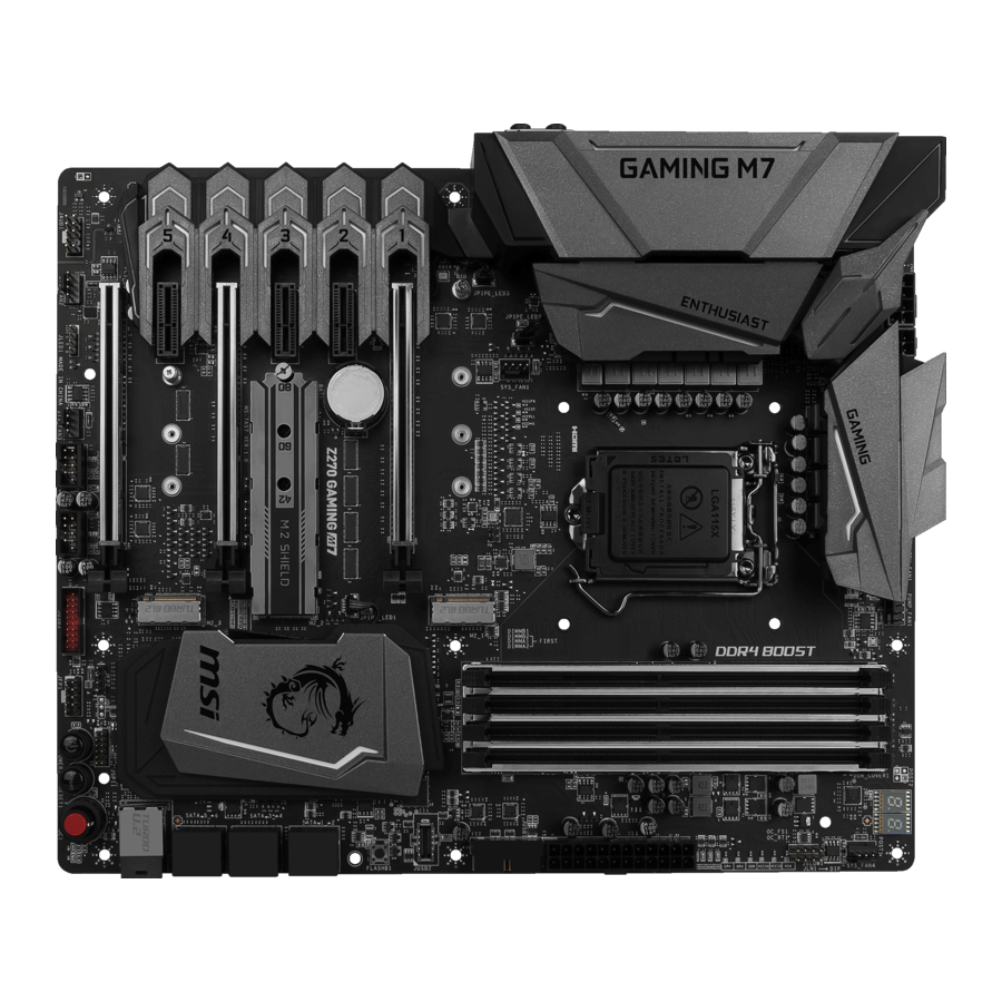
Unpacking
Thank you for buying the MSI
Z270 GAMING M7
motherboard. Check to make sure
®
your motherboard box contains the following items. If something is missing, contact
your dealer as soon as possible.
Drivers & Utilities
Motherboard User
Disc
Guide
Motherboard
I/O Shield
SATA Cable x4
SLI Bridge
M-Connector
Connector
1 to 2 RGB LED Extension
Y Cable 80cm x1
SATA Cable Labels
1
Unpacking
Advertisement
Table of Contents

Related Manuals for MSI Z270 GAMING M7


Summary of Contents for MSI Z270 GAMING M7
-
Page 1: Unpacking
Unpacking Thank you for buying the MSI Z270 GAMING M7 motherboard. Check to make sure ® your motherboard box contains the following items. If something is missing, contact your dealer as soon as possible. Drivers & Utilities Motherboard User Disc... -
Page 2: Safety Information
Safety Information The components included in this package are prone to damage from electrostatic discharge (ESD). Please adhere to the following instructions to ensure successful computer assembly. Ensure that all components are securely connected. Loose connections may cause the computer to not recognize a component or fail to start. Hold the motherboard by the edges to avoid touching sensitive components. -
Page 3: Quick Start
Quick Start Preparing Tools and Components Intel LGA 1151 CPU ® CPU Fan Thermal Paste DDR4 Memory Power Supply Unit Chassis SATA Hard Disk Drive Graphics Card SATA DVD Drive A Package of Screws Phillips Screwdriver Quick Start... -
Page 4: Installing A Processor
Installing a Processor http://youtu.be/bf5La099urI Quick Start... -
Page 5: Installing Ddr4 Memory
Installing DDR4 memory http://youtu.be/T03aDrJPyQs DIMMA2 DIMMA2 DIMMA1 DIMMB2 DIMMB2 DIMMB2 DIMMB1 Quick Start... -
Page 6: Connecting The Front Panel Header
Connecting the Front Panel Header http://youtu.be/DPELIdVNZUI HDD LED + Power LED + HDD LED - Power LED - Reset Switch Power Switch Reset Switch Power Switch JFP1 Reserved No Pin JFP1 HDD LED - HDD LED HDD LED + POWER LED - POWER LED POWER LED + Quick Start... -
Page 7: Installing The Motherboard
Installing the Motherboard Quick Start... -
Page 8: Installing Sata Drives
Installing SATA Drives http://youtu.be/RZsMpqxythc Quick Start... -
Page 9: Installing A Graphics Card
Installing a Graphics Card http://youtu.be/mG0GZpr9w_A Quick Start... -
Page 10: Connecting Peripheral Devices
Connecting Peripheral Devices Quick Start... -
Page 11: Connecting The Power Connectors
Connecting the Power Connectors http://youtu.be/gkDYyR_83I4 ATX_PWR1 CPU_PWR1 CPU_PWR2 Quick Start... -
Page 12: Power On
Power On Quick Start... -
Page 13: Table Of Contents
Contents Unpacking ......................1 Safety Information ....................2 Quick Start ......................3 Preparing Tools and Components ................3 Installing a Processor ..................... 4 Installing DDR4 memory ..................5 Connecting the Front Panel Header ............... 6 Installing the Motherboard ..................7 Installing SATA Drives..................... - Page 14 FLASHB1: BIOS FLASHBACK+ Button ..............41 POWER1, RESET1: Power Button, Reset Button ..........42 JBAT1: Clear CMOS (Reset BIOS) Jumper ............42 OC1: GAME BOOST Knob ..................43 OC_RT1: OC Retry Jumper ................... 44 OC_FS1: OC Force Enter BIOS Jumper ............... 44 JSLOW_1: Slow Mode Booting Jumper ..............
- Page 15 Installing Drivers ....................79 Installing Utilities ....................79 COMMAND CENTER ..................... 80 LIVE UPDATE 6 ...................... 84 MSI SMART TOOL ....................86 GAMING APP ......................89 X-BOOST ....................... 94 RAMDISK....................... 96 Killer Control Center .................... 97 Nahimic 2 ......................98 XSplit Gamecaster V2 ..................
-
Page 16: Specifications
Optane™ Technology is only supported when using 7th Gen processors. ® Before using Intel Optane™ memory modules, please ensure that you have ® updated the drivers and BIOS to the latest version from MSI website. Continued on next page Specifications... - Page 17 Continued from previous page Intel Z270 Chipset ® Supports RAID 0, RAID 1, RAID 5 and RAID 10 for SATA storage devices RAID Supports RAID mode for M.2 PCIe storage devices* * M.2 PCIe RAID volume can be created with M.2 GENIE. Please refer to page 56 for details about M.2 GENIE.
- Page 18 Continued from previous page 1x 24-pin ATX main power connector 1x 8-pin ATX 12V power connector 1x 4-pin ATX 12V power connector 6x SATA 6Gb/s connectors 1x U.2 port 3x M.2 slots 1x USB 3.1 Gen2 Type-C connector 2x USB 3.1 Gen1 connectors (supports additional 4 USB 3.1 Gen1 ports) 2x USB 2.0 connectors (supports additional 4 USB 2.0 ports) 1x 4-pin CPU fan connector...
- Page 19 UEFI AMI BIOS BIOS Features ACPI 5.0, PnP 1.0a, SM BIOS 2.8 Multi-language Drivers SUPER CHARGER FAST BOOT COMMAND CENTER LIVE UPDATE 6 MSI SMART TOOL DRAGON EYE GAMING APP Software X-BOOST RAMDISK Killer Control Center Nahimic Audio XSplit Gamecaster V2...
- Page 20 Lightning X-Boost Military Class 5 7000+ Quality Test VR Boost VR Ready Dragon eye Xsplit RAMDisk GAMING HOTKEY Click BIOS 5 BIOS FLASHBACK+ * This offer is valid for a limited period only, for more information please visit www.msi.com Specifications...
-
Page 21: Block Diagram
Block Diagram HDMI DisplayPort 2 Channel DDR4 Memory PCI Express Bus DMI 3.0 PCIe x1 slot PCIe x1 slot 3 x M.2 PCIe x1 slot 1 x U.2 Switch 6 x SATA 6Gb/s Z270 Killer E2500 6 x USB 3.1 Gen1 PCI Express Bus 7 x USB 2.0 ASMEDIA... -
Page 22: Rear I/O Panel
Rear I/O Panel USB 2.0/ Audio Ports BIOS FLASHBACK+ PS/2 Port USB 3.1 Gen2 DisplayPort Type-A USB 2.0 USB 3.1 Gen2 Type-C Clear CMOS USB 3.1 Gen1 Optical S/PDIF-Out button Clear CMOS button - Power off your computer. Press and hold the Clear CMOS button for 5-10 seconds to reset BIOS to default values. -
Page 23: Realtek Hd Audio Manager
Realtek HD Audio Manager After installing the Realtek HD Audio driver, the Realtek HD Audio Manager icon will appear in the system tray. Double click on the icon to launch. Device Selection Advanced Settings Jack Status Application Enhancement Main Volume Connector Strings Profiles... - Page 24 Audio jacks to headphone and microphone diagram Audio jacks to stereo speakers diagram AUDIO INPUT Audio jacks to 7.1-channel speakers diagram AUDIO INPUT Rear Front Side Center/ Subwoofer Rear I/O Panel...
-
Page 25: Overview Of Components
Overview of Components CPU Socket DIMMB1 DIMMB2 SYS_FAN1 PUMP_FAN1 DIMMA1 CPU_PWR2 CPU_FAN1 DIMMA2 CPU_PWR1 SYS_FAN4 JSLOW1 JLN1 OC_RT1 OC_FS1 ATX_PWR1 JUSB1 JBAT1 M2_1 JUSB2 M2_2 PCI_E1 FLASHB1 M2_3 PCI_E2 SATA▼1▲2 PCI_E3 SATA▼3▲4 JCI1 PCI_E4 SATA▼5▲6 JDISCH1 PCI_E5 U2_1 PCI_E6 JFP2 RESET1 JAUD1 POWER1... - Page 26 Component Contents Port Name Port Type Page CPU_FAN1, PUMP_FAN1, Fan Connectors SYS_FAN1~4 CPU_PWR1~2, ATX_PWR1 Power Connectors CPU Socket LGA1151 CPU Socket DIMMA1, A2, B1, B2 DIMM Slots FLASHB1 BIOS FLASHBACK+ Button JAUD1 Front Audio Connector JBAT1 Clear CMOS (Reset BIOS) Jumper JCI1 Chassis Intrusion Connector JDISCH1...
-
Page 27: Cpu Socket
Always unplug the power cord from the power outlet before installing or removing the CPU. Please retain the CPU protective cap after installing the processor. MSI will deal with Return Merchandise Authorization (RMA) requests if only the motherboard comes with the protective cap on the CPU socket. -
Page 28: Dimm Slots
DIMM Slots DIMMB1 DIMMA1 Channel A Channel B DIMMB2 DIMMA2 Memory module installation recommendation DIMMA2 DIMMA2 DIMMA1 DIMMB2 DIMMB2 DIMMB2 DIMMB1 Important Always insert memory modules in the DIMMB2 slot first. Due to chipset resource usage, the available capacity of memory will be a little less than the amount of installed. -
Page 29: Pci_E1~6: Pcie Expansion Slots
Multiple graphics cards installation recommendation Important If you install a large and heavy graphics card, you need to use a tool such as MSI Gaming Series Graphics Card Bolster to support its weight and to prevent deformation of the slot. - Page 30 Important For a single PCIe x16 expansion card installation with optimum performance, using the PCI_E1 slot is recommended. When adding or removing expansion cards, always turn off the power supply and unplug the power supply power cable from the power outlet. Read the expansion card’...
-
Page 31: U2_1: U.2 Connector
U2_1: U.2 Connector This connector is a U.2 interface port. Each connector can connect to one U.2 NVMe SSD device. Video Demonstration Watch the video to learn how to Install U.2 SSD. http://youtu.be/KgFvKDxymvw Installing U.2 SSD Connect the U.2 cable to the U.2 connector on the motherboard. -
Page 32: M2_1~3: M.2 Slots (Key M)
M2_1~3: M.2 Slots (Key M) Important Intel RST only supports PCIe M.2 SSD with UEFI ROM. ® Intel Optane Memory Ready for all M.2 slots. ® M2_1 Video Demonstration Watch the video to learn how to use M.2 M2_2 Shield. M2_3 https://youtu.be/b-N28ajX_C4 Installing M.2 module... -
Page 33: Sata1~6: Sata 6Gb/S Connectors
SATA1~6: SATA 6Gb/s Connectors These connectors are SATA 6Gb/s interface ports. Each connector can connect to one SATA device. SATA2 SATA1 SATA4 SATA3 SATA6 SATA5 Important Please do not fold the SATA cable at a 90-degree angle. Data loss may result during transmission otherwise. - Page 34 M.2 slots with examples of various combination possibilities 3xM.2 PCIe SSDs + 4xSATA HDDs 2xM.2 PCIe SSDs + 1x U.2 SSD + 4xSATA HDDs PCIe PCIe PCIe PCIe PCIe U2_1 2xM.2 PCIe SSDs + 6xSATA HDDs 2xM.2 SATA SSDs + 1xM.2 PCIe SSD+ 3xSATA HDDs PCIe SATA...
-
Page 35: Cpu_Pwr1~2, Atx_Pwr1: Power Connectors
CPU_PWR1~2, ATX_PWR1: Power Connectors These connectors allow you to connect an ATX power supply. CPU_PWR1 Ground +12V Ground +12V Ground +12V Ground +12V CPU_PWR2 Ground +12V Ground +12V +3.3V +3.3V +3.3V -12V Ground Ground PS-ON# Ground Ground Ground ATX_PWR1 Ground Ground PWR OK 5VSB... -
Page 36: Jusb4~5: Usb 2.0 Connectors
JUSB4~5: USB 2.0 Connectors These connectors allow you to connect USB 2.0 ports on the front panel. USB0- USB1- USB0+ USB1+ Ground Ground No Pin Important Note that the VCC and Ground pins must be connected correctly to avoid possible damage. -
Page 37: Jusb2: Usb 3.1 Gen2 Type-C Connector
However, when you boot the computer into Windows ® you will need to install the MSI SUPER CHARGER application to turn ON/OFF the ®... -
Page 38: Jfp1, Jfp2: Front Panel Connectors
JFP1, JFP2: Front Panel Connectors These connectors connect to the switches and LEDs on the front panel. JFP1 HDD LED + Power LED + HDD LED - Power LED - Reset Switch Power Switch Reset Switch Power Switch Reserved No Pin Speaker - Buzzer + JFP2... -
Page 39: Cpu_Fan1, Pump_Fan1, Sys_Fan1~4: Fan Connectors
CPU_FAN1, PUMP_FAN1, SYS_FAN1~4: Fan Connectors Fan connectors can be classified as PWM (Pulse Width Modulation) Mode or DC Mode. PWM Mode fan connectors provide constant 12V output and adjust fan speed with speed control signal. DC Mode fan connectors control fan speed by changing voltage. When you plug a 3-pin (Non-PWM) fan to a fan connector in PWM mode, the fan speed will always maintain at 100%, which might create a lot of noise. -
Page 40: Jci1: Chassis Intrusion Connector
JCI1: Chassis Intrusion Connector This connector allows you to connect the chassis intrusion switch cable. Normal Trigger the chassis intrusion event (default) Using chassis intrusion detector Connect the JCI1 connector to the chassis intrusion switch/ sensor on the chassis. Close the chassis cover. Go to BIOS >... -
Page 41: Jled1: Rgb Led Connector
JLED1: RGB LED connector This connector allows you to connect the 5050 RGB LED strips. +12V 5050 LED strip Extension cable JLED1 Video Demonstration Watch the video to learn how to install 5050 RGB LED strips to RGB LED connector. https://youtu.be/CqNHyADzd2Q Important This connector supports 5050 RGB multi-color LED strips (12V/G/R/B) with the... -
Page 42: Power1, Reset1: Power Button, Reset Button
POWER1, RESET1: Power Button, Reset Button The Power / Reset button allows you to power on / reset the computer. POWER1 RESET1 (Power button) (Reset button) JBAT1: Clear CMOS (Reset BIOS) Jumper There is CMOS memory onboard that is external powered from a battery located on the motherboard to save system configuration data. -
Page 43: Oc1: Game Boost Knob
OC1: GAME BOOST Knob This knob allows you to manually select a stage from number 0 (default) to number 11 (extreme) for overclocking the Intel K-SKU processors. The processor’ s voltage and frequency will be automatically adjusted after you power on your computer. Instant OC button GAME BOOST knob Using GAME BOOST Knob... -
Page 44: Oc_Rt1: Oc Retry Jumper
Rotate the GAME BOOST knob to 0 and then power on. The configuration parameters will be returned to its default values. Important You can also control the GAME BOOST function in BIOS Setup or with MSI COMMAND CENTER software. In order to optimize performance and improve system stability, when you activate the GAME BOOST function, please leave the settings in the BIOS >... -
Page 45: Jslow_1: Slow Mode Booting Jumper
JSLOW_1: Slow Mode Booting Jumper This jumper is used for LN2 cooling solution, that provides the extreme overclocking conditions, to boot at a stable processor frequency and to prevent the system from crashing. You can connect a button to this jumper, and press the button to enable the Slow Mode. -
Page 46: Onboard Leds
Onboard LEDs EZ Debug LEDs These LEDs indicate the status of key components during booting process. When an error is occurred, the corresponding LED stays lit until the problem is solved. CPU - indicates CPU is not detected or fail. DRAM - indicates DRAM is not detected or fail. -
Page 47: Fan Leds
Fan LEDs These LEDs indicate the fan control mode. PUMP_FAN1 LED LED Color Fan control mode CPU_FAN1 LED PWM mode Green DC mode BIOS FLASHBACK+ LED BIOS FLASHBACK+ LED indicates BIOS flash is in progress. BIOS FLASHBACK+ LED GAME BOOST LEDs These LEDs indicate GAME BOOST control status. -
Page 48: Pcie X16 Slot Leds
PCIe x16 slot LEDs These LED indicate the PCIe x16 slots status. LED Color PCIe slot speed status White x8, x4, x1 PCI_E1 LED PCI_E4 LED PCI_E6 LED Debug Code LED The Debug Code LED displays progress and error codes during and after POST. Refer to the Debug Code LED table for details. -
Page 49: Debug Code Led Table
Debug Code LED Table SEC Progress Codes CPU post-memory initialization. Cache initialization Power on. Reset type detection (soft/ CPU post-memory initialization. hard) Application Processor(s) (AP) initialization AP initialization before microcode loading CPU post-memory initialization. Boot System Agent initialization before Strap Processor (BSP) selection microcode loading CPU post-memory initialization. - Page 50 CPU DXE initialization is started Start of Setup CPU DXE initialization (CPU module Setup Input Wait 64 - 67 specific) Ready To Boot event PCI host bridge initialization Legacy Boot event System Agent DXE initialization is started Exit Boot Services event System Agent DXE SMM initialization is Runtime Set Virtual Address MAP Begin started...
-
Page 51: Acpi States Codes
S3 Resume Error Codes System has transitioned into ACPI mode. Interrupt controller is in APIC mode. S3 Resume Failed CPU Temperature S3 Resume PPI not Found S3 Resume Boot Script Error Displays current CPU temperature after 00 - 99 S3 OS Wake Error the system has fully booted into the OS. -
Page 52: Bios Setup
Press Delete key, when the Press DEL key to enter Setup Menu, F11 to enter Boot Menu message appears on the screen during the boot process. Use MSI FAST BOOT application. Click on GO2BIOS button and choose OK. The system will reboot and enter BIOS setup directly. -
Page 53: Resetting Bios
Updating BIOS Updating BIOS with M-FLASH Before updating: Please download the latest BIOS file that matches your motherboard model from MSI website. And then save the BIOS file into the USB flash drive. Updating BIOS: Press Del key to enter the BIOS Setup during POST. - Page 54 Before updating: Please download the latest BIOS file that matches your motherboard model from MSI ® website and rename the BIOS file to MSI.ROM. And then, save the MSI.ROM file to the root of USB flash drive. Important Only the FAT32 format USB flash drive supports updating BIOS by BIOS FLASHBACK+.
-
Page 55: Ez Mode
EZ Mode At EZ mode, it provides the basic system information and allows you to configure the basic setting. To configure the advanced BIOS settings, please enter the Advanced Mode by pressing the Setup Mode switch or F7 function key. Screenshot Setup Mode switch XMP switch... - Page 56 RAID 0 volume. During windows setup, the RAID driver may be required and you can find the RAID driver in MSI Driver Disc. You can use MSI SMART TOOL to build the Windows 7/ 8.1/ 10 installation drive ®...
-
Page 57: Advanced Mode
Advanced Mode Press Setup Mode switch or F7 function key can switch between EZ Mode and Advanced Mode in BIOS setup. Screenshot XMP switch Setup Mode switch Search Language System information GAME BOOST switch Boot device priority bar BIOS menu BIOS menu selection selection... -
Page 58: Settings
SETTINGS System Status System Date Sets the system date. Use tab key to switch between date elements. The format is <day> <month> <date> <year>. <day> Day of the week, from Sun to Sat, determined by BIOS. Read-only. <month> The month from Jan. through Dec. <date>... - Page 59 fPEG X - Max Link Speed [Auto] Sets PCI Express protocol of PCIe x16 slots for matching different installed devices. [Auto] This item will be configured automatically by BIOS. [Gen1] Enables PCIe Gen1 support only. [Gen2] Enables PCIe Gen2 support only. [Gen3] Enables PCIe Gen3 support only.
- Page 60 fIpv6 PXE Support [Enabled] When Enabled, the system UEFI network stack will support Ipv6 protocol. This item will appear when Network Stack is enabled. [Enabled] Enables the Ipv6 PXE boot support. [Disabled] Disables the Ipv6 PXE boot support. fSATA Mode [AHCI Mode] Sets the operation mode of the onboard SATA controller.
- Page 61 fIGD Multi-Monitor [Disabled] Enables or disables the multi-screen output from integrated graphics and external graphics card. This item appears when Initiate Graphic Adapter set to PEG. [Enabled] Enables multi-screen function for both integrated and external graphics cards. [Disabled] Disables this function. USB Configuration Sets the onboard USB controller and device function.
- Page 62 Disables this function. fMSI Fast Boot [Disabled] MSI Fast Boot is the fastest way to boot the system. It will disable more devices to speed up system boot time which is faster than the boot time of Fast Boot. [Enabled] Enables the MSI Fast Boot function to speed up booting time.
- Page 63 fKey Management Manages the secure boot keys. Press <Enter> to enter the sub-menu. This sub- menu will appear when Secure Boot Mode sets to Custom. Wake Up Event Setup Sets system wake up behaviors for different sleep modes. Press Enter to enter the sub-menu.
-
Page 64: Boot
fHot Key [Ctrl+Space] Selects a combination of keys as a hot key to wake the system. This item appears when you set the Resume From S3/S4/S5 by PS/2 Keyboard to Hot Key. Secure Erase+ Enables or disables Secure Erase+ function. Secure Erase+ is the best way to effectively wipe all data from a SSD. -
Page 65: Security
Security Administrator Password Sets administrator password for system security. User has full rights to change the BIOS items with administrator password. After setting the administrator password, the state of this item will show “Installed” . User Password Sets User Password for system security. User has limited rights to change the BIOS items with user password. -
Page 66: Save & Exit
fChassis Intrusion [Disabled] Enables or disables recording messages when the chassis is opened. This function is ready for the chassis equips a chassis intrusion switch. [Enabled] Once the chassis is opened, the system will record and issue a warning message. [Reset] Clear the warning message. - Page 67 Important Overclocking your PC manually is only recommended for advanced users. Overclocking is not guaranteed, and if done improperly, it could void your warranty or severely damage your hardware. If you are unfamiliar with overclocking, we advise you to use GAME BOOST function for easy overclocking.
- Page 68 GT Ratio [Auto] Sets the integrated graphics ratio. The valid value range depends on the installed CPU. Adjusted GT Frequency Shows the adjusted integrated graphics frequency. Read-only. Misc Setting* Press Enter, + or - key to open or close the following 3 items related to CPU features. fEIST [Enabled]* Enables or disables the Enhanced Intel SpeedStep Technology.
- Page 69 fThreshold 1~3 (A) [Auto] Sets the CPU current as the threshold for Dynamic Frequency Control. When CPU current reaches the value, it will run the Level 1/ 2/ 3 BCLK for dynamic overclocking. These items will appear when the Dynamic Frequency Control is enabled.
- Page 70 Memory Try It ! [Disabled] It improve memory compatibility or performance by choosing optimized memory preset. Advanced DRAM Configuration Press Enter to enter the sub-menu. User can set the memory timing for each/ all memory channel. The system may become un-stable or un-bootable after changing memory timing.
- Page 71 fCPU VRM Over Temperature Protection [Enabled] Sets the temperature limit on CPU VRM for over-temperature protection. The CPU frequency may be throttled when CPU temperature over the specified temperature. If set to Auto, BIOS will configure this settings. fCPU GT Loadline Calibration Control [Auto] The voltage of the GPU embeeded in CPU will decrease proportionally according to GPU loading.
- Page 72 fDRAM Over Current Protection [Auto] Sets the current limit for DRAM over-current protection. If set to Auto, BIOS will configure this setting automatically. [Auto] This setting will be configured automatically by BIOS. [Enhanced] Extends the current range for over-current protection. fDRAM Switching Frequency [Auto] Sets the PWM working speed to stabilize DRAM voltage and minimize ripple range.
- Page 73 MEMORY-Z Press Enter to enter the sub-menu. This sub-menu displays all the settings and timings of installed memory. You can also access this information menu at any time by pressing [F5]. fDIMMA1/ A2/ B1/ B2 Memory SPD Press Enter to enter the sub-menu. The sub-menu displays the information of installed memory.
- Page 74 fAdjacent Cache Line Prefetch [Enabled] Enables or disables the CPU hardware prefetcher (MLC Spatial prefetcher). [Enabled] Enables adjacent cache line prefetching for reducing the cache latency time and tuning the performance to the specific application. [Disabled] Enables the requested cache line only. fCPU AES Instructions [Enabled] Enables or disables the CPU AES (Advanced Encryption Standard-New Instructions) support.
- Page 75 fEIST [Enabled] Enables or disables the Enhanced Intel SpeedStep Technology. This item will ® appear when OC Explore Mode is set to Normal. [Enabled] Enables the EIST to adjust CPU voltage and core frequency dynamically. It can decrease average power consumption and average heat production.
-
Page 76: M-Flash
M-FLASH provides the way to update BIOS with a USB flash drive. Please down-load the latest BIOS file that matches your motherboard model from MSI website, save the BIOS file into your USB flash drive. And then follow the steps below to update BIOS. -
Page 77: Oc Profile
OC PROFILE Overclocking Profile 1/ 2/ 3/ 4/ 5/ 6 Overclocking Profile 1/ 2/ 3/ 4/ 5/ 6 management. Press <Enter> to enter the sub- menu. fSet Name for Overclocking Profile 1/ 2/ 3/ 4/ 5/ 6 Name the current overclocking profile. fSave Overclocking Profile 1/ 2/ 3/ 4/ 5/ 6 Save the current overclocking profile. -
Page 78: Hardware Monitor
HARDWARE MONITOR Temperature & Speed Fan Manage Setting Buttons Voltage display Temperature & Speed Shows the current CPU temperature, system temperature and fans' speeds. Fan Manage PWM - allows you to select the PWM mode for fan operation. ƒ DC - allows you to select the DC mode for fan operation. ƒ... -
Page 79: Software Description
Note: Due to chipset limitation, during the Windows 7 installation process, USB ® optical drives or USB flash drives are not supported. You can use MSI Smart Tool to install Windows ® Press the Restart button on the computer case. -
Page 80: Command Center
COMMAND CENTER COMMAND CENTER is an user-friendly software and exclusively developed by MSI, helping users to adjust system settings and monitor status under OS. With the help of COMMAND CENTER, making it possible to achieve easier and efficient monitoring process and adjustments than that under BIOS. In addition, the COMMAND CENTER can be a server for mobile remote control application. - Page 81 CPU Fan CPU Fan control panel provides Smart mode and Manual Mode. You can switch the control mode by clicking the Smart Mode and Manual Mode buttons on the top of the CPU Fan control panel. Manual Mode - allows you to manually control the CPU fan speed by percentage.
- Page 82 GAME BOOST GAME BOOST has 8 overclocking stages for you to overclock your computer. COMMAND CENTER provides the software interface instead of GAME BOOST knob on the motherboard. You can click on the center button to switch GAME BOOST control between software (SW) and hardware (HW) .
- Page 83 Find the IP address on the SoftAP Management Setting area, and enter the IP address on your MSI COMMAND CENTER APP to link your system. ® Press Refresh on the MSI COMMAND CENTER APP to verify that monitoring and ® OC functions are working properly.
-
Page 84: Live Update 6
® drivers, BIOS and utilities. With LIVE UPDATE 6, you do not need to search the drivers on specific MSI web page. LIVE UPDATE 6 will download the appropriate drivers automatically. Download Options... -
Page 85: Total Installer
Choose Automatic scan, system will automatically scan all the items and search for the latest update files. Or you can choose Manual scan and select the items you wish to scan. Click the Scan button at the bottom. It may take several minutes to complete the process. -
Page 86: Msi Smart Tool
MSI SMART TOOL MSI SMART TOOL is a convenient tool that can help you to create your Windows installation USB flash drive with USB 3.0 drivers, and it can also create a software RAID. Main menu After installing and activating MSI SMART TOOL, it will display a main menu for you to choose Win7 Smart Tool or Software RAID. - Page 87 SOFTWARE RAID This utility allows you to create a software RAID in Windows system. To create a software RAID: Use checkboxs to select the disks you want included in your RAID. Choose Speed Up or Backup for RAID type. y Speed Up = RAID0 y Backup = RAID1 Click Start.
- Page 88 DRAGON EYE DRAGON EYE allows you to watch game guides, tutorials, live match or tournament stream while gaming. In game, you can use hotkeys to control/adjust the settings of DRAGON EYE. Size Settings Position Settings On / Off Switch Help Transparency Settings Video List Hotkeys Information...
-
Page 89: Gaming App
Connect your android device and motherboard to the same local area network. Run MSI GAMING APP APP on your android device. ® Press the Remote Control Setting icon on the MSI GAMING APP APP to find the ® paired device Name you set in the Remote Control Setting panel. - Page 90 LED function allows you to control LED lights on your motherboard. ON/OFF LED Area Selection LED ON/OFF - allows you to turn ON/ OFF the LED function. LED Area Selection - separately controls each segment of LEDs on your motherboard, graphics cards and extend LED strip. LED effects - switches LEDs on or off.
- Page 91 Eye Rest Eye Rest allows you to optimize the display on your monitor. EyeRest - reduces blue-light of your LED backlit screen, in order to protect your eyes. Gaming - automatically increase contrast ratio of your screen. Movie - automatically increase dynamic contrast ratio of your screen. Customize - allows you to adjust gamma, contrast and color balance for your screen.
- Page 92 Login Keys - provides hotkey login function. ƒ MSI Smart Keys - allows you to define hotkeys for MSI Smart Keys. ƒ Hotkey Manager - allows you to create, edit and delete hotkeys. Current Hotkeys - shows all existing hotkeys.
- Page 93 Mouse Master Mouse Master provides mouse macro function. You can also use it to change DPI of your mouse. DPI Setting Delay Time Default Button Macro Hot Key DPI Hot Key Mouse Action Action List Test Area Edit Buttons Clear Button Load Button Save Button Delay Time - allows you to apply a delay time in mouse macro.
-
Page 94: X-Boost
X-BOOST The MSI X-BOOST allows you to select the system performance mode to meet your current system environment or support faster storage access speed for your external storage or memory cards. Easy In Easy page, you can select one system performance mode to meet the current system environment. - Page 95 Setting - enables or disables Run X-BOOST when windows starts. Important Please note that you can only select one mode at a time from Easy or Advance page as MSI X-BOOST function. The improved transfer rate/ access speed will vary with the USB/ storage device. Software Description...
-
Page 96: Ramdisk
RAMDISK RAMDISK creates a virtual RAM drive using the available memory in your computer, the performance of the RAMDISK is faster than an SSD and hard drive. RAMDISK allows you to store any temporary information on it. Furthermore, using the RAMDISK will extend your SSD’... -
Page 97: Killer Control Center
Killer Control Center The killer Control Center software can be installed with the Killer LAN driver. Once installed, the Killer Control Center icon would appear in system tray (bottom right of the screen). Right click on the icon to open application window. In case no icon appears in system tray, you may activate Killer Control Center manually by double clicking the Killer Control Center icon on the desktop. -
Page 98: Nahimic 2
HD Audio Recorder2 and Sound Tracker. Installation and Update Nahimic 2 is included in the audio driver. If you need to install it or update it, please use the Driver Disc with your motherboard or download the driver from MSI’ s official website. Audio Tab From this tab, you can access all of Nahimic 2’... - Page 99 Smart Loudness - maintains a constant volume for all elements of the audio ƒ experience to making them all sound softer, balanced or louder. Voice Clarity - boosts the speech in movies, video games and incoming ƒ communication from +0 through +12 dB (0 to 100%). Reset Button - restores the current profile to its default values.
- Page 100 Device properties - allows you to boost the volume and modify the left/ right ƒ balance of microphone. Clicks on this button and a device properties panel will show. Microphone Loopback - turns the microphone loopback On/Off. In order to avoid any feedback (Larsen effect).
- Page 101 Control Page - by clicking the arrow button, you can access the control page. Audio Launchpad ON/OFF - switches the Audio Launchpad on or off. ƒ HD Audio Recorder 2 - The HD Audio Recorder 2 is, by default, automatically ƒ...
-
Page 102: Xsplit Gamecaster V2
Login button. Important When starting XSplit Gamecaster V2 on select MSI gaming laptops, all-in ones or on ® machines that contain select MSI motherboards or graphics cards, you will receive ®... - Page 103 Learning stream and record Refer to the Start page of XSplit Gamecaster V2 to learn how to stream and record your gameplay. Tool Tip When you click the question mark next to a feature name on the panel, a tooltip will show, describing the particular function of that item.
- Page 104 Share Button - If you authorize your Facebook, Twitter, and/or Google+ accounts, you can quickly share your stream URL and status update within the overlay. Annotations - This feature of XSplit Gamecaster V2 allows you to draw directly onto your game play. You can activate annotation mode by clicking on the pencil button in the overlay.
- Page 105 Microphone Settings - In this region, you can select your desired microphone. What is shown in the list depends on what you have connected to your PC. If you don’ t see your desired device in the list, please make sure that it is detected and it is not disabled in your recording devices list in the Windows Sound Menu (Start >...
-
Page 106: Steelseries Engine 3
SteelSeries Engine 3 SteelSeries Engine 3 is a unified platform built to support all of SteelSeries products. It can deploy your saved device settings automatically when switching between your favorite games or applications. After installation the SteelSeries Engine background processes will start and the interface will open automatically. - Page 107 Configuring Your Devices You can custom configurations for SteelSeries devices in their Configuration Windows. The top left displays the name of the configuration you are viewing, the body features widgets for customizing various functions of the device, and at the bottom are Save/ Revert buttons, a Live Preview toggle, and a button to open/close the collapsible Configuration List Panel.
-
Page 108: Intel ® Extreme Tuning Utility
Intel Extreme Tuning Utility ® Intel Extreme Tuning Utility (Intel XTU) is a simple overclocking software for you to ® tune, test and monitor your system. Tuning Controls Views Settings Help System Navigation Table System System Monitors Graphs Views Settings Help Views - toggles to switche between Monitoring and Show All view. -
Page 109: Cpu-Z
CPU-Z CPU-Z is an utility that gathers information on some of the main devices of your system. CPU Tab - shows processor name, code name, package, specification, instructions sets, core speed and cache levels. Caches Tab - shows extended information related to the cache capabilities. Mainboard Tab - shows motherboard manufacturer, model name, chipset, BIOS version and graphic interface. -
Page 110: Raid Configuration
RAID Configuration Below are the different types of a RAID. RAID 0 breaks the data into blocks which are written to separate hard drives. Spreading the hard drive I/O load across independent channels greatly improves I/O performance. RAID 1 provides data redundancy by mirroring data between the hard drives and provides enhanced read performance. - Page 111 Creating s RAID Volume Select option Create RAID Volume and press Enter key. The following screen appears. CREATE VOLUME MENU Name : Volume0 RAID Level : RAID1(Mirror) Disks : Select Disks Strip Size : N / A Capacity : XXX.X GB Sync : N / A Create Volume...
- Page 112 Removing a RAID Volume Here you can delete the RAID volume, but please be noted that all data on RAID drives will be lost. Important If your system currently boots to RAID and you delete the RAID volume in the IRST Option ROM, your system will become unbootable.
-
Page 113: Degraded Raid Array
Important You will lose all data on the RAID drives and any internal RAID structures when you perform this operation. Possible reasons to Reset Disks to Non-RAID could include issues such as incompatible RAID configurations or a failed volume or failed disk. Recovery Volume Options Select option Recovery Volume Options from the main menu screen and press Enter to change recovery volume mode. -
Page 114: Failed Hard Drive Member
Reboot to Windows ; the rebuild will occur automatically. ® Failed Hard Drive Member Power off. Replace the failed hard drive with a new one that is of equal or greater capacity. Reboot the system to IRST Option ROM by press Ctrl + I keys during the POST. Select the port of the destination disk for rebuilding, and then press Enter. -
Page 115: M.2 Pcie Ssd Raid
M.2 PCIe SSD RAID You can create M.2 PCIe SSD RAID volume with UEFI BIOS. Creating a M.2 PCIe SSD RAID Volume Access the BIOS setup Switch to Advanced Mode by pressing F7 key. Go to SETTINGS > Advanced > Windows OS Configuration. Set Windows 8.1/10 WHQL Support to Enabled. - Page 116 Removing a M.2 PCIe SSD RAID Volume Here you can delete the M.2 PCIe SSD RAID volume, but please be noted that all data on M.2 PCIe SSDs will be lost. Important If your system currently boots to M.2 PCIe SSD RAID and you delete the RAID volume in the UEFI BIOS, your system will become unbootable.
-
Page 117: Troubleshooting
Troubleshooting Lost BIOS password Before sending the motherboard for RMA repair, try to go over troubleshooting Clear the CMOS, but that will cause guide first to see if your got similar you to lose all customized settings in symptoms as mentioned below. the BIOS. -
Page 118: Regulatory Notices
EU REACH Regulation (Regulation EC No. 1907/2006 of the European Parliament and the This device complies with part 15 of the FCC Rules. Council), MSI provides the information of chemical Operation is subject to the following two conditions: substances in products at: (1) This device may not cause harmful interference, and http://www.msi.com/html/popup/csr/evmtprtt_pcm. - Page 119 MSI will comply with the product take entregar a una empresa autorizada para la recogida de back requirements at the end of life of MSI-branded estos residuos.
- Page 120 MSI si adeguerà a tale Direttiva ritirando tutti i prodotti marchiati MSI che sono stati venduti all’interno dell’Unione Europea alla fine del loro ciclo di vita.
- Page 121 Alternatively, please try the following help resources for further guidance. y Visit the MSI website for technical guide, BIOS updates, driver updates, and other information: http://www.msi.com y Register your product at: http://register.msi.com...
Need help?
Do you have a question about the Z270 GAMING M7 and is the answer not in the manual?
Questions and answers