Table of Contents
Advertisement
Advertisement
Table of Contents

Related Manuals for Sebury BC-2000


Summary of Contents for Sebury BC-2000
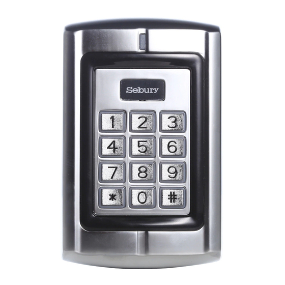
- Page 1 BC-2000 Digital Keypad...
-
Page 2: Table Of Contents
CONTENTS Page Introduction ……………………………………… Product Specifications ………………….…….… Intramural Interface Circuit ……………………… Mounting & PCB Diagram ………………………. Wiring Diagram …………………………………… 7 Engineer Programming Information and Notes… 9 Changing Master & User Codes…………… Adding User Codes & Cards………. ……… 10 Delete User Card or Cards…………..……… 10 User Operation Mode…………………………... -
Page 3: Introduction
Codes and operating parameters are stored within the microprocessor and can not be lost due to power failure. The BC-2000 can store 1000 prox cards and user 4 digit codes. Each 4 digit code has 10,000 possible combinations. The unit has one relay with 5 Amp... -
Page 4: Product Specifications
Specifications Programmable Functions Relay latching or momentary Relay activate independently or together Change Codes 1 master, 1000 users & prox cards Door open detection Programmable Timers Door relay time 00-99 seconds Door open detection 00-99 seconds Alarm time 00-99 minutes Wiring Connections Electric lock External bell... -
Page 5: Intramural Interface Circuit
NOTE PLEASE READ THESE INSTRUCTIONS CAREFULLY BEFORE ATTEMPTING TO INSTALL THE BC-2000 Intramural Interface Circuit Alarm output interface (See Figure 1) Electric lock interface (See Figure 2) Figure 1 Figure 2... -
Page 6: Mounting & Pcb Diagram
When wiring has been completed, attach the front cover to the rear plate. Figure 3 Figure 4 The front cover can be permanently secured by using the short screw supplied BC-2000 Printed Circuit Board... -
Page 7: Wiring Diagram
Wiring Unplug the cable harness and connect the necessary cables, (See Figure 5). Tape any wires that are unused. Plug the cable harness , (See Figure 5) Attach the front cover, (See Figure 3). Terminal Wire Connector 1 Function 10 Bell1 White Bell Push Button Bell2... - Page 8 Figure 5...
-
Page 9: Engineer Programming Information And Notes
Power Up After all wiring is complete and the unit face plate is attached to the back plate, apply 12Vdc power to the unit. Accept LED(the yellow LED) flashing. Engineer Programming Mode To enter programming mode Press: within 5 seconds, Ready(the green * 9999 # LED) and Accept LED illuminated, Open LED flashing. -
Page 10: Adding User Codes & Cards
# key. 1 card must be 000 up to 999. Then the BC-2000 control station added a user card it was auto added a user code with 1234. Delete User Card or Cards There are 3 options to delete a user card or cards, in engineering mode. -
Page 11: Setting Door Relay Strike
Press: valid card only Press: valid card and password Press: valid card or password Setting Door Relay Strike Time The door relay output can be operated as either normally opened or normally closed, a maximum current of 10 ampere can pass through the relay if used as normally opened or 5 ampere if normally closed. -
Page 12: Setting Security Arrangement
a.) If door not closed after opening, keypad buzzer sounds. b.) If door forced open, keypad buzzer sounds and sends alarm signal. Setting Security Arrangement There are two levels of keypad security available for the BC- 2000. Press: to read 10 invalid cards or valid cards, then enter 4 wrong passwords in succession, the keypad is locked for 10 minutes. -
Page 13: Changing User Password Code
Reset Non Volatile Memory by switching of the power and placing the jumper connector onto the pins 1 & 2 as per figure 2. After switching power on remove jumper, the BC- 2000 will give a beep and is now reset to factory default values. -
Page 14: Technical Specifications
Technical Specification DC Supply Voltage: Low voltage input 12 ±10% Vdc unregulated Current Consumption: 100mA @ quiescent maximum Door Relay: 5Amp 12Vdc Alarm output load: 150mA pull current Tamper Protection: Negative loop, normally closed Codes : 1 Master, 1000 cards and 1000 codes . -
Page 15: Package Listing
Package Listing Name Model no. Quantity Remark Digital Keypad BC-2000 User Manual BC-2000 Used for front Flat Head Φ3mm×6mm case and back Screws case Φ6mm×27 mm Pastern Stopper Used for fixing Self Tapping Φ3.5mm×27 mm Used for fixing Screws...
Need help?
Do you have a question about the BC-2000 and is the answer not in the manual?
Questions and answers