Advertisement
Quick Links
To add and delete users in card and PIN mode ( 3 1 # )
To Add a card and Pin user
(The PIN is any four digits between
0000 ~ 9999 with the exception of
1234 which is reserved.)
To change a PIN in card and PIN
mode (Method 1) Note that this is
done outside programming mode
so the user can undertake this
themselves
To change a PIN in card and PIN
mode (Method 2) Note that this is
done outside programming mode
so the user can undertake this
themselves
W1/W3-B Quick Reference Programming Guide
To delete a Card and PIN user just
*
Master code
#
delete the card
To enter the programming mode
888888 is the default factory master code
To exit from the programming mode
*
To add a card user in card only mode ( 3
No te that to un dertake the followi ng pr ogrammi ng the ma ster us er mus t be logged in
To Add and Delete a card user
To change the master code
The master code is any 6 digits
To delete All users
1
User ID number
#
PIN
#
The ID number is any number between 1 ~ 2500.
To delete ALL users. Note that
this is a dangerous option so use
The PIN is any four digits between 0000 ~ 9999
To add a PIN user
with the exception of 1234 which is reserved.
with care
Users can be added continuously without exiting
programming mode
1
Read Card
#
To add and delete card users by Manager cards
To add a card user
Cards can be added continuously without
exiting from programming mode
To add card user by Manager Add Card
To delete a PIN or a card user
Users can be deleted continuously without
To delete card User by Manager
exiting from programming mode
Delete Card
To Unlock the door
Present the card
To unlock the door
For a PIN user
Enter the PIN then press #
Add the card as for a card user
Press * to exit from the programming mode
For a card user
Read card
Then allocate the card a PIN as follows:
*
Read Card
1234 # PIN # PIN #
For a card and PIN user
Read card then enter PIN #
10.2 Door Relay, Door Open Detection, Alarm, Facility code Settings
* Read Card Old PIN # New PIN # New PIN #
Door relay time setting
4 0~99 #
Door relay time setting
The door relay time is between 0~99 seconds,
the factory default setting is 5 seconds.
* ID number# Old PIN # New PIN # New PIN #
Door Open Detection
Door Open Too Long (DOTL) warning. When used with an optional magnetic contact
or built-in magnetic contact of the lock, if the door is opened normally, but not closed
2 User ID #
after 1 minute, the inside buzzer will beep automatically to remind people to close
the door and continue for 1 minute before switching off automatically.
Door Forced Open warning. When used with an optional magnetic contact or built-in
0 # )
magnetic contact of the lock, if the door is forced open, or if the door is opened after
20 seconds of the electro-mechanical lock not closed properly, the inside buzzer
The operating is the same as adding and deleting
and alarm output will both operate. The Alarm Output time is adjustable between 0-3
a card user in 3 2 #
minutes with the default being 1 minute.
To disable door open detection.
6 0 #
(Factory default setting)
2 0000 #
6
2
#
To enable door open detection
Alarm output time
To set the alarm output time (0~3
9 0~3 #
Manager add card Read card Manager add card
minutes) Factory default is 1 minute
Cards can be added continuously.
Keypad Lockout & Alarm Output options. If there are 10 invalid cards or 10
incorrect PIN numbers in a 10 minute period either the keypad will lockout for 10
Manager delete card Read Card Manager delete card
Cards can be deleted continuously.
minutes or the alarm will operate for 10 minutes, depending on the option selected
below.
Normal status: No keypad lockout
7 0 # (Factory default setting)
or alarm
.7.
.8.
7 1 #
Transmission Format:
Keypad Lockout
◆ 1: Keypad Transmission
7 2 #
Alarm Output
The Reader will transmit the PIN data when it receives the last key (#) press after
To remove the alarm
PIN code.
Format: Facility Code + PIN Code
To reset the Door Forced Open warning
Read valid card or Master Code #
(Facility code is any digits between 0~255, factory default is 0; Pin code is any 1~4
digits between 0~9999)
To reset the Door Open Too Long warning
Close the door or Read vali d card or Master Code #
Example: Facility code: 1
PIN code: 5678
Press 5678 #, then the output format will be: 00105678
To se t the facility co de
◆ 2: Proximity Card Transmission
To set the facility code of W1/W3-
The Reader will transmit the card data when it reads the Card.
8 Facility code # Repeat Facility code #
B
Facility Code can be any number between
(This operation might be required
Format: Card Number (the last 8 digits of Card Number)
1~255 (Default: 0)
w h e n W 1 / W 3 - B i s a c t i n g a s
wiegand reader and connecting to
Remarks: No matter the card or pin is valid or invalid, the data will be transmitted
11.2 W1/W3-B operating as a Controller
11 Interconnecting Two Devices
In this mode the W1/W3-B supports a Wiegand 26 bit input so an external Wiegand
device with a 26 bit output can be connected to the Wiegand input terminals on the
11.1 W1/W3-B operating as a Wiegand Output Reader
W1/W3-B. Either an ID card reader (125KHZ) or an IC card reader (13.56MHZ) can
be connected to the W1/W3-B. Cards are required to be added at the external reader,
In this mode the W1/W3-B supports a Wiegand 26 bit output so the Wiegand data lines
except where an external EM reader is used, in this case cards can be added at either
can be connected to any controller which supports a Wiegand 26 bit input. See figure 1.
reader or controller. See figure 2.
Pink
GND
Pink
GND
Green
D0
D0
Green
D0
White
D1
D1
White
D1
GND
Grey
ALARM-
Grey
ALARM-
Yellow
OPEN
Yellow
V+
OPEN
Brown
D_IN
Brown
D_IN
Red
AC&DC
Red
AC&DC
Black
Black
AC&DC
AC&DC
V+
Blue
NO
Blue
NO
GND
Purple
COM
Purple
COM
Power
NC
Orange
Orange
Controller
NC
(With Wiegand 26 inPut)
W1/W3-B
W1/W3-B
.9.
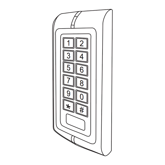
Waterproof
Keypad/Reader/Controller
1
2
Special Power Supply
3
4
1 2 V
DC
/3A
5
6
Wiegand reader
NC
COM NO +12V GND
OPEN
7
8
D0
9
D1
0
+
-
-
Exit button
+
Fail-Secure lock
Fail-Secure lock
GND
#
V+
+
Door detecting switch
-
Alarm
W1-B
.10.
W3-B
User manual
Advertisement

Related Manuals for Sebury W1-B


Summary of Contents for Sebury W1-B
- Page 1 To delete card User by Manager Cards can be deleted continuously. minutes or the alarm will operate for 10 minutes, depending on the option selected Purple Purple exiting from programming mode Delete Card W1-B W3-B below. Power Orange Orange To Unlock the door...
- Page 2 Electric Lock, Exit Button, Pink W1/W3-B Negative ( W1-B&W3-B are in the same function, only different in shape. ) Wiring Connections (Note:This step must be done out of ID number # Old PIN # New PIN # New PIN # Active Current <80mA...
- Page 3 SELF INSTALL - NEED TECHNICAL ASSISTANCE? OPTION 1: DIRECT WITH THE SERVICE DESK – QUICKEST AND MOST EFFECTIVE METHOD Submit your enquiry direct with the service desk at – service@automaticsolutions.com.au The service desk has the most experienced staff in Australia to help with your problem but they need your help. ...
Need help?
Do you have a question about the W1-B and is the answer not in the manual?
Questions and answers