Table of Contents
Advertisement
Advertisement
Table of Contents

Related Manuals for HP ProDesk 600 G3 SFF Business PC


Summary of Contents for HP ProDesk 600 G3 SFF Business PC
- Page 1 Hardware Reference Guide HP ProDesk 600 G3 SFF Business PC...
- Page 2 United States and/or other countries. bound by the terms of the HP End User License Agreement (EULA). If you do not accept these The information contained herein is subject to license terms, your sole remedy is to return the change without notice.
-
Page 3: About This Book
About This Book This guide provides basic information for upgrading the HP ProDesk Business PC. WARNING! Indicates a hazardous situation that, if not avoided, could result in death or serious injury. CAUTION: Indicates a hazardous situation that, if not avoided, could result in minor or moderate injury. - Page 4 About This Book...
-
Page 5: Table Of Contents
Removing and replacing a 3.5-inch hard drive ................. 27 Removing and installing an M.2 SSD storage card ................31 Installing a security lock ............................34 Cable lock ............................34 Padlock .............................. 34 HP Business PC Security Lock V2 ...................... 35 Appendix A Battery replacement ........................40... - Page 6 Appendix B Electrostatic discharge ........................43 Preventing electrostatic damage ........................43 Grounding methods ............................. 43 Appendix C Computer operating guidelines, routine care and shipping preparation ..........44 Computer operating guidelines and routine care ....................44 Optical drive precautions ............................. 45 Operation ............................
-
Page 7: Product Features
Standard configuration features Features may vary depending on the model. For support assistance and to learn more about the hardware and software installed on your computer model, run the HP Support Assistant utility. NOTE: This computer model can be used in a tower orientation or a desktop orientation. -
Page 8: Front Panel Components
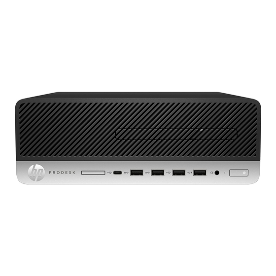
Drive configuration may vary by model. Some models have a bezel blank covering the slim optical drive bay. Front panel components Slim optical drive (optional) USB 2.0 port with HP Sleep and Charge SD card reader (optional) Audio-out (headphone)/Audio-in (microphone) combo jack... -
Page 9: Rear Panel Components
Power cord connector NOTE: Your model may have additional optional ports available from HP. When a device is plugged into either audio jack, a dialog box will appear on the monitor screen asking if you want to use the jack for a microphone or a headphone. You can also reconfigure the jacks at any time by double-clicking the Audio Manager icon in the Windows taskbar. -
Page 10: Non-Vpro Systems
Power cord connector NOTE: Your model may have additional optional ports available from HP. When a device is plugged into either audio jack, a dialog box will appear on the monitor screen asking if you want to use the jack for a microphone or a headphone. You can also reconfigure the jacks at any time by double-clicking the Audio Manager icon in the Windows taskbar. -
Page 11: Hardware Upgrades
The Safety & Comfort Guide also provides important electrical and mechanical safety information. The Safety & Comfort Guide is available on the Web at http://www.hp.com/ergo. WARNING! Energized and moving parts inside. -
Page 12: Removing The Computer Access Panel
Removing the computer access panel To access internal components, you must remove the access panel. Remove/disengage any security devices that prohibit opening the computer. Remove all removable media, such as compact discs or USB flash drives, from the computer. Turn off the computer properly through the operating system, and turn off any external devices. Disconnect the power cord from the AC outlet and disconnect any external devices. -
Page 13: Replacing The Computer Access Panel
Replacing the computer access panel Be sure that the access panel release lever is locked into place, and then place the access panel on the computer (1) and slide the panel forward (2). The release lever will automatically move back to the left and secure the access panel. -
Page 14: Removing The Front Bezel
Removing the front bezel Remove/disengage any security devices that prohibit opening the computer. Remove all removable media, such as compact discs or USB flash drives, from the computer. Turn off the computer properly through the operating system, and turn off any external devices. Disconnect the power cord from the AC outlet and disconnect any external devices. -
Page 15: Removing A Slim Optical Drive Bezel Blank
Removing a slim optical drive bezel blank On some models, a bezel blank covers the slim optical drive bay. Remove the bezel blank before installing an optical drive. To remove the bezel blank: Remove the computer access panel and front bezel. Then press inward on the tab on the left side of the blank (1), and then rotate the blank off the front bezel (2). -
Page 16: Removing And Installing The Optional Front Bezel Dust Filter
NOTE: The optional front bezel dust filter is available from HP. To remove, clean, and replace the dust filter: Turn off the computer properly through the operating system, and turn off any external devices. - Page 17 To replace the dust filter, press the filter firmly onto the front bezel at the tab locations shown below. Reconnect the power cord and any external devices, and then turn on the computer. Removing and installing the optional front bezel dust filter...
-
Page 18: Changing From Desktop To Tower Orientation
The Small Form Factor computer can be used in a tower orientation with an optional tower stand that can be purchased from HP. NOTE: To stabilize the computer in a tower orientation, HP recommends the use of the optional tower stand. Remove/disengage any security devices that prohibit moving the computer. -
Page 19: System Board Connections
System board connections Refer to the following illustration and table to identify the system board connectors for your model. Item System board connector System board label Color Component PCI Express x16 X16PCIEXP Black Expansion card PCI Express x4 X4PCIEXP Black Expansion card Battery Black... -
Page 20: Upgrading System Memory
Upgrading system memory The computer comes with double data rate 4 synchronous dynamic random access memory (DDR4-SDRAM) dual inline memory modules (DIMMs). The memory sockets on the system board are populated with at least one preinstalled memory module. To achieve the maximum memory support, you can populate the system board with up to 64 GB of memory configured in a high-performing dual-channel mode. - Page 21 DIMM and one 1 GB DIMM, and Channel B should be populated with the other two 1 GB DIMMs. With this configuration, 4 GB will run as dual-channel and 1 GB will run as single-channel. In any mode, the maximum operational speed is determined by the slowest DIMM in the system. ●...
- Page 22 Remove the drive cage. Push the release lever on the left side of the cage inward (1), lift the left side of the cage up (2), and then slide the right side of the cage out of the chassis (3). Open both latches of the memory module socket (1), and insert the memory module into the socket (2).
- Page 23 Replace the drive cage. Slide the tabs on the right side of the drive cage into the slots on the chassis (1), and then press the left side of the drive cage down onto the chassis (2). Reconnect the power and data cables to all drives in the drive cage. Replace the front bezel.
-
Page 24: Removing Or Installing An Expansion Card
Removing or installing an expansion card The computer has one PCI Express x4 expansion socket and one PCI Express x16 expansion socket. NOTE: The PCI Express sockets support only low profile cards. You can install a PCI Express x1, x4, x8, or x16 expansion card in the PCI Express x16 socket. For dual graphics card configurations, the first (primary) card must be installed in the PCI Express x16 socket. - Page 25 If you are removing a PCI Express x4 card, hold the card at each end and carefully rock it back and forth until the connectors pull free from the socket. Lift the card straight up (1) then away from the inside of the chassis (2) to remove it.
- Page 26 If you are removing a PCI Express x16 card, pull the retention arm on the back of the expansion socket away from the card (1) and carefully rock the card back and forth until the connectors pull free from the socket. Lift the card straight up (2) then away from the inside of the chassis (3) to remove it.
-
Page 27: Drive Positions
Rotate the slot cover retention latch back in place to secure the expansion card. Connect external cables to the installed card, if needed. Connect internal cables to the system board, if needed. Replace the computer access panel. If the computer was on a stand, replace the stand. Reconnect the power cord and any external devices, and then turn on the computer. -
Page 28: Removing And Installing Drives
Removing and installing drives When installing drives, follow these guidelines: The primary Serial ATA (SATA) hard drive must be connected to the dark blue primary SATA connector on ● the system board labeled SATA0. Connect an optical drive to the light blue SATA connector on the system board labeled SATA1. ●... -
Page 29: Removing A 9.5 Mm Slim Optical Drive
Removing a 9.5 mm slim optical drive Remove/disengage any security devices that prohibit opening the computer. Remove all removable media, such as compact discs or USB flash drives, from the computer. Turn off the computer properly through the operating system, and turn off any external devices. Disconnect the power cord from the AC outlet and disconnect any external devices. - Page 30 Push the green release latch on the right rear side of the drive toward the center of the drive (1), and then slide the drive forward and out of the bay (2). Chapter 2 Hardware upgrades...
-
Page 31: Installing A 9.5 Mm Slim Optical Drive
Installing a 9.5 mm slim optical drive Remove/disengage any security devices that prohibit opening the computer. Remove all removable media, such as compact discs or USB flash drives, from the computer. Turn off the computer properly through the operating system, and turn off any external devices. Disconnect the power cord from the AC outlet and disconnect any external devices. - Page 32 Slide the optical drive through the front bezel all the way into the bay (1) so that the latch on the rear of the drive locks into place (2). Connect the power cable (1) and data cable (2) to the rear of the drive. Connect the opposite end of the data cable to the light blue SATA connector on the system board labeled SATA1.
-
Page 33: Removing And Replacing A 3.5-Inch Hard Drive
Removing and replacing a 3.5-inch hard drive NOTE: Before you remove the old hard drive, be sure to back up the data from the old hard drive so that you can transfer the data to the new hard drive. Remove/disengage any security devices that prohibit opening the computer. Remove all removable media, such as compact discs or USB flash drives, from the computer. - Page 34 If replacing a 3.5-inch hard drive, transfer the mounting screws from the old hard drive to the new hard drive. You can purchase extra mounting screws from HP. Install four silver-and-blue 6-32 mounting screws (two on each side of the drive).
- Page 35 Secure the drive to the bay adapter bracket by installing four black M3 adapter bracket screws — through the underside of the bracket and into the drive. Removing and installing drives...
- Page 36 Install four 6-32 silver-and-blue mounting screws in the adapter bracket (two on each side of — the bracket). Align the mounting screws with the slots on the chassis drive cage, press the hard drive down into the bay, and then slide the drive back until it stops and locks in place. Chapter 2 Hardware upgrades...
-
Page 37: Removing And Installing An M.2 Ssd Storage Card
Connect the data cable (1) and power cable (2) to the rear of the hard drive. NOTE: The data cable for the primary hard drive must be connected to the dark blue connector on the system board labeled SATA0 to avoid any hard drive performance problems. Replace the computer access panel. - Page 38 Remove the drive cage. Push the release lever on the left side of the cage inward (1), lift the left side of the cage up (2), and then slide the right side of the cage out of the chassis (3). To remove an M.2 SSD card, remove the screw that secures the card (1), lift the end of the card up (2), and then slide the card out of the system board connector (3).
- Page 39 To install an M.2 SSD card, slide the pins on the card into the system board connector while holding the card at approximately a 30° angle (1). Press the other end of the card down (2), and then secure the card with the screw (3).
-
Page 40: Installing A Security Lock
Installing a security lock The security locks displayed below and on the following pages can be used to secure the computer. Cable lock Padlock Chapter 2 Hardware upgrades... -
Page 41: Hp Business Pc Security Lock V2
HP Business PC Security Lock V2 The HP PC Security Lock V2 is designed to secure all of the devices at your workstation. Attach the security cable fastener to a desktop using the appropriate screws for your environment (screws not provided) (1), and then snap the cover onto the base of the cable fastener (2). - Page 42 Slide the security cable through the security cable fastener. Pull the two scissor hands of the monitor lock apart and insert the lock into the security slot on the rear of the monitor (1), close the scissor hands together to secure the lock in place (2), and then slide the cable guide through the center of the monitor lock (3).
- Page 43 Slide the security cable through the security guide installed on the monitor. Attach the accessory cable fastener to a desktop using the appropriate screw for your environment (screw not provided) (1), and then place the accessory cables into the base of the fastener (2). Installing a security lock...
- Page 44 Slide the security cable through the holes in the accessory cable fastener. Screw the lock to the chassis using the screw provided. Chapter 2 Hardware upgrades...
- Page 45 Insert the plug end of the security cable into the lock (1) and push the button in (2) to engage the lock. Use the key provided to disengage the lock. When you have completed all steps, all of the devices at your workstation will be secured. Installing a security lock...
-
Page 46: Appendix A Battery Replacement
The lifetime of the lithium battery can be extended by plugging the computer into a live AC outlet. The lithium battery is only used when the computer is NOT connected to AC power. HP encourages customers to recycle used electronic hardware, HP original print cartridges, and rechargeable batteries. For more information about recycling programs, go to http://www.hp.com/recycle. - Page 47 Slide the replacement battery into position, positive side up. The battery holder automatically secures the battery in the proper position. Type 2 To release the battery from its holder, squeeze the metal clamp that extends above one edge of the battery. When the battery pops up, lift it out (1). To insert the new battery, slide one edge of the replacement battery under the holder’s lip with the positive side up.
- Page 48 Insert the new battery and position the clip back into place. NOTE: After the battery has been replaced, use the following steps to complete this procedure. Replace the computer access panel. If the computer was on a stand, replace the stand. Reconnect the power cord and any external devices, and then turn on the computer.
-
Page 49: Appendix B Electrostatic Discharge
● Use a portable field service kit with a folding static-dissipating work mat. ● If you do not have any of the suggested equipment for proper grounding, contact an HP authorized dealer, reseller, or service provider. NOTE: For more information on static electricity, contact an HP authorized dealer, reseller, or service provider. -
Page 50: Appendix C Computer Operating Guidelines, Routine Care And Shipping Preparation
Computer operating guidelines, routine care and shipping preparation Computer operating guidelines and routine care Follow these guidelines to properly set up and care for the computer and monitor: Keep the computer away from excessive moisture, direct sunlight, and extremes of heat and cold. ●... -
Page 51: Optical Drive Precautions
● Safety If any object or liquid falls into the drive, immediately unplug the computer and have it checked by an authorized HP service provider. Shipping preparation Follow these suggestions when preparing to ship the computer: Back up the hard drive files to an external storage device. Be sure that the backup media is not exposed to electrical or magnetic impulses while stored or in transit. -
Page 52: Appendix D Accessibility
Accessibility HP designs, produces, and markets products and services that can be used by everyone, including people with disabilities, either on a stand-alone basis or with appropriate assistive devices. Supported assistive technologies HP products support a wide variety of operating system assistive technologies and can be configured to work with additional assistive technologies. -
Page 53: Index
9 security removal 6 hard drive 27 cable lock 34 replacement 7 M.2 SSD card 31 HP Business PC Security Lock 35 accessibility 46 memory 14 padlock 34 slim optical drive 25 serial number location 4 shipping preparation 45...
Need help?
Do you have a question about the ProDesk 600 G3 SFF Business PC and is the answer not in the manual?
Questions and answers