
Subscribe to Our Youtube Channel
Related Manuals for Shuttle HOT-555


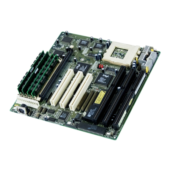
Summary of Contents for Shuttle HOT-555
- Page 1 HOT-555 Pentium processor ™ Based PCI MAIN BOARD User's Manual HOT-555 User's Manual 1...
- Page 2 FCC Notice: This equipment has been tested and found to comply with the limits for a Class B digital device, pursuant to Part 15 of FCC Rules. These limits are designed to provide reasonable protection against harmful interference in a residential installation.
-
Page 3: Table Of Contents
The Main Menu....................1 6 Standard CMOS Setup..................1 8 BIOS Features Setup ..................2 0 Chipset Features Setup..................2 2 Power Management Setup................2 5 PCI Configuration Setup................. 2 7 Integrated Peripherals..................2 9 Password Setting....................3 1 HOT-555 User's Manual 3... -
Page 4: Preface
72-pin SIMM socket and 168-pin DIMM socket. A type 7 Pentium processor socket provides access to future processor enhancements. HOT-555 provides a new level of I/O integration. Intel's 82430VX PCIset chipset provides increased integration and improved performance over other chipset designs. -
Page 5: Chapter 1 Introduction
Integrated L2 write-back cache controller - 256KB Direct Mapped Pipeline Burst Cache Power Management Function Provides four power management modes : Full on, Doze, Standby, and Suspend Supports Microsoft APM Provides EPMI (External Power Management Interrupt) pin HOT-555 User's Manual 5... - Page 6 Port), EPP (Enhanced Parallel Port), and ECP (Extended Capabilities Port) high performance parallel port. Two serial ports - Supports 16C550 compatible UARTS. - Supports IrDA (Infra-red) communication. One PS/2 mouse port USB (Universal Serial Bus) port Board Design Dimension 220mm x 230mm HOT-555 User's Manual 6...
-
Page 7: Nstallation
Hardware Installation Chapter Jumpers HOT-555 User's Manual 7... -
Page 8: Cpu Clock Speed Selection
Jumpers JP27 and JP28 determine the system clock frequency from 50MHz to 66MHz. HOT-555 mainboard also provides Jumpers JP23 and JP24 to figure up CPU core clock multiplier. By inserting or removing jumper caps on JP23 and JP24, the user can change the Host Bus Clock/CPU Core Clock ratio from 1 : 1.5 to 1 : 3. -
Page 9: Onboard Regulator Output Selection - Jp4, 10, 13, 36
Onboard Regulator Output Selection - JP4, 10, 13, 36 HOT-555 mainboard is designed an onboard voltage regulator to provide single 3.3V voltage ranger (V ) for Intel Pentium P54C, Cyrix CORE 6x86 and AMD5k86 processors, and also provide dual 3.3/2.5V voltage... -
Page 10: Flash Eprom Jumper - Jp18
Flash EPROM Jumper - JP18 HOT-555 mainboard supports two types of flash EPROM, 5 volt and 12 volt. By setting up jumper JP18, you can update both types of flash EPROM with new system BIOS files as they come available. -
Page 11: Clear Password - Jp9
On-board Enhanced Connector J10, Universal Serial (USB) Connectors J P 3 IrDA Communication Port Connector J P 1 Cooling Connector Display type (Color/Mono) Switcher Open Monochrome J P 7 Close EGA/CGA VGA display card don't care HOT-555 User's Manual 11... -
Page 12: Chapter 3 Memory Configuration
Memory Configuration Chapter The HOT-555 mainboard provides four 72-pin SIMM sockets and two 168- pin DIMM sockets that make it possible to install up to 128MB of RAM. The SIMM socket support 4MB, 8MB, 16MB, and 32MB single- or double- side fast page or EDO DRAM modules. - Page 13 16 MB 32 MB 32 MB 104 MB 4 MB 32 MB Empty Not Available 72 MB 4 MB 32 MB 8 MB Not Available 80 MB 4 MB 32 MB 32 MB Not Available 104 MB HOT-555 User's Manual 13...
- Page 14 32 MB 32 MB Not Available Not Available 128 MB 32 MB Empty Not Available 8 MB 72 MB 32 MB Empty Not Available 16 MB 80 MB 32 MB Empty Not Available 32 MB 96 MB HOT-555 User's Manual 14...
-
Page 15: Award Bios Setup
Award BIOS Setup Chapter HOT-555's BIOS ROM has a built-in Setup program that allows users to modify the basic system configuration. This type of information is stored in battery-backed RAM so that it retains the Setup information when the power is turned off. -
Page 16: The Main Menu
PCI bus master and the IRQ level for PCI device. Power-on with BIOS defaults Load BIOS Defaults BIOS defaults loads the values required by the system for the maximum performance. However, you may change the parameter through the Option Setup Menu. HOT-555 User's Manual 16... - Page 17 Change, set, or disable user password. It allows you to limit access to the system and Setup, or just to Setup. Save & Exit setup Save CMOS value change to CMOS and exit setup Exit without saving Abandon all CMOS value changes and exit setup. HOT-555 User's Manual 17...
-
Page 18: Standard Cmos Setup
If you select Type User, related information is asked to be entered to the following items. Enter the information directly from the keyboard and press <Enter>. Those information should be provided in the documentation from your hard disk vendor or the system manufacturer. HOT-555 User's Manual 18... - Page 19 640K for systems with 640K or more memory installed on the mainboard. Extended Memory The BIOS determines how much extended memory is present during the POST. This is the amount of memory located above 1MB in the CPU's memory address map. HOT-555 User's Manual 19...
-
Page 20: Bios Features Setup
When this category enables, the BIOS will swap floppy drive assignments so that Drive A: will function as Drive B: and Drive B: as Drive A:. Boot Up Floppy Seek During POST, BIOS will determine if the floppy disk drive installed is 40 or 80 tracks. HOT-555 User's Manual 20... - Page 21 If there over 64MB memory on your system, please set this category to OS2 for total memory detection under OS/2 operating system, otherwise set to Non-OS2. Video BIOS Shadow/XXXXX-XXXXX Shadow These categories determine whether Video BIOS or optional ROM will be copied to RAM. HOT-555 User's Manual 21...
-
Page 22: Chipset Features Setup
The options are 7/6 and 6/5 CLKs. Fast RAS To CAS Delay This category set the DRAM RAS to CAS Delay to controls the DRAM page miss and row miss leadoff timings. The options are 3 and 2 CLKs. HOT-555 User's Manual 22... - Page 23 33MHz, ISA Clock will be 8.25MHz when PCI clock divided by 4, and 11MHz when PCI clock divided by 3. System BIOS Cacheable This category allows the user to set whether the system BIOS F000~FFFF areas are cacheable or non-cacheable. HOT-555 User's Manual 23...
- Page 24 This category is used to enable a memory hole in DRAM space. CPU cycles matching an enabled hole are passed on to PCI. Note that a selected hole is not remapped. Peer Concurrency This category is used to defined PCI Concurrency is " E nable" or "Disable" setting. HOT-555 User's Manual 24...
-
Page 25: Power Management Setup
The system BIOS will only blanks off the screen Blank Screen when disabling video. V/H SYN addition to Blank Screen, BIOS will also turn +Blank off the V-SYNC & H-SYNC signals from VGA cards to monitor. DPMS HOT-555 User's Manual 25... - Page 26 IRQ 6 (Floppy Disk) IRQ 7 (LPT 1) IRQ 8 (RTC Alarm) IRQ 9 (IRQ 2 Redir) IRQ 10 (Reserved) IRQ 11 (Reserved) IRQ 12 (PS/2 Mouse) IRQ 13(Copro-) IRQ 14 (Hard Disk) IRQ 15 (Reserved) HOT-555 User's Manual 26...
-
Page 27: Pci Configuration Setup
IRQ4 default assign to legacy ISA for COM1. IRQ 5 assigned to The system BIOS will assign IRQ 5 to legacy ISA or PCI/ISA PnP. IRQ5 default assign to PCI/ISA PnP for PCI or ISA PnP devices. HOT-555 User's Manual 27... - Page 28 IRQ15 default assign to legacy ISA for secondary IDE controller. DMA-0, 1, 3, 5, 6, 7 assigned to The system BIOS will assign DMAs to legacy ISA or PCI/ISA PnP. DMA 0, 1, 3, 5, 6 and 7 channel default assign to PCI/ISA PnP. HOT-555 User's Manual 28...
-
Page 29: Integrated Peripherals
This category is used to defined on chip Primary PCI IDE controller is "Enable" or "Disable " setting. On-Chip Secondary PCI IDE This category is used to defined on chip Secondary PCI IDE controller is "Enable" or "Disable " setting. HOT-555 User's Manual 29... - Page 30 COM2/2F8H , COM3/3E8H , COM4/2E8H or Disabled . Infra Red (IR) Function HOT-555 main board support IrDA(HPSIR) and Amplitudes Shift Keyed IR(ASKIR) infrared through COM 2 port. This category specifies onboard Infra Red mode to HPSIR, ASKIR or Disabled .
-
Page 31: Password Setting
To disable password, just press <Enter> when you are prompted to enter password. A message will confirm the password being disabled. Once the password is disabled, the system will boot and you can enter Setup freely. HOT-555 User's Manual 31... - Page 32 Warning : Retain a safe record of your password. If you've forgotten or loosed the password, the only way to access the system is to clear CMOS memory, please refer to "Clear CMOS" or "Clear Password" section. HOT-555 User's Manual 32...
Need help?
Do you have a question about the HOT-555 and is the answer not in the manual?
Questions and answers