TESTO 480 Instruction Manual
Climate measuring instrument
Hide thumbs
Also See for 480:
- Instruction manual (58 pages) ,
- Short manual (10 pages) ,
- Instruction manual (52 pages)

Related Manuals for TESTO 480


Summary of Contents for TESTO 480
- Page 1 480 · Climate measuring instrument Instruction manual 99 Washington Street Melrose, MA 02176 Phone 781-665-1400 Toll Free 1-800-517-8431 Visit us at www.TestEquipmentDepot.com...
-
Page 3: Table Of Contents
1 Contents Contents Contents ....................3 Safety and the environment ..............5 2.1. About this document ................ 5 2.2. Ensure safety ................... 6 2.3. Protecting the environment .............. 7 Specifications ..................8 3.1. Use ....................8 3.2. Technical data ................. 8 Product description ................ - Page 4 1 Contents 6.6.11. PMV/PPD measurement ................42 6.6.12. Saving measurement values ................46 6.6.13. Printing measurement values ................ 48 6.6.14. Display measuring values graphically ............49 6.6.15. Transferring measurement values ..............50 Maintaining the product ............... 51 7.1.1. Battery care ....................51 7.1.2.
-
Page 5: Safety And The Environment
2 Safety and the environment Safety and the environment 2.1. About this document Symbols and writing standards Representation Explanation Warning advice, risk level according to the signal word: Warning! Serious physical injury may occur. Caution! Slight physical injury or damage to the equipment may occur. -
Page 6: Ensure Safety
Follow the prescribed steps exactly. Use only original spare parts from Testo. > Temperatures given on probes relate only to the measuring range of the sensors. Do not expose handles and feed lines to temperatures in excess of 40 °C (104 °F), unless they are... -
Page 7: Protecting The Environment
> Dispose of faulty rechargeable batteries/spent batteries in accordance with the valid legal specifications. > At the end of its useful life, send the product to the separate collection for electric and electronic devices (observe local regulations) or return the product to Testo for disposal. -
Page 8: Specifications
3 Specifications Specifications 3.1. The testo 480 is a measuring instrument for measuring climate- related parameters. The testo 480 is ideal for comfort level measurements for the workplace evaluation and flow measurements in and at ventilation and air-conditioning systems. The instrument is only to be used by qualified expert personnel. - Page 9 3 Specifications Feature Values Measuring cycle 0.5 s Operating 0 to +40 °C temperature Storage temperature -20 to +60 °C Dimensions 81 mm x 235 mm x 39 mm Housing material ABS, TPE, PMMA Weight Approx. 435 g IP protection class 30 (with connected probes) Integrated measurement (at 22 °C, ±1 digit) Feature...
- Page 10 Standards, tests, warranty Feature Values EU Directive 2004/108/EC Vibration IEC 60068-2-6 Warranty 2 years, warranty conditions: see www.testo.com/warranty Mains unit (0554 8808) for continuous measurements and battery charging Feature Values Output voltage 5 V / 4 A EU Directive 2004/108/EC...
- Page 11 0 – 40 °C / 32 – 104 °F Long-term storage <23 °C / <73 °F temperature EU Directive 2004/108/EC Warranty period 2 years, warranty conditions: see www.testo.com/warranty Test Equipment Depot - 800.517.8431 99 Washington Street, Melrose, MA 02176 TestEquipmentDepot.com...
-
Page 12: Product Description
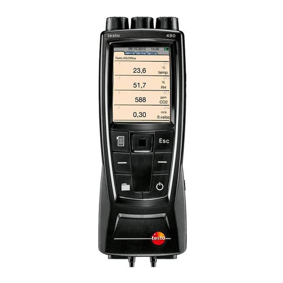
4 Product description Product description 4.1. Overview 4.1.1. Hand instrument 1 Display 2 Mini USB interface (right-hand side of instrument) 3 Control buttons and trackpad (navigation field) 4 SD card slot (right-hand side of instrument) 5 Magnetic holder (on back) WARNING Magnetic field May be harmful to those with pacemakers. -
Page 13: Instrument Connections And Interfaces
4.1.2. Instrument connections and interfaces 1 Probe sockets for digital probes 2 IR interface for printouts with testo report printer (art. no. 0554 0549) CAUTION Risk of injury from infrared beam! > Do not direct infrared beam at human eyes! -
Page 14: Controls
4 Product description Status Explanation LED off Rechargeable battery is not charging LED on, Rechargeable battery is charging lights up LED on, Rechargeable battery is not charging, flashes instrument/battery temperature too high slowly LED on, Rechargeable battery is not charging, battery flashes faulty quickly... -
Page 15: Display
4 Product description 4.1.4. Display Status line and tabs 1 Status bar (dark grey background): Icon Explanation There is no SD card in the instrument Printing Date and time Battery operation Indication of remaining capacity of the rech. batt. by the colour and fill level of the battery symbol (green = 5-100%, red = <... - Page 16 4 Product description 3 Info field of register tabs: display of the selected measuring location/measuring point. The displayed measuring point can be selected in Explorer, see Explorer menu, page 28. Measuring view 1 Line number 2 Measurement value 3 Indication that the measurement value is also displayed in the Favourites tab.
-
Page 17: First Steps
5.1. Commissioning Initial charging of rechargeable battery The testo 480 is delivered with a partially charged battery. Charge the battery fully before using it for the first time. 1. Connect the mains unit to the mains socket (3). 2. Connect the mains plug to a power socket. - Page 18 5 First steps → Save and close. The current measurement values are displayed. The instrument is now operational. Switching off Unsaved measurement values are lost when the instrument is switched off. > Switch the instrument off with Connecting probes / sensors Probes are detected automatically by the instrument.
-
Page 19: Getting To Know The Product
5 First steps Connecting the mains unit If the mains unit is connected, the instrument is powered automatically via the mains unit. When power is supplied via the mains unit, the instrument may heat up. This may increase the measurement uncertainty during TC measurement. -
Page 20: Calling Up A Function
5 First steps → Min/Max. Short form → Display Steps 1. Open Main 2. Select 4. Select required Display Min/Max menu: menu: menu: 3. Confirm 5. Confirm selection: selection: 5.2.2. Calling up a function 1. Select function: A box appears around the selected function. 2. -
Page 21: Entering Values
5 First steps 5.2.5. Entering values Some functions require values (numbers, units, characters) to be entered. Depending on the function that is chosen, the values are entered via either a list field or an input editor. List field 1. Select the value to be changed (numerical value, unit): (depending on the selected function). -
Page 22: Saving Values
5 First steps 2. Accept value: Options: > Toggle between upper / lower case characters: Select > Toggle between characters and numbers: select > Insert space: select > Delete character in front of cursor: select 3. Repeat steps 1 and 2 as required. 4. -
Page 23: Using The Product
Change/deactivate password • Probe name If you forget the password, it can only be reset by Testo Service Password protection is not set as default. Units It is possible to toggle between ISO and US units. The setting only relates to the unit of the measured parameters, not to the calculated parameters. -
Page 24: Setting The Measurement Display
6 Using the product Symbol Explanation Norm data The temperature and absolute pressure values for the internal calculation of the standard flow rate can be changed. Factory-set: 25 °C, 1013.25 hPa Pressure settings Selection of the additional information that should be included on a measurement value printout. -
Page 25: Calculated Measurement Parameters
6 Using the product Representation Explanation Parameter display The individual lines can be changed in the parameter display: • Changing measurement parameters and units: Select line • Move/delete/insert lines • Copy lines to Favourites tab Lines displayed on the Favourites tab are indicated with a tick. -
Page 26: Favourites Tab
6 Using the product Dewpoint Temperature at which condensation of the water vapour in the gas occurs. Psychrometer temperature (pressure-dependent) Wet-bulb temperature of a psychrometer. It is used to calculate the absolute pressure entered under norm data Enthalpy Heat content of the measured gas. Unit kJ/kg or BTU/lb. Absolute humidity Describes how many grams of water are contained in a cubic metre of the currently measured gas. - Page 27 6 Using the product Symbol Explanation Probe info Probe name, serial number and probe type are displayed. Probe name Probe name can be edited. Adjustment info The probe-specific adjustment data saved on the probe can be displayed. The digital probes allow direct measurement and signal conversion in the probe.
-
Page 28: Explorer Menu
6 Using the product 6.5. Explorer menu In Explorer, all saved measurement values are displayed with the assigned data like the measuring program and customer data in a set structure. Measurement values that were not saved are lost when the measuring instrument is switched off! Calling up the Explorer view >... - Page 29 6 Using the product Measuring point (e.g. ventilation shaft 1) documenting the location description with measurement-related parameters, e.g. cross- sections. A measuring point can have several measuring programs. Measuring program documenting the measuring process and the start and stop criteria for the measurement (e.g.
- Page 30 6 Using the product Creating a new location A location is always created in a folder. 1. Select the folder in which the location is to be created. → New measuring location. 3. Enter values. → 4. Finalise the entry: Save and close.
-
Page 31: Measurements & Measuring Programs
6 Using the product → > New PMV/PPD measurement: Carrying out a PMV/PPD measurement, see PMV/PPD measurement, page → > New WBGT measurement: Carrying out a WBGT measurement, see WBGT measurement, page 41. For creating a new measuring program, see Measuring program, page 32 6.6. -
Page 32: Measuring Program
6 Using the product 6.6.3. Measuring program You can customise measuring programs to match the relevant measuring task (e.g. continuous or punctual measurement). These measuring programs are linked to a specific measuring point. After the measurement, the relevant measurement protocols are saved under the measuring program. - Page 33 6 Using the product Parameter Explanation • End criterion Manual: Measurement is ended via → End. • Date/Time: Measurement ends at a set time. • Duration: measurement ends after a set duration has lapsed. • Number of values: measurement ends after a sequence of measured values.
-
Page 34: Grid Measurement
Detailed background information on grid measurement and carrying it out can be found in the Testo Ambient Air Measurement for Practical Users field guide. You can request a free copy or download it from www.testo.com. - Page 35 Layout Measuring The number of measuring points depends on points the distance from the point of discontinuity and irregularities in the profile. More information can be found in the Testo "Ambient Air Measurement for Practical Users" field guide.
- Page 36 6 Using the product Hole position Select any hole position with depending on channel accessibility. Edge spacing For example, damping of the channel wall can be taken into consideration. Entered values influence the coordination of the measuring points. Uncertainties Estimated uncertainty of the channel Channel dimensions.
- Page 37 6 Using the product 3. Repeat steps 1 and 2 until all points have been measured. The individual velocity measurement values are used to calculate the mean flow velocity, from which the volumetric air flow is then calculated. If high differences in flow velocities are ascertained over the cross-section, the number of measuring points is to be increased.
-
Page 38: Turbulence Measurement
6 Using the product 6.6.5. Turbulence measurement A connected turbulence probe 0628 0143 enables the turbulence to be calculated for the flow value in accordance with DIN EN 13779. The turbulence probe 0628 0143 has an internal absolute pressure sensor used to carry out automatic compensation. There is no need to enter an absolute pressure value here. -
Page 39: Measurement With The Funnel
The Pitot factor for Pitot tubes is generally the same and must be entered: • Pitot tubes from Testo 1.00 • Straight Pitot tubes, Pitot factor: 0.67 For Pitot tubes from other manufacturers, the Pitot factor can be found in the instruction manual or you should ask your supplier. -
Page 40: Pressure Measurement
Ø 8,5cm. For carrying out the measurement, see Measuring program, page 6.6.8. Pressure measurement The testo 480 has an internal absolute and differential pressure sensor. The pressure measurement values are therefore displayed on the tab. 1. Connect pressure tubes for differential pressure measurement (2) to + and -. -
Page 41: Co 2 Measurement
6 Using the product 6.6.9. measurement • The CO probe measures the absolute pressure. The displayed value is compensated automatically in line with the absolute pressure. • Due to the sensor, the probe has a relatively high power consumption. For continuous measurements, use a mains unit for the power supply. -
Page 42: Pmv/Ppd Measurement
Percentage Dissatisfied) e.g. at workstations and is described in the ISO 7730. The mean radiation temperature required for determining PMV/PPD is calculated in the testo 480 from the measurement parameters of globe temperature, ambient temperature and air speed. The formula is based on forced convection and applies to standard bulbs with 150 mm diameter. - Page 43 6 Using the product Necessary measuring values • Mean radiation temperature in °C = t • Globe temperature in °C = t • Ambient temperature in °C = t • Air speed in tr = [(tg+273)4+2.5*108*va0.6*(tg-ta)]1/4-273 Factors to be entered •...
- Page 44 6 Using the product Parameter Parameter in Explanation in clo m2K/W 2.30 – 2.79 0.356 – 0.432 Warm winter clothing 2.80 – 3.00 0.433 – 0.465 Extremely warm winter clothing Input parameters for activity Parameter Parameter in Explanation in met W/m2 0.1 –...
- Page 45 6 Using the product Performing a measurement ✓ All points under "Preparing for measurement" have been carried out. 1. Press Explorer structure is displayed. 2. Select the desired measuring point. → New PPMV/PPD measurement. PMV/PPD measurement is opened. 4. Select ID numbers of the individual probes. 5.
-
Page 46: Saving Measurement Values
6 Using the product 6.6.12. Saving measurement values All measurement protocols displayed in Explorer are saved in the internal instrument memory. Saving measurement values on an SD card 1. Insert SD card. Only SD cards with max. 2 GB space can be used. 2. - Page 47 6 Using the product 1. Insert SD card. Only SD cards with max. 2 GB space can be used. 2. Select root folder in the Explorer view. → Import. A list of importable data is displayed. 4. Select the required entry. An import message is displayed.
-
Page 48: Printing Measurement Values
23. From measuring mode ✓ testo printer (0554 0549) has been switched on. ✓ Required tab has been selected. 1. Align IR interfaces testo 480 and testo printer. → Print. 2. Select The set measuring view and are displayed. -
Page 49: Display Measuring Values Graphically
6 Using the product 6.6.14. Display measuring values graphically Measuring values of max. four measurement parameters can be displayed as a colour graphic over a period of 110 seconds. In the case of longer time frames, the oldest values are deleted and replaced by the new ones. -
Page 50: Transferring Measurement Values
As soon as the instrument is disconnected from the PC, it can be operated again via the control keys. 3. For carrying out an instrument readout via testo EasyClimate software and processing data, see separate testo EasyClimate software instrument manual. -
Page 51: Maintaining The Product
The Testo adjustment set provides a reference value to calculate the offset for a humidity adjustment. Humidity adjustment is possible with the following probes: •... -
Page 52: Carrying Out A Firmware Update
5. Carry out adjustment for the second adjustment point. 7.1.3. Carrying out a firmware update Updated firmware can be installed on the instrument. A firmware update can also be carried out with testo EasyClimate. ✓ Instrument is switched on. 1. Download the current firmware file from www.testo.com/download-center (registration required). - Page 53 7 Maintaining the product 4. Copy unzipped firmware file and folder to Update folder. 5. Log out instrument from Windows (safely remove hardware). 6. Unplug USB cable. 7. Switch the instrument off. 8. Switch the instrument on. Firmware has been updated.
-
Page 54: Tips And Assistance
>10 sec. pressed. The instrument is switched off. 2. Switch instrument on with If we could not answer your question, please contact your dealer or Testo Customer Service. For contact data, see back of this document or website www.testo.com/service-contact. -
Page 55: Accessories And Spare Parts
340 mm/330 x 330 mm, incl. case Testovent 415, flow rate funnel, Ø 0554 0415 210 mm/190 x 190 mm, incl. case Testo high speed printer with wireless 0554 0549 infrared interface, 1 roll of thermal paper and 4 AA batteries... - Page 56 Test Equipment Depot - 800.517.8431 99 Washington Street, Melrose, MA 02176 TestEquipmentDepot.com 0970 4800 en 05 V01.05 en-GB...
Need help?
Do you have a question about the 480 and is the answer not in the manual?
Questions and answers