Table of Contents
Advertisement
Simultaneous
Interpretation
Conference System
Operating Instructions
Before operating the unit, please read this manual thoroughly
and retain it for future reference.
SX-M700A
SX-C700A/C750
SX-D700A/D750
SX-P700
Interpreter's Unit
2001 Sony Corporation
Control Unit
Chairman's Unit
Delegate's Unit
3-206-661-11
(3)
Advertisement
Table of Contents

Subscribe to Our Youtube Channel
Related Manuals for Sony SX-M700A


Summary of Contents for Sony SX-M700A
- Page 1 3-206-661-11 Simultaneous Interpretation Conference System Operating Instructions Before operating the unit, please read this manual thoroughly and retain it for future reference. SX-M700A Control Unit SX-C700A/C750 Chairman’s Unit SX-D700A/D750 Delegate’s Unit SX-P700 Interpreter’s Unit 2001 Sony Corporation...
- Page 2 The model and serial numbers are located on the rear of the This equipment has been tested and found to comply with SX-M700A and on the bottom of the SX-C700A/C750/ the limits for a Class A digital device, pursuant to Part 15 of D700A/D750/P700.
- Page 3 NOTICE FOR THE CUSTOMERS IN THE For the customers in Europe This product with the CE marking complies with both the UNITED KINGDOM EMC Directive (89/336/EEC) and the Low Voltage Directive (73/23/EEC) issued by the Commission of the European WARNING Community.
-
Page 5: Table Of Contents
Outline ...................... 6 Features ......................6 System Configuration ..................7 Location and Function of Parts and Controls ........8 SX-M700A Control Unit ................8 SX-C700A/C750/SX-D700A/D750 Chairman’s Unit/Delegate’s Unit ..11 SX-P700 Interpreter’s Unit ................14 Setting Up the System ................16 Precautions .................... -
Page 6: Outline
Outline Features The SX-M700A simultaneous interpretation In addition to the units described above, the following conference system is designed to allow delegates’ optional units are available. speeches to be interpreted into a maximum of six SXA-120 Expansion Board languages. Delegates in a conference hall can thus The board is designed to allow the expansion of the listen to any of the interpreted languages. -
Page 7: System Configuration
System Configuration The figure below shows an example of the simultaneous interpretation system. Conference hall Operator section Conference seats SX-M700A Control Unit SXA-120 SX-C700A Chairman’s Unit Expansion SX-GS10 Board Conference Management Software Interpreter’s booth DX-D700A Delegate’s Unit SX-P700 Interpreter’s Unit... -
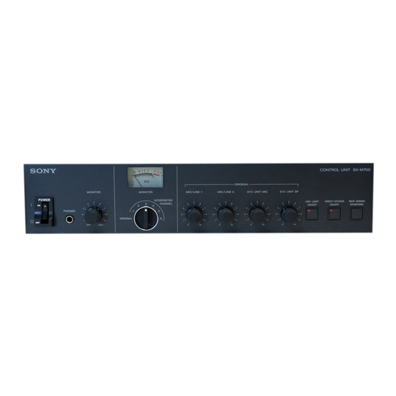
Page 8: Location And Function Of Parts And Controls
Location and Function of Parts and Controls SX-M700A Control Unit Front panel ORIGINAL volume controls POWER switch MIC LIMIT ON/OFF button PHONES connector DIRECT ACCESS MONITOR volume control ON/OFF button MONITOR channel selector SEAT ASSIGN Level meter START/END button Rear panel... - Page 9 8DIRECT ACCESS ON/OFF button 5Level meter Not used. Indicates the output level of the audio signal selected by the MONITOR channel selector 4. When the 9SEAT ASSIGN START/END button MONITOR channel selector is set to ORIGINAL, the Not used. level meter also indicates the level of the original sound output to the LINE OUT qs, AUDIO IN/OUT 0EXT UNIT IN/OUT (external unit input/ qd, and INTERPRETER’S UNIT qg connectors.
- Page 10 Location and Function of Parts and Controls qsLINE OUT (line output) connectors (phono qhDELEGATE’S/CHAIRMAN’S UNIT jacks) connectors (20-pin multi-connectors) Supply the original signal from the chairman’s unit/ Connect to the SX-C700A/C750/SX-D700A/D750 delegate’s unit, that from the rostrum or conference Chairman’s Unit/Delegate’s Unit. The same signal is hall microphone, as well as the six channel output from four connectors.
-
Page 11: Sx-C700A/C750/Sx-D700A/D750 Chairman's Unit/Delegate's Unit
SX-C700A/C750/SX-D700A/D750 Chairman’s Unit/Delegate’s Unit The following two combinations of the chairman’s This section explains the location and function of unit and delegate’s unit are available for use with the parts and controls of the chairman’s unit and system. delegate’s unit. The explanation applies to both combinations. - Page 12 The microphone can be rotated freely. The the chairman’s unit/delegate’s unit placed opposite microphone operation depends on the setting of the the SX-M700A Control Unit and the next chairman’s MIC ON/OFF button 8. unit/delegate’s unit. For details, see the explanation of the MIC ON/OFF button...
- Page 13 The LIMIT ON/OFF button indicator does not light), pressing this button turns the microphone on. The speaker’s volume is adjusted from the SX-M700A Control Unit. To prevent howling, nothing is output MIC ON/OFF button indicator and microphone from the speaker when the microphone of the indicator 2 light.
-
Page 14: Sx-P700 Interpreter's Unit
Location and Function of Parts and Controls SX-P700 Interpreter’s Unit Front panel MICROPHONE CHANNEL buttons MICROPHONE CHANNEL buttons Microphone indicator Microphone indicator MONITOR selector MONITOR selector RELAY button RELAY button ORIGINAL button ORIGINAL button VOLUME control VOLUME control COUGH CUT button COUGH CUT button MICROPHONE ON button MICROPHONE OFF button... - Page 15 Press to monitor the original signal through the (not supplied). When the interpreter’s unit is placed headphones (the button lights). next to the SX-M700A Control Unit, connect to the INTERPRETER’S UNIT connector of the control RELAY button and ORIGINAL button unit.
-
Page 16: Setting Up The System
Power supply interpreter’s unit • Operate the unit only with a power source as The SX-M700A Control Unit is provided with four specified in “Specifications” section. DELEGATE’S/CHAIRMAN’S UNIT connectors and • Do not drop or place heavy objects on the power two INTERPRETER’S UNIT connectors. - Page 17 SX-D750 units can be connected to one line. The specially designed cables are used to connect these units to the system. For details, contact your Sony dealer. How to connect cables of SX-C700A/D700A The figure below shows how to connect and disconnect the 20-pin multi-connectors of the chairman’s/delegate’s unit, RK-1700/1705 and RK-...
-
Page 18: Turning On The Power Of The System
Setting Up the System Turning On the Power of the Preparing the Control Unit System Adjusting the audio level Adjust the audio signal output to the chairman’s/ delegate’s unit from external equipment connected to EXT IN-1/2 before the conference. Adjusting the output level of the audio signal to the chairman’s unit/delegate’s unit Control unit Level meter... - Page 19 Adjusting the input level of the audio signal Note from equipment connected to EXT IN-1/2 When the power of the control unit is turned off, the connectors MIC LIMIT ON/OFF button is automatically reset to OFF even if it has been set to ON. To set the mode to limit the number of speakers to five after the power of the control unit is turned on again, press the MIC LIMIT ON/OFF button such...
-
Page 20: Operation During A Conference
Operation During a Conference Operations Performed by the Chairman and Delegates To listen to the original signal Operations common to both the chairman Set the CH selector to ORIGINAL. The original and delegates signal is output to the earphone. Alternatively, The chairman and delegates can both talk and listen disconnect the earphone. -
Page 21: Interpreter's Operations
Interpreter’s Operations An interpreter uses an SX-P700 interpreter’s unit. The interpreter’s unit is designed to be used simultaneously by two interpreters. Confirming the channel of the interpreted language Confirm that the MICROPHONE CHANNEL button corresponding to the channel of an interpreter’s target language is lit before the start of the conference. - Page 22 Operation During a Conference MICROPHONE OFF button and the SLOW button are common to left and right blocks of the interpreter’s unit. Either of the two interpreters can use these buttons. Temporarily turning off the When the speaker speaks too quickly to microphone (cough cut) interpret Press the COUGH CUT button.
-
Page 23: Troubleshooting Guide
If the unit subsequently operates normally, communication power is turned on, the unit’s is resumed. indicator and button start If this problem occurs frequently, contact your nearest Sony blinking and do not go out, dealer. even after a few seconds. -
Page 24: Specifications
SX-C700A/C750 Chairman’s Unit Design and specifications are subject to change SX-D700A/D750 Delegate’s Unit without notice. Voting connector (6-pin) ×1 Input/Output SX-M700A Control Unit Input Input connector (for SX-C750/ D750 only) (D-sub 15-pin) ×1 Input/output DELEGATE’S /CHAIRMAN’S Earphone output (minijack) ×2...
Need help?
Do you have a question about the SX-M700A and is the answer not in the manual?
Questions and answers