Table of Contents
Advertisement
Quick Links
OWNER'S OPERATION AND INSTALLATION MANUAL
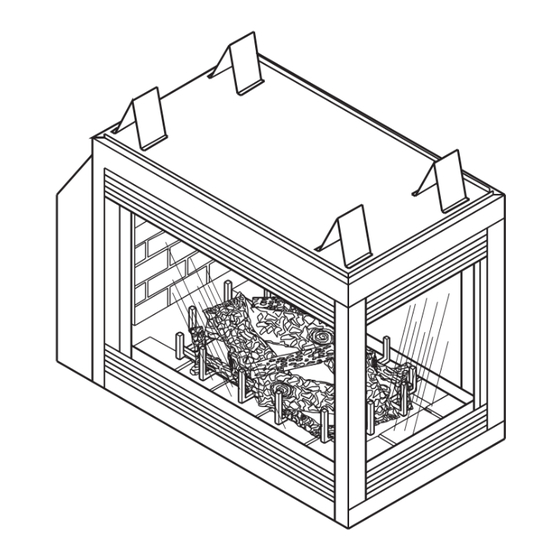
Peninsula Model
Shown
f i r e - p a r t s . c o m
DVF32TMHST-A, DVF32TMHST-A1 AND DVF32TMHST-A2
WARNING: If the information in this manual is not
followed exactly, a fire or explosion may result causing
property damage, personal injury or loss of life.
— Do not store or use gasoline or other flammable
vapors and liquids in the vicinity of this or any other
appliance.
— WHAT TO DO IF YOU SMELL GAS
• Do not try to light any appliance.
• Do not touch any electrical switch; do not use any
phone in your building.
• Immediately call your gas supplier from a neighbor's
phone. Follow the gas supplier's instructions.
• If you cannot reach your gas supplier, call the fire
department.
— Installation and service must be performed by a quali-
fied installer, service agency or the gas supplier.
INSTALLER: Leave this manual with the appliance
CONSUMER: Retain this manual for future reference.
DIRECT-VENT FIREPLACE
PENINSULA MODELS DVF32TMHPN-A
SEE-THRU MODELS
For more information, visit www.fmiproducts.com
PFS
®
US
Advertisement
Table of Contents

Subscribe to Our Youtube Channel
Related Manuals for Vexar DVF32TMHPN-A


Summary of Contents for Vexar DVF32TMHPN-A
- Page 1 ® Peninsula Model Shown f i r e - p a r t s . c o m PENINSULA MODELS DVF32TMHPN-A SEE-THRU MODELS DVF32TMHST-A, DVF32TMHST-A1 AND DVF32TMHST-A2 WARNING: If the information in this manual is not followed exactly, a fire or explosion may result causing property damage, personal injury or loss of life.
-
Page 2: Table Of Contents
This fireplace is manufactured for Stylecrest Inc. under the Vexar brand name by FMI PRODUCTS, LLC. This fireplace may be installed as an OEM installation in a manufactured (mobile) home and must be installed... -
Page 3: Introduction
A) Modification to the fireplace, components, MHST-A2 (with fan and safety switch) and doors, blower, fans or vent system. DVF32TMHPN-A (with fan) are heat circulat- B) Use of any component part not manu- ing gravity direct vent fireplaces with sealed factured or approved byStyle Crest, Inc. -
Page 4: Safety
SELECTING LOCATION Continued • Never obstruct openings of the appliance or • Do not use this appliance if any part has flow of ventilation air. Keep control compart- been under water. Immediately contact a ments accessible. local service technician to examine the appliance and to replace any part(s) of the •... - Page 5 SAFETY Continued This fireplace reaches high temperatures. Keep children and adults away from hot surface to avoid burns or clothing ignition. Fireplace will remain hot for a time after shutdown. Allow surface to cool before touching. f i r e - p a r t s . c o m Carefully supervise young children when they are in the room with fireplace.
-
Page 6: Dimensions
DIMENSIONS BACK VIEW TOP VIEW (Left Side) (Back) " 24" " (Front) "ø "ø " " (Right Side) " " 3" 3" 1" " RIGHT SIDE FRONT VIEW " 30" (Opening) " 32" " " (Opening) (Opening) f i r e - p a r t s . c o m 25"... -
Page 7: Pre-Installation Preparation
PRE-INSTALLATION PREPARATION LOCATION AND SPACE CLEARANCES REQUIREMENTS Minimum clearances to combustibles for fireplace are as follows: Determine the safest and most efficient location for your Style Crest, Inc. direct-vent Back and sides of surround 0" fireplace. Make sure that rafters and wall Vent Surfaces (side and bottom) 1"... - Page 8 PRE-INSTALLATION PREPARATION Continued FRAMING Woodwork, such as wood trims, mantels and other combustible materials should not be Once final location has been determined, placed within 7" of the opening of fireplace observing clearances for vent termination, (see Figure 6). you may construct framing using dimensions Combustible material above projecting more shown in Figures 7 thru 13 depending on your than 1...
- Page 9 PRE-INSTALLATION PREPARATION Continued The gas supply line may be connected through side framing or alternately through lower sub- flooring or a platform base if provided (see Figures 10 and 11). Depending on installation, refer to appropriate illustrations. Figure 11 - Alternate Gas Supply "...
-
Page 10: Requirements For The Commonwealth Of Massachusetts
REQUIREMENTS FOR THE COMMONWEALTH OF MASSACHUSETTS INSPECTION For all side wall horizontally vented gas fueled equipment installed in every dwelling, building or The state or local gas inspector of the side structure used in whole or in part for residential wall horizontally vented gas fueled equipment purposes, including those owned or operated by shall not approve the installation unless, upon... -
Page 11: General Venting
GENERAL VENTING These models are approved for use with • If using a venting configuration of only Style Crest, Inc. Series, rigid type direct vent horizontal venting with no vertical run, a pipe as supplied by Style Crest, Inc. or with 1/4"... - Page 12 GENERAL VENTING Continued Fixed Openable Fixed Closed Closed Openable TERMINATION CAP GAS METER RESTRICTED AREA AIR SUPPLY INLET (TERMINATION PROHIBITED) A = clearance above grade, veranda, porch, deck, or I = clearance to service regulator vent outlet [*72" (182.9 cm) minimum] balcony [*12"...
-
Page 13: Venting Installation
VENTING INSTALLATION WARNING: Read all instruc- WARNING: This gas fireplace tions completely and thoroughly and vent assembly must be before attempting installation. vented directly to the outside. The Failure to do so could result in venting system must NEVER be serious injury, property damage attached to a chimney serving a or loss of life. - Page 14 VENTING INSTALLATION Continued Note: You may use two 45° elbows in place of WARNING: Do not recess a 90° elbow. You must follow rise to run ratios vent terminal into a wall or sid- when using 45° elbows. For two-story applications, firestops are ing.
- Page 15 VENTING INSTALLATION Continued 2. Rigid vent pipes and fittings have special 4. Three types of vent caps are available twist-lock connections. Assemble desired for horizontal terminations. Two square combination of pipe and elbows to appli- terminals are available; one for rigid pipe ance adaptor with pipe seams oriented applications and one for flex pipe ap- towards wall or floor.
- Page 16 VENTING INSTALLATION Continued 6. Make final connection to vent terminal. WARNING: Do not recess Flush or recessed with short vent sys- tem: Vent system may be pre-sized. Check vent termination in to any wall. for final fit and slide unit into framing with This will cause a fire hazard.
-
Page 17: Vertical Termination
VENTING INSTALLATION Continued Horizontal Termination Configurations Figures 22 and 23 show different configura- tions for venting with horizontal termination. 45° Starter Each figure includes a chart with vertical Elbow minimum/maximum and horizontal maximum dimensions which must be met. All horizon- tal terminations require 1/4"... - Page 18 VENTING INSTALLATION Continued Note: Pay special attention to these instal- Flat Ceiling Installation lation instructions for required clearances 1. Cut a 11 " square hole in the ceiling us- (air space) to combustibles when passing ing locating hole as a center point. Open- ing should be framed to 11 "...
- Page 19 VENTING INSTALLATION Continued 4. Connect a section of pipe and extend Cathedral Ceiling Installation up through hole. If an offset is needed to 1. Remove shingles or other roof covering as avoid obstructions, you must support vent necessary to cut rectangular hole for sup- pipe every 3 feet.
- Page 20 VENTING INSTALLATION Continued Vertical Termination Configurations Any offset pitch of 45° or less must be Figures 29 through 32 show four different considered horizontal and sized within the configurations for vertical termination. These maximum allowable lengths listed in the fol- minimum vertical rises are based on horizon- lowing examples.
- Page 21 VENTING INSTALLATION Continued HIGH ALTITUDE INSTALLATION Your Style Crest, Inc. direct-vent fireplace has been tested and approved for elevations from 0-2,000 feet (USA). When installing a non-high altitude fireplace at an elevation above 2,000 feet (USA), you may need to decrease the input rating by changing the existing burner orifice to a smaller size.
- Page 22 VENTING INSTALLATION Continued PARTS LIST FOR VENTING KITS AND Number Description COMPONENTS PA58-712 Adjustable 7"-12" Section Double Wall Pipe, Galvanized Pipe & Vent Kits FPA58-6 6" Dura Vent Collar to FMI Pipe Number Description Adaptor VKR-58 R o o f Ve n t K i t , G a l v a n i z e d E58-45 45°...
-
Page 23: Fireplace Installation
FIREPLACE INSTALLATION WALL SWITCH INSTALLATION Glass The DVF32TMHPN/TMHST models use a self generated millivolt current that allows you to Locating activate the gas control valve directly without Holes the use of normal household electricity (see Figure 34). Both versions are supplied with Recommended a wall switch kit for ready connection and Blower Speed... - Page 24 FIREPLACE INSTALLATION Continued OPTIONAL WIRELESS HAND-HELD GAS LINE HOOK-UP REMOTE CONTROL INSTALLATION WARNING: Before you pro- Note: If using an optional wireless hand- ceed, make sure your gas supply held remote control, wall switch is no longer is OFF. operational. INSTALLING OPTIONAL WIRELESS WARNING: Gas line hookup HAND-HELD REMOTE CONTROL...
- Page 25 FIREPLACE INSTALLATION Continued CAUTION: Do not kink flex- WARNING: All gas piping and ible gas line. connections must be tested for leaks after the installation is completed. After ensuring that the gas valve is CAUTION: Compounds used open, apply a soap and water solution on threaded joints of gas piping to all connections and joints.
- Page 26 FIREPLACE INSTALLATION Continued INSTALLING LOG SET WARNING: Improper installa- Before proceeding, make sure gas control tion, adjustment, alteration, ser- valve is in the OFF position. Logs have been vice, or maintenance can cause shrink wrapped on a cardboard backing injury or property damage. Refer to prevent breakage during shipping.
-
Page 27: Pilot/Electrode Assembly Adjustment
FIREPLACE INSTALLATION Continued DECORATIVE FACING Left Any noncombustible material may be used for facing (glass, tile, brick, etc.) as long as the proper clearances are observed (see Clearances, page 7). IMPORTANT: Louvered openings must not be obstructed, and upper and lower panels must remain removable for servicing. -
Page 28: Burner Flame Adjustment
BURNER FLAME ADJUSTMENT BURNER REMOVAL The air shutter, located at the base of the main burner (see Figure 50), has been fac- CAUTION: Before proceeding tory preset to the proper air-to-gas ratio which results in an even, clean burning flame across to open glass door or handle logs, the burner (see Figure 51). -
Page 29: Operating Guidelines And Maintenance
OPERATING GUIDELINES AND MAINTENANCE When lit for the first time, appliance may emit WARNING: Have a qualified a slight odor for about 16 - 24 hours. This is normal and is due to the “curing” of logs and agency periodically inspect the “burn-in”... -
Page 30: Operation
OPERATING GUIDELINES AND MAINTENANCE Continued 3. If replacement is necessary, entire assem- Mount new frame at hinge with 5 new bly (frame and glass) must be replaced. screws. Close and latch door. This will If glass is broken, wear gloves and tape seat gasket. -
Page 31: Specifications
OPERATION Continued LIGHTING 12. Close lower louver panel. INSTRUCTIONS 13. To leave pilot lit and shut off burners only, turn control knob clockwise to the 1. STOP! Read the safety information, PILOT position or set selector switch in page 30. the OFF position. -
Page 32: Troubleshooting
TROUBLESHOOTING WARNING: Turn off heater, disconnect power if applicable and let cool before servicing. Only a qualified service person should service and repair heater. CAUTION: Never use a wire, needle, or similar object to clean pilot. This can damage pilot unit. Note: The two most common causes of malfunctioning gas appliances are loose wiring con- nections and construction debris clogging pilot and/or control valve filter. -
Page 33: Wiring Diagrams
TROUBLESHOOTING Continued OBSERVED PROBLEM POSSIBLE CAUSE REMEDY When ignitor button is pressed, 1. Defective ignitor 1. Replace ignitor if wire is there is no spark at pilot properly connected and you have no spark 2. Defective pilot or misaligned 2. Using a match, light pilot. If pi- electrode at pilot lot lights turn off pilot and push piezo again. -
Page 34: Service Hints
SERVICE HINTS REPLACEMENT PARTS When Gas Pressure Is Too Low Note: Use only original replacement parts. • pilot will not stay lit This will protect your warranty coverage for parts replaced under warranty. • burner will have delayed ignition Contact authorized dealers of this product. If •... - Page 35 PARTS AND ACCESSORIES Continued END LOUVER KIT (Peninsula Only) Black - 01645 LOUVER KIT LOG SET - 27237 Log Piece A - 27238 Black - 01627 Log Piece B - 27239 Log Piece C - 27242 Log Piece D - 27240 Log Piece E - 27241 PIEZO IGNITOR - 14261 Front (Bottom)
-
Page 36: Limited Two Year Warranty
This warranty does not cover products used in non-residential applications. 6. This warranty gives you specific legal rights and you may also have other rights that vary from state to state. This fireplace is manufactured for Style Crest Inc. under the VEXAR brand name by: FMI PRODUCTS, LLC 2701 S.
Need help?
Do you have a question about the DVF32TMHPN-A and is the answer not in the manual?
Questions and answers