Advertisement
Table of Contents
Wood burning Fireplace
oWner'S operaTion and
inSTallaTion Manual
PFS
®
C
US
ICBO #ER-3507
Model c36MW
SAVE THIS BOOK
This book is valuable. In addition to instructing you
on how to install and maintain your appliance, it also
contains information that will enable you to obtain re-
placement parts or accessory items when needed. Keep
it with your other important papers.
This fireplace is approved for use as a wood burning fire-
place or for use with a vented gas log approved to ANS
Z21.60 or Z21.84 standards or for use with a vent-free gas
log heater approved to ANS Z21.11.2 standard. A An ap-
proved hood must be installed when using a vent-free log
heater (see Accessories, page 18).
This firebox meets the construction and safety stan-
dards of H.U.D. for application in mobile homes when
installed according to these instructions.
FOR CANADA: The authority having jurisdiction (such
as the municipal building department, fire department,
etc.) should be contacted before installation to deter-
mine the need to obtain a permit.
INSTALLER: Leave this manual with the appliance.
CONSUMER: Retain this manual for future reference.
For more information, visit www.fmiproducts.com
Advertisement
Table of Contents

Subscribe to Our Youtube Channel
Related Manuals for Vexar C36MW


Summary of Contents for Vexar C36MW
- Page 1 Manual ® ICBO #ER-3507 Model c36MW SAVE THIS BOOK This book is valuable. In addition to instructing you on how to install and maintain your appliance, it also contains information that will enable you to obtain re- placement parts or accessory items when needed.
-
Page 2: Table Of Contents
This wood burning fireplace complies with UL127- CAN/ULC-S610-M87 standard as a FACTORY BUILT APPLIANCE. Table oF conTenTS Safety ..............2 Operation and Maintenance ......14 Specifications ............3 Technical Service..........15 Fireplace Installation..........4 Parts ..............16 Venting Installation ..........7 Replacement Parts ..........18 Optional Gas Line Installation......13 Accessories ............18 SaFeTy • The Style Crest, Inc. warranty will be voided WARNING: Improper instal- by and Style Crest, Inc. disclaims any re- lation, adjustment, alteration,... -
Page 3: Specifications
SpeciFicaTionS 1" AIRSPACE TO COMBUSTIBLE MATERIAL NO COMBUSTIBLE MATERIAL ON FACE 0" TO TOP SPACERS AIR KIT GAS LINE KNOCK OUT KNOCK OUT COMBUSTIBLE WALL BOARD 0.75" AIR SPACE BACK AND 12.875" SIDES 8.125" 9.625" NOT LESS THAN 14" TO 10.188"... -
Page 4: Fireplace Installation
Fireplace inSTallaTion SELECTING LOCATION 3. Set fireplace directly in front of this open- ing and slide unit back until nailing flanges To determine safest and most efficient location touch side framing. for fireplace, you must take into consideration 4. Check level of fireplace and shim with the following guidelines: sheet metal if necessary. 1. Location must allow for proper clearances 5. Before securing fireplace to prepared (see Figures 1 and 2). framing, ember protector must be placed 2. Consider a location where fireplace will between hearth extension (not included) not be affected by drafts, air conditioning and under bottom front edge of fireplace ducts, windows or doors. -
Page 5: Hearth Extension
Fireplace inSTallaTion Continued HEARTH ExTENSION Seal Gap Fireplace Front A hearth extension projecting a minimum of 16" in front of and a minimum of 8" beyond each side of fireplace opening is required to Ember Protector protect combustible floor construction in front of fireplace. Fabricate a hearth extension using a material which meets the following specifications: a layer of noncombustible, inorganic material having a thermal conductiv- Do Not Block Louver Hearth ity of K=0.84 BTU IN/FT, HR. F (or less) at 1" Extension thick. For example, if material selected has a K factor of 0.25, such as glass fiber, the Fireplace Front Seal Gap... - Page 6 Fireplace inSTallaTion Continued MANTELS FAN/BLOWER KIT ASSEMBLY A mantel may be installed if desired (see Fan or blower kit is optional with this fireplace Figure 4). Woodwork such as wood trims, (for circulating models only). Use of blowers mantels or any other combustible material or fans other than model BK3 voids warranty. projecting from front face must not be placed Fan is operated by pressing rocker switch within 9" of fireplace opening (and within 9" (see Figure 6) in lower right hand corner of of top louver opening). Combustible materi- fireplace face. Blower is operated by turning...
-
Page 7: Venting Installation
VenTing inSTallaTion OPTIONAL OUTSIDE AIR KIT WARNING: The opening in (MODEL AK4/AK4F) collar around chimney at top of Installation of outside air kit should be per- fireplace must not be obstructed. formed during rough framing of fireplace due Never use blown insulation to fill to the nature of it's location. Outside combus- tion air is accessed through a vented crawl chimney enclosure. - Page 8 VenTing inSTallaTion Continued ASSEMBLY AND INSTALLATION OF installing double wall snap-lock chimney to- gether, it is important to assure joint between DOUBLE WALL CHIMNEY SYSTEM chimney sections is locked. Check by pulling Each double wall chimney section consists chimney upward after locking. Chimney will of a galvanized outer pipe, a stainless steel not come apart if properly locked. It is not inner flue pipe and a wire spacer. Pipe sec- necessary to add screws to keep chimney to- tions must be assembled independently as gether (exception - see Figure 11, page 9). chimney is installed. When connecting chim- ney directly to fireplace, inner flue pipe sec- USING ELBOW OFFSETS (30E-8DM) tion must be installed first with lanced side 1. To achieve desired offset, you may install up. Outer pipe section can then be installed combinations of 12", 18", 24", 36" and over flue pipe section with hemmed end up.
- Page 9 VenTing inSTallaTion Continued See Detail A Ceiling Support Pipe 12S-8DM 2" Min. See Detail B Straps Straps Straps Straps Detail A Detail B Return Elbow Angle Firestop Figure 10 - Ceiling Support Pipe 12S-8DM OFFSET RISE CHIMNEY LENGTH 48" 36" 24" 18" 12" " " ELBOW SET ONLY " " " " 15"...
- Page 10 VenTing inSTallaTion Continued FIRESTOP SPACERS (3600FS-8DM-1) 4. Remove shingles around opening mea- sured. Cut out this section. Firestop spacers are required at each point 5. Add next sections of pipe until end where chimney penetrates a floor space. penetrates roof line. Check to see that Their purpose is to establish and maintain proper clearances are maintained. Extend required clearance between chimney and chimney by adding sections of double wall...
-
Page 11: Chase Installations
VenTing inSTallaTion Continued Overlap Terminations with 16" slip pipe sections are Storm Collar Shingles Top available. RTT-8DM and RTTL-8DM are Flashing and Sides Only approved for flashing installations. When Cone needed, these adjustable terminations may Nail Only be used in combination with pipe assembly Outer to achieve correct chimney height. Perimeter Note: In the rare instance there is a problem of Flashing with side driven rain or wind or chimney is not drafting properly, an ADS-8DM (Anti-Draft Shield) can be used with round terminations. -
Page 12: Foot Rule
VenTing inSTallaTion Continued 10 FOOT RULE FINISHING FIREPLACE All flue gas outlet chimney terminations must Combustible materials, such as wallboard, extend a minimum of 3 feet in height above gypsum board, sheet rock, drywall, plywood, highest point where it passes through roof and etc., may make direct contact with sides and must be at least 2 feet above highest point of top around fireplace face. It is important that the roof that is within a horizontal distance of combustible materials do not overlap face 10 feet (see Figure 19). itself. Brick, glass, tile or other noncombustible materials may overlap front face provided Level of they do not obstruct essential openings such Flue Gas as louvered slots. When overlapping with Outlet a noncombustible facing material, use only noncombustible mortar or adhesive. -
Page 13: Optional Gas Line Installation
opTional gaS line inSTallaTion Gas line hook up should be done by your Note: An approved hood must be installed supplier or a qualified service person. when using an unvented gas log set (see Accessories on page 18). Note: Before you proceed, make sure your gas supply is turned off. -
Page 14: Operation And Maintenance
opTional gaS line inSTallaTion Continued WARNING: If the fireplace WARNING: When using has been used for wood burn- a decorative vented gas log, ing, firebox and chimney must damper must be removed or be cleaned of soot, creosote and permanently locked in fully open ashes be a qualified chimney position and glass doors must cleaner. -
Page 15: Technical Service
operaTion and MainTenance Continued DAMPER HANDLE OPERATION Damper Damper handle, which opens and closes Handle damper blade, is located inside firebox at center towards back wall (see Figure 24). Pushing handle back into keyway slot will free damper blade to automatically open. To close, push handle back into keyhole slot then pull down and forward to lock it in place (see Figure 25). -
Page 16: Parts
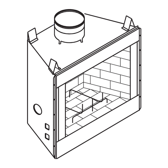
WOOD BURNING FIREPLACE MODEL C36MW www.fmiproducts.com 108918-01K... - Page 17 WOOD BURNING FIREPLACE MODEL C36MW This list contains replaceable parts used in your fireplace. NO. PART NO. DESCRIPTION QTY. Insulation Pan Air Separator Firebox Top 111431-01 Air Deflector Fireplace Top Firebox Wrapper Outer Wrapper/Insulation Assembly Firebox Floor Wrapper Bottom Front Face Weldment 106971-01 Left Side Brick Liner 12 106969-01 Rear Brick Liner 13 106970-01 Right Side Brick Liner 14 106972-01 Bottom Brick Liner 15 106973-01 Front Bottom Brick Liner 16 21198 Blower Access Plate...
-
Page 18: Replacement Parts
acceSSorieS DOUBLE WALL PIPE 12-8DM 18-8DM 24-8DM 36-8DM 48-8DM BI-FOLD GLASS DOOR (Black included on unit) BDB36B - Brushed Brass BDB36P - Platinum ROOF FLASHING 0 TO 6/12 PITCH - V6F-8DM 6/12 TO 12/12 PITCH - V12F-8DM STORM COLLAR SC1-1 For RT-8DM and RTL-8DM ANTI-DRAFT SHIELD SC2-1 For RTT-8DM and RTTL-8DM (Round Top Termination Only) - Page 19 acceSSorieS Continued OUTSIDE AIR KIT FOR FLOOR INSTALLATION ROUND TOP TERMINATIONS AK4F RT-8DM, RTL-8DM ROUND TOP TERMINATIONS WITH SLIP SECTION RTT-8DM, RTTL-8DM SQUARE CHASE-TOP TERMINATION ET-8DM, ET-8DM SQUARE TOP TERMINATION WITH OUTSIDE AIR KIT FOR SIDE WALL SLIP SECTION INSTALLATION - AK4 ETL-8DM, ETL-8DM MW8K MW9K...
- Page 20 This fireplace is manufactured for Style Crest, Inc. under the VEXAR brand name by: FMI PRODUCTS, LLC 2701 S. Habor Blvd. Santa Ana, CA 92704 www.fmiproducts.com 108918-01 Rev. K 09/09...
Need help?
Do you have a question about the C36MW and is the answer not in the manual?
Questions and answers