Fujitsu AOU36RLXFZ1 Installation Manual
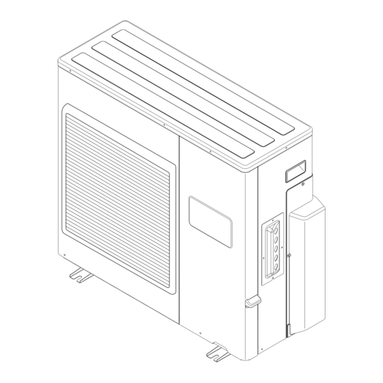
Outdoor unit
Hide thumbs
Also See for AOU36RLXFZ1:
- Service manual (61 pages) ,
- Design & technical manual (319 pages)

Related Manuals for Fujitsu AOU36RLXFZ1


Summary of Contents for Fujitsu AOU36RLXFZ1
-
Page 1: Installation Manual
AIR CONDITIONER OUTDOOR UNIT INSTALLATION MANUAL For authorized personnel only. MANUEL D'INSTALLATION Pour le personnel agréé uniquement. MANUAL DE INSTALACIÓN Solo para personal autorizado. PART No. 9374747153 En-1... -
Page 2: Table Of Contents
AIR CONDITIONER SPECIAL PRECAUTIONS INSTALLATION MANUAL When Wiring ELECTRICAL SHOCK CAN CAUSE SEVERE PERSONAL INJURY OR DEATH. ONLY PART No. 9374747153 A QUALIFIED, EXPERIENCED ELECTRICIAN SHOULD ATTEMPT TO WIRE THIS Outdoor Unit SYSTEM. • Do not supply power to the unit until all wiring and tubing are completed or reconnected Contents and checked. -
Page 3: About The Product
• Be careful not to scratch the air conditioner when handling it. • All Fujitsu General products are manufactured to metric units and tolerances. Do not throw away the connecting parts until the installation has been complete. - Page 4 2. 4. 1. Connectable indoor unit capacity type CAUTION The total capacity of the indoor units connected must be between 27,000 and 39,000 BTU. Connection patterns are restricted. Normal operatio n is not guaranteed if connected pattern in the combination not listed below. The product may be damaged. Surely connect in accordance with the combination in the following connection pattern.
- Page 5 Indoor unit connection pattern OUTDOOR UNIT:18 type Indoor unit Power source Power supply cable UNIT B 208/230 V ~ 60 Hz 7-12 7,000 7,000 – 9,000 7,000 – Connection cable 12,000 7,000 – 15,000 7,000 – 18,000 7,000 – 9,000 9,000 –...
-
Page 6: Installation Work
2. 4. 6. Limitation of refrigerant piping length 3. INSTALLATION WORK CAUTION Please obtain the approval of the customer when selecting the location of installation and installing the unit. The total maximum pipe lengths and height difference of this product are shown in the table. -
Page 7: Drain Installation
3. 2. Drain installation 3. 3. Installation dimensions 36 type only CAUTION CAUTION Install the unit where it will not be tilted by more than 3˚. However, do not install the unit with it tilted towards the side containing the compressor. Perform drain work in accordance with this Manual, and ensure that the drain water is properly drained. -
Page 8: Transportation Of The Unit
When an obstruction is present also in the upward area 3. 5. Installation of the unit • Install 4 anchor bolts at the locations indicated with arrows in the figure. • When there are obstacles at the back, side(s), and top •... -
Page 9: Pipe Installation
(1) Detach the caps and plugs from the pipes. 4. PIPE INSTALLATION - 1 (2) Center the pipe against the port on the outdoor unit, and then turn the flare nut by hand. 4. 1. Flare connection (pipe connection) CAUTION To prevent gas leakage, coat the flare Do not use mineral oil on a flared part. -
Page 10: Electrical Wiring
4. 1. 3. How to use adapter (Connection ports of outdoor unit) 5. 1. Electrical requirement • When using the ADAPTER, be careful not to overtighten the nut, or the smaller pipe may be damaged. CAUTION • Apply a coat of refrigeration oil to the threaded connection port of the outdoor unit where the flare nut comes in. -
Page 11: Connection Diagrams
18 type 5. 3. Connection diagrams INDOOR UNIT OUTDOOR UNIT 36 type INDOOR UNIT A (Inter-unit) TERMINAL INDOOR UNIT OUTDOOR UNIT Power lines TERMINAL UNIT A 208/230 V INDOOR UNIT A (Inter-unit) TERMINAL 208/230 V Power lines TERMINAL UNIT A 208/230 V 208/230 V 208/230 V... - Page 12 18 type Look nut Conduit plate Power supply cable Knockout hole Power supply cable UNIT B connection cable Connection cable UNIT A connection cable 36 type (5) Be sure to seal the holes when applying the putty. Place the cables side by side. (Do not overlap the cables.) (6) Put the service cover and valve cover back after completion of the work.
-
Page 13: Pipe Installation
(12) Remove the blank caps, and fully open the spindles of the 2-way and 3-way 6. PIPE INSTALLATION - 2 valves with a hexagon wrench. [torque : 4.4 to 5.2 lbf·ft. (6 to 7 N·m)]. 6. 1. Vacuum (13) Tighten the blank caps and charging port cap of the 2-way valve and 3-way valve to the specified torque. -
Page 14: Additional Charging
6. 2. Additional charging 9. TEST RUN Refrigerant suitable for a total piping length of 164 ft is charged in the outdoor unit at the The test run method may be different for each indoor unit that is connected. Refer to the installation instruction sheet included with each indoor unit. -
Page 15: Confirming The Operation Of Indoor Unit
Hole LED is on the reverse side of the board. 9. 2. Confirming the operation of indoor unit Run the unit in a normal way, and confirm its operation. (Please end the test run first before confirmation) (1) Cold air (or warm air) must be discharged from the indoor unit. (2) The indoor unit operates normally when air direction or air volume adjustment button is pressed.
Need help?
Do you have a question about the AOU36RLXFZ1 and is the answer not in the manual?
Questions and answers