Sign In
Upload
Download
Table of Contents
Contents
Add to my manuals
Delete from my manuals
Share
URL of this page:
HTML Link:
Bookmark this page
Add
Manual will be automatically added to "My Manuals"
Print this page
×
Bookmark added
×
Added to my manuals
Manuals
Brands
biodex Manuals
Treadmill
950-275
Installation & operation manual
biodex 950-275 Installation & Operation Manual
Rehabilitation treadmill
Hide thumbs
1
2
Table Of Contents
3
4
5
6
7
8
9
10
11
12
13
14
15
16
17
18
19
20
21
22
23
24
25
26
27
28
29
30
31
32
33
34
35
36
37
38
39
40
41
42
43
44
page
of
44
Go
/
44
Contents
Table of Contents
Troubleshooting
Bookmarks
Table of Contents
Contents
Table of Contents
Introduction
Clinical Considerations
The Numeric Display/Control Panel
Basic Operation of the Rtm 400
Changing Measurement Units
Using the RS-232 Computer Interface Port
Maintenance
Maintenance Procedures
Troubleshooting
System Diagnostics
Optional
Calibration Verification
Replacement
Specifications
Advertisement
Quick Links
1
Basic Operation of the Rtm 400
2
Maintenance
3
Maintenance Procedures
4
Troubleshooting
5
System Diagnostics
6
Replacement
7
Specifications
Download this manual
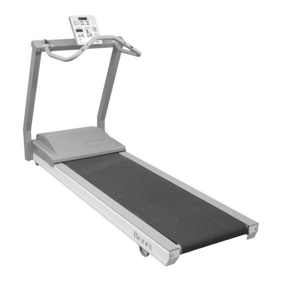
BIODEX RTM 400
REHABILITATION TREADMILL
INSTALLATION/ OPERATION MANUAL
950-275
950-273
950-274
B
IODEX
Biodex Medical Systems, Inc.
20 Ramsay Road, Shirley, New Y ork, 11967-4704, Tel: 800-224-6339 (Int'l 631-924-9000), Fax: 631-924-9338, Email: info@biodex.com, www.biodex.com
FN: 06-172 Rev A 5/09
Table of
Contents
Previous
Page
Next
Page
1
2
3
4
5
Advertisement
Table of Contents
Need help?
Do you have a question about the 950-275 and is the answer not in the manual?
Ask a question
Questions and answers
Related Manuals for biodex 950-275
Treadmill Biodex 950-400 Operation Manual
Gait trainer 3 (67 pages)
Treadmill biodex 950-400 User Manual
Addendum gait trainer software manual (20 pages)
Treadmill biodex rtm 600 Operation Manual
Rehabilitation treadmill (45 pages)
Treadmill biodex 950-387 Application/Operation Manual
Gait trainer 2 (55 pages)
Treadmill biodex GAIT TRAINER 3 Application/Operation Manual
(115 pages)
Treadmill biodex GAIT TRAINER 3 Installation And Assembly Manual
Handrail installation procedure (8 pages)
Treadmill biodex GAIT TRAINERT 3 Software Manual
(12 pages)
This manual is also suitable for:
950-273
Rtm 400
950-274
Table of Contents
Print
Rename the bookmark
Delete bookmark?
Delete from my manuals?
Login
Sign In
OR
Sign in with Facebook
Sign in with Google
Upload manual
Upload from disk
Upload from URL


Need help?
Do you have a question about the 950-275 and is the answer not in the manual?
Questions and answers