Huawei Y300 Maintenance Manual
Hide thumbs
Also See for Y300:
- User manual (161 pages) ,
- Faqs (86 pages) ,
- Quick start manual (29 pages)

Related Manuals for Huawei Y300


Summary of Contents for Huawei Y300
- Page 1 Y300 Maintenance Manual Issue Date 2013-01-24 HUAWEI TECHNOLOGIES CO., LTD.
- Page 2 Notice The purchased products, services and features are stipulated by the contract made between Huawei and the customer. All or part of the products, services and features described in this document may not be within the purchase scope or the usage scope. Unless otherwise specified in the contract, all statements, information, and recommendations in this document are provided "AS IS"...
-
Page 3: About This Document
About This Document Purpose Prepared by Date Reviewed by Date Approved by Date Change History Date Version Revision Reason Changed Description Author Chapter 2012-11-14 V1.0 2013-01-06 V2.0 Issue 1.0 (2013-01-24) Huawei Proprietary and Confidential Copyright © Huawei Technologies Co., Ltd. -
Page 4: Table Of Contents
7 Disassembly Procedure ......................22 8 Assembly Procedure ........................25 9 Principles and Failure Analysis ....................28 9.1 Y300 Conceptual Block Diagram and Introduction ..................28 9.2 Baseband Unit ..............................29 9.2.1 Startup Management Circuit ......................... 29 9.2.2 Charging Management Circuit ......................34 Issue 1.0 (2013-01-24) - Page 5 10 Solder Points on the PCB and BGA Chip................76 11 Functional Tests......................... 86 11.1 Keys ................................86 11.2 MMI Tests ..............................87 11.3 Voice Call Test .............................. 87 Issue 1.0 (2013-01-24) Huawei Proprietary and Confidential Copyright © Huawei Technologies Co., Ltd.
-
Page 6: Product Overview
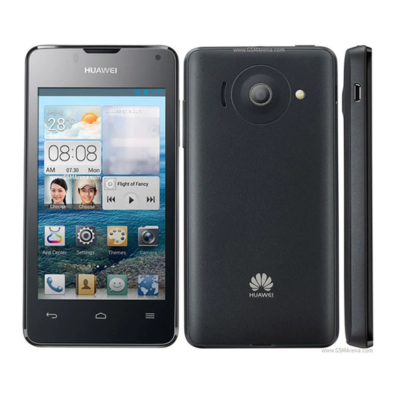
Y300 Maintenance Manual 1 Product Overview Product Overview 1.1 Appearance Figure 1-1 shows the appearance of the Y300. Figure 1-1 Appearance of the Y300 Issue 1.0 (2013-01-24) Huawei Proprietary and Confidential Copyright © Huawei Technologies Co., Ltd. -
Page 7: Specifications
Charger 5 V, 550 mA Flash memory ROM: 4 GB RAM: 512 MB Camera Y300-0000: 5 MP full-frame rear camera Y300-0100 and Y300-0151: 5 MP autofocus rear camera and 0.3 MP full-frame front camera Bluetooth WCN2243 Bluetooth v2.1 Wi-Fi 802.11b/g/n... - Page 8 Headset jack 3.5-mm headset jack Temperature Operating temperature: –10° C to +55° C Storage temperature: –40° C to +70° C Humidity Operating humidity: 5% to 95% RH Issue 1.0 (2013-01-24) Huawei Proprietary and Confidential Copyright © Huawei Technologies Co., Ltd.
-
Page 9: Applicable Scope And Precautions
2.1 Applicable Scope This document provides repair instructions for technicians at service centers authorized by Huawei. Being Huawei proprietary, this document is accessible only for authorized service centers and companies. Although every effort was made to ensure the accuracy of this document, errors may still exist. -
Page 10: Exploded View
Y300 Maintenance Manual 3 Exploded View Exploded View Figure 3-1 shows the exploded view of the Y300. Figure 3-1 Exploded view Table 3-1 lists components in the exploded view. Table 3-1 Components in the exploded view Description Quantity Touch panel Issue 1.0 (2013-01-24) - Page 11 Conductive foam of the rear camera Rear camera Speaker Rear cover assembly Tamper-resistant label GPS antenna Wi-Fi antenna Battery cover Battery Product label Volume key FPC Screws Main antenna SIM card FPC Issue 1.0 (2013-01-24) Huawei Proprietary and Confidential Copyright © Huawei Technologies Co., Ltd.
- Page 12 Quantity BB shielding cover RF shielding cover Front camera (for the Y300-0100 and Y300-0151 only) PM shielding cover The components listed in Table 3-1 are structural parts of the phone, and cannot be used as reference when requesting spare parts.
-
Page 13: Components On The Main Pcb
Y300 Maintenance Manual 4 Components on the Main PCB Components on the Main PCB Issue 1.0 (2013-01-24) Huawei Proprietary and Confidential Copyright © Huawei Technologies Co., Ltd. - Page 14 4 Components on the Main PCB The following component list is for your reference only and subject to changes without notices. The latest component list is available in Huawei's ITEM information system. If you have any question, contact your local technical support center.
- Page 15 Oscillating Motor, SMT, 2.7, 75 A, 14000 rpm, 11 mm*4.4 mm*3.6 32050032 mm, Null, 28ohm 14240646 IO Connector, Micro_B-Female, 5 pin, 1.77 mm Height from PCB Top Side, SMT, Terminal Dedicated Issue 1.0 (2013-01-24) Huawei Proprietary and Confidential Copyright © Huawei Technologies Co., Ltd.
-
Page 16: Software Upgrade
Upgrade the software using the customization package package provided by the operator. Upgrade method Upgrading using Normal upgrade the microSD card Forcible upgrade 5.2 Hardware Connection Figure 5-1 shows the hardware connection. Issue 1.0 (2013-01-24) Huawei Proprietary and Confidential Copyright © Huawei Technologies Co., Ltd. -
Page 17: Upgrade Using The Usb Driver
Step 1 Double-click DriverSetup.exe to display the dialog box shown in Figure 5-2, and click Install to start the installation. Figure 5-2 Installing the USB driver Figure 5-3 shows the installation progress. Issue 1.0 (2013-01-24) Huawei Proprietary and Confidential Copyright © Huawei Technologies Co., Ltd. - Page 18 Step 2 After the installation is completed, click Close, as shown in Figure 5-4. Figure 5-4 Closing the dialog box Step 3 Power on the Y300, connect it to the computer using a USB cable, and click Device Manager to display the Computer Management window. Then, check that the port information is correct, as shown in Figure 5-5.
-
Page 19: Performing A Normal Upgrade
5.3.2 Performing a Normal Upgrade To perform a normal upgrade: Step 1 Power on the Y300, and use a USB cable to connect the Y300 to the computer on which the USB driver and 10KNewMu have been installed. Step 2 Double-click 10KNewMu. - Page 20 Figure 5-6 Select Bin File dialog box Step 4 Click Scan && Download to start the upgrade, as shown in Figure 5-7. Figure 5-7 Starting the upgrade Figure 5-8 shows the upgrade progress. Issue 1.0 (2013-01-24) Huawei Proprietary and Confidential Copyright © Huawei Technologies Co., Ltd.
- Page 21 Y300 Maintenance Manual 5 Software Upgrade Figure 5-8 Upgrade progress If the upgrade is complete, Download Success is displayed, as shown in Figure 5-9. Figure 5-9 Download Success ----End Issue 1.0 (2013-01-24) Huawei Proprietary and Confidential Copyright © Huawei Technologies Co., Ltd.
-
Page 22: Performing A Forcible Upgrade
Step 3 Insert the microSD card into the Y300 and power on. After the home screen is displayed, choose Settings > All > About phone > System update > Update via SD card > Confirm >... -
Page 23: Performing A Forcible Upgrade
Step 2 Create a folder dload in the root directory of the microSD card and copy UPDATA.APP from the main upgrade package to the dload folder. Step 3 With the Y300 powered off, press and hold the power key and the volume up and volume down keys to drive the Y300 to enter forcible upgrade mode. - Page 24 Failed to upgrade the Y300 using the 2. Check that the upgrade method is correct. microSD card. 3. Check that the microSD card functions properly. 4. Perform the upgrade again. Issue 1.0 (2013-01-24) Huawei Proprietary and Confidential Copyright © Huawei Technologies Co., Ltd.
-
Page 25: Repair Tools
Name: heat gun Usage: heats components Name: soldering iron Usage: solders components Name: DC power supply Usage: supplies power Name: soldering fixture Usage: fixes the main PCB Issue 1.0 (2013-01-24) Huawei Proprietary and Confidential Copyright © Huawei Technologies Co., Ltd. - Page 26 Name: lead-free tin solder wire Usage: solders components Name: digital multimeter Usage: measures parameters during maintenance Name: toolkit Usage: assembles and disassembles the Y300 Name: electric screwdriver Usage: fastens and removes screws Issue 1.0 (2013-01-24) Huawei Proprietary and Confidential Copyright © Huawei Technologies Co., Ltd.
-
Page 27: Disassembly Procedure
Y300 Maintenance Manual 7 Disassembly Procedure Disassembly Procedure 2. Start to disassemble the Y300. 1. Wear the ESD wrist strap and ensure that the ESD wrist strap is properly grounded. 3. Remove the battery cover: Pry open the battery 4. Remove the battery. - Page 28 6. Use the disassembly tab to release the clip in the upper right corner. 5. Remove the eight screws on the back cover. 7 Loosen the volume key FPC. 8. Remove the volume key FPC. Issue 1.0 (2013-01-24) Huawei Proprietary and Confidential Copyright © Huawei Technologies Co., Ltd.
- Page 29 9. Release the BTB connector cable of the touch panel, 10. Separate the front cover and main PCB. LCD, and camera. 11. Remove the SIM card FPC. 12. Remove the LCD. 13. Remove the receiver. Issue 1.0 (2013-01-24) Huawei Proprietary and Confidential Copyright © Huawei Technologies Co., Ltd.
-
Page 30: Assembly Procedure
Assembly Procedure 1. Wear the ESD wrist strap and ensure that the ESD 2. Start to assemble the Y300. wrist strap is properly grounded. 3. Assemble components on the front cover, including (1) receiver, (2) power key FPC, and (3) touch panel. - Page 31 8 Assembly Procedure 4. Assemble components on the rear cover, including (1) speaker, (2) GPS antenna, (3) Wi-Fi antenna, and (4) antenna support (and diversity antenna for the Y300-0100 and Y300-0151). 4. Assemble the LCD onto the front cover. 5. Assemble the standby PCB and accessories.
- Page 32 LCD, and attach and fix (2) the volume key FPC onto the main PCB. 7. Attach the rear cover assembly to the front cover. 8. Fasten the screws. Issue 1.0 (2013-01-24) Huawei Proprietary and Confidential Copyright © Huawei Technologies Co., Ltd.
-
Page 33: Principles And Failure Analysis
The Y300 is a UMTS bar-type phone developed by Huawei. It adopts the MSM8225+PM8029 chip solution provided by Qualcomm. The Y300's main PCB consists of the MSM8225, PM8029, and RF components. The main PCB connects to components in several ways, including: ... -
Page 34: Baseband Unit
9 Principles and Failure Analysis An integrated Y300 is consisted of the main PCB, structural components, and a battery. The Y300 supports multiple functions, such as the voice service, short message service (SMS), and microSD card storage, and can save contacts and text messages in the USIM/SIM card or the phone. - Page 35 Figure 9-3 Circuit diagram for startup management (2) Analysis The Y300 adopts the independent power management chip PM8029. The PM8029's startup process is controlled by Qualcomm's codes. When the PM8029 detects that the KPD_PWR_ON level is low, the PM8029 enables the startup process. During the startup...
- Page 36 Startup faults can be divided into the following types: No current: After you connect the Y300 to the DC power supply and press the power key, the DC current ranges from 0 mA to 5 mA. ...
- Page 37 DC current exceeds 300 mA. If the Y300 fails to be powered on, observe the DC current upon startup to identify the fault. Figure 9-5, Figure 9-6, and Figure 9-7 show the fault identification processes upon no current, weak current, and strong current.
- Page 38 Figure 9-6 Fault identification process upon weak current The Y300 fails to be powered on. Install a simulated battery on the Y300, connect the Y300 to the maintenance power, press the power key, and observe the current. The current is weak.
-
Page 39: Charging Management Circuit
Figure 9-7 Fault identification process upon strong current The Y300 fails to be powered on. Install a simulated battery on the Y300, connect the Y300 to the maintenance power, press the power key, and observe the current. The current is strong. - Page 40 Y300 Maintenance Manual 9 Principles and Failure Analysis Figure 9-8 Circuit diagram for charging management (1) Figure 9-9 Circuit diagram for charging management (2) Issue 1.0 (2013-01-24) Huawei Proprietary and Confidential Copyright © Huawei Technologies Co., Ltd.
- Page 41 A charger is connected to the Y300 but the Y300 does not respond. The Y300 displays the charging icon on the screen but in fact the battery fails to be charged. Handling: Check whether the I/O battery connector is damaged. Troubleshoot the fault according to the process shown in Figure 9-11.
- Page 42 Y300 Maintenance Manual 9 Principles and Failure Analysis Figure 9-11 Troubleshooting process when the Y300 fails to be charged The Y300 fails to be charged after connecting to a charger. Replace the Does the charger charger. operate properly? Is the J901 dry Re-weld the J901.
-
Page 43: Clock Circuit
Figure 9-12 Circuit diagram of the 19.2 MHz clock (1) Figure 9-13 Circuit diagram of the 19.2 MHz clock (2) Figure 9-14 shows the circuit diagram of the 32.768 kHz clock. Issue 1.0 (2013-01-24) Huawei Proprietary and Confidential Copyright © Huawei Technologies Co., Ltd. - Page 44 The 32.768 kHz oscillator delivers signals to the PM8029, which provides signals to the system. Troubleshooting Fault symptom: The Y300 fails to be powered on or frequently breaks down. Checks on the 32.768 kHz oscillator show that the X301 and U3101 have no output or the frequencies are unstable.
-
Page 45: Flash Memory Circuit
19.2 MHz clock output 9.2.4 Flash Memory Circuit Circuit Diagram Figure 9-16, Figure 9-17, Figure 9-18, and Figure 9-28 show the circuit diagrams of the flash memory. Issue 1.0 (2013-01-24) Huawei Proprietary and Confidential Copyright © Huawei Technologies Co., Ltd. - Page 46 Y300 Maintenance Manual 9 Principles and Failure Analysis Figure 9-16 Circuit diagram of the flash memory (1) Figure 9-17 Circuit diagram of the flash memory (2) Issue 1.0 (2013-01-24) Huawei Proprietary and Confidential Copyright © Huawei Technologies Co., Ltd.
- Page 47 Y300 Maintenance Manual 9 Principles and Failure Analysis Figure 9-18 Circuit diagram of the flash memory (3) Issue 1.0 (2013-01-24) Huawei Proprietary and Confidential Copyright © Huawei Technologies Co., Ltd.
- Page 48 Analysis The MSM8225 can access the LPDDR through the high-speed bus EBI1 and the external storage eMMC using a low-speed bus EBI2, as shown in Figure 9-20. Issue 1.0 (2013-01-24) Huawei Proprietary and Confidential Copyright © Huawei Technologies Co., Ltd.
- Page 49 The Y300 incorporates the 4 GB eMMC that uses the eight-bit data cable for transmission. Troubleshooting Fault symptom: The Y300 fails to be powered on, or the startup current is less than 100 mA. Handling: Upgrade or upload the system software, and verify that the VREG_DCDC_2P85 voltage and peripheral components are normal.
-
Page 50: Rf Unit
2.85 V system power supply, None supplying power to the DC/DC chip 9.3 RF Unit Circuit Diagram Figure 9-21 shows the transceiving circuit diagram of the RF unit. Issue 1.0 (2013-01-24) Huawei Proprietary and Confidential Copyright © Huawei Technologies Co., Ltd. - Page 51 1.8 V to 3.0 V. The control signals are provided by the MSM8225. Figure 9-22 shows the circuit diagram of the WCDMA IMT power amplifier (PA). Issue 1.0 (2013-01-24) Huawei Proprietary and Confidential Copyright © Huawei Technologies Co., Ltd.
- Page 52 Figure 9-23 shows the circuit diagram of the WCDMA 900 MHz PA Figure 9-23 Circuit diagram of the WCDMA 900 MHz PA Figure 9-24 shows the circuit diagram of the WCDMA 1900 MHz PA Issue 1.0 (2013-01-24) Huawei Proprietary and Confidential Copyright © Huawei Technologies Co., Ltd.
- Page 53 Figure 9-25 shows the circuit diagram of the GSM quad band PA. Figure 9-25 Circuit diagram of the GSM quad band PA Figure 9-26 shows the circuit diagram of the UMTS IMT RX interstage chain. Issue 1.0 (2013-01-24) Huawei Proprietary and Confidential Copyright © Huawei Technologies Co., Ltd.
- Page 54 Troubleshooting No reception Fault symptom: The Y300 fails to receive signals in the WCDMA 2100/1900/900/850 MHz and the GSM 900/1800 MHz receive channels. Handling: The WCDMA 2100 MHz frequency band is used as an example. Troubleshoot the fault according to the process shown in Figure 9-28.
- Page 55 Y300 Maintenance Manual 9 Principles and Failure Analysis Figure 9-28 Troubleshooting process when the Y300 fails to receive signals The WCDMA 2100 MHz receive channel is faulty. Check U3201 before the RF cable is connected. Are pin 1 and pin 2 of U3201 properly Check the U3201.
- Page 56 No transmission Fault symptom: The Y300 fails to transmit signals in the WCDMA 2100/1900/900/850 MHz and the GSM 900/1800 MHz transmit channels. Handling: The WCDMA 2100 MHz frequency band is used as an example. Ensure that the SIM card and antenna are properly installed and then troubleshoot the fault according to the process shown in Figure 9-29.
- Page 57 Y300 Maintenance Manual 9 Principles and Failure Analysis Figure 9-29 Troubleshooting process when the Y300 fails to transmit signals The WCDMA 2100 MHz transmit channel is faulty. Check U3201 before the RF cable is connected. Are pin 1 and pin 2 of U3201 properly Check the U3201.
- Page 58 I/Q signal of the secondary receive DRX_GPS_I_P None channel DRX_GPS_I_M I/Q signal of the secondary receive None channel PA_ON0 PA for controlling the WCDMA 2100 None MHz frequency band Issue 1.0 (2013-01-24) Huawei Proprietary and Confidential Copyright © Huawei Technologies Co., Ltd.
-
Page 59: Peripheral Circuits
None 9.4 Peripheral Circuits 9.4.1 LCD Circuit Circuit Diagram Figure 9-30, Figure 9-31, and Figure 9-32 show the LCD circuit diagrams. Figure 9-30 LCD circuit diagram (1) Issue 1.0 (2013-01-24) Huawei Proprietary and Confidential Copyright © Huawei Technologies Co., Ltd. - Page 60 Figure 9-32 LCD circuit diagram (3) Analysis The Y300 incorporates a 4.0-inch TFT LCD with a resolution of 800 x 480 pixels. The Y300's LCD uses the Mobile Industry Processor Interface (MIPI), requiring only two pairs of differential signaling cables and one pair of power cables. The LCD interface...
- Page 61 Y300 Maintenance Manual 9 Principles and Failure Analysis Troubleshooting Fault symptom: The Y300 can be powered on, but the LCD displays nothing. Handling: Check the LCD. Troubleshoot the fault according to the process shown in Figure 9-33. Figure 9-33 Troubleshooting process when the LCD displays nothing The LCD displays nothing.
-
Page 62: Motor Circuit
PCB. When the motor is not vibrating, the levels of VPH_PWR and VIB_DRV_N are high. Troubleshooting Fault symptom: The motor does not vibrate. Handling: Troubleshoot the fault according to the process shown in Figure 9-35. Issue 1.0 (2013-01-24) Huawei Proprietary and Confidential Copyright © Huawei Technologies Co., Ltd. - Page 63 Reference Measurement or Symbol Waveform VPH_PWR Main power supply signal, supplying None power to the motor VIB_DRV_N Motor drive signal pin, connected to None the motor's cathode Issue 1.0 (2013-01-24) Huawei Proprietary and Confidential Copyright © Huawei Technologies Co., Ltd.
-
Page 64: Receiver And Speaker
9 Principles and Failure Analysis 9.4.3 Receiver and Speaker Circuit Diagram Speaker Figure 9-36 and Figure 9-37 show the speaker circuit diagrams. Figure 9-36 Speaker circuit diagram (1) Issue 1.0 (2013-01-24) Huawei Proprietary and Confidential Copyright © Huawei Technologies Co., Ltd. - Page 65 Figure 9-38 shows the structure diagram of the MSM8225 for the speaker. Figure 9-38 Structure diagram of the MSM8225 for the speaker Receiver Figure 9-39 and Figure 9-40 show the receiver circuit diagrams. Issue 1.0 (2013-01-24) Huawei Proprietary and Confidential Copyright © Huawei Technologies Co., Ltd.
- Page 66 Y300 Maintenance Manual 9 Principles and Failure Analysis Figure 9-39 Receiver circuit diagram (1) Figure 9-40 Receiver circuit diagram (2) The Y300 provides three kinds of audio output: Receiver output: Signals are delivered by the CPU. Speaker output: Signals are delivered by the PM8029 to the PA and then the speaker.
- Page 67 After a call is established, no voice is received. Are components of left and right receiver channels dry jointed or deflected? Return the Y300 to Huawei for repair. Adjust the headset Is the receiver volume to a proper volume properly set? value.
-
Page 68: Microphone
Figure 9-42 shows the circuit diagram of the primary microphone. Figure 9-42 Circuit diagram of the primary microphone Analysis The primary microphone of the Y300 is powered by the following power supplies: Issue 1.0 (2013-01-24) Huawei Proprietary and Confidential Copyright © Huawei Technologies Co., Ltd. - Page 69 Fault symptom: The Y300 fails to transmit voices. Handling: Troubleshoot the fault according to the process shown in Figure 9-43. Figure 9-43 Troubleshooting process when the Y300 fails to transmit voices After a call is established, no voice is transmitted.
-
Page 70: Headset Circuit
Figure 9-44 shows the headset circuit diagram. Figure 9-44 Headset circuit diagram Analysis The headset is tested using the GPIO_026's HS_DETECT_N after being inserted to the Y300: Before the headset is inserted, HS_DETECT_N is converted to high level by VREG_S3. - Page 71 Is voice heard after the headset is replaced? Is the HS_DETECT voltage changed Replace the after the headset is headset connector. inserted? Return the Y300 to Huawei for repair. Circuit Symbols Signal Symbol Description Reference Measurement or Waveform FM_ANT FM antenna...
-
Page 72: Sim Card Circuit
9.4.6 SIM Card Circuit Circuit Diagram Figure 9-46 and Figure 9-47 shows circuit diagrams of the SIM card. Figure 9-46 Circuit diagram of the SIM card (1) Issue 1.0 (2013-01-24) Huawei Proprietary and Confidential Copyright © Huawei Technologies Co., Ltd. - Page 73 The PM8029 provides input and output signals to control the SIM card port. Troubleshooting Fault symptom: The Y300 fails to detect the USIM/SIM card. Handling: Check that the USIM/SIM card slot is normal. Troubleshoot the fault according to the process shown in Figure 9-48.
- Page 74 Y300 Maintenance Manual 9 Principles and Failure Analysis Figure 9-48 Troubleshooting process when the Y300 fails to detect the USIM/SIM card The Y300 fails to detect the UIM card. Can the Y300 detect the UIM card after the UIM card is replaced?
-
Page 75: I/O Interface Circuit
When a charger is connected to the I/O interface, the charger provides the VCHG charging voltage to charge the battery. When a data cable is connected to the I/O interface, USB_HS_DN and USB_HS_DP are used for communication between the Y300 and computer (to upgrade the Y300's software and read its data). -
Page 76: Microsd Card Port Circuit
Figure 9-50 and Figure 9-51 show the circuit diagrams of the microSD card port. Figure 9-50 Circuit diagram of the microSD card port (1) Figure 9-51 Circuit diagram of the microSD card port (2) Issue 1.0 (2013-01-24) Huawei Proprietary and Confidential Copyright © Huawei Technologies Co., Ltd. -
Page 77: Fm And Bluetooth Circuit
Analysis The U1402 is used to provide the ESD protection and EMI filtering. Troubleshooting Fault symptom: The Y300 fails to detect the microSD card. Handling: Troubleshoot the fault according to the process shown in Figure 9-52. Figure 9-52 The Y300 fails to detect the microSD card. - Page 78 Figure 9-53 Circuit diagram of the FM and Bluetooth Analysis The Y300 integrates Bluetooth and the FM to provide functions, which are implemented by Qualcomm's WCN2243. Bluetooth uses an independent antenna and the FM uses the left- and right-audio channels as the antennas.
- Page 79 Handling: Check the headset channel if the FM module receives signals but no voice is heard. Troubleshoot the fault according to the process shown in Figure 9-54. Issue 1.0 (2013-01-24) Huawei Proprietary and Confidential Copyright © Huawei Technologies Co., Ltd.
- Page 80 Can the FM radio operate properly after the headset connector is re-soldered? Does the FM radio operate properly after software upgrade? Return the Y300 to Huawei for repair. Issue 1.0 (2013-01-24) Huawei Proprietary and Confidential Copyright © Huawei Technologies Co., Ltd.
-
Page 81: Solder Points On The Pcb And Bga Chip
Green (R: 0, G: 255, B: 0) : grounding point Blue (R: 0, G: 0, B: 255) : solder point Upper Part of Main PCB Top View Issue 1.0 (2013-01-24) Huawei Proprietary and Confidential Copyright © Huawei Technologies Co., Ltd. - Page 82 Y300 Maintenance Manual 10 Solder Points on the PCB and BGA Chip Lower Part of the Main PCB Top View Issue 1.0 (2013-01-24) Huawei Proprietary and Confidential Copyright © Huawei Technologies Co., Ltd.
- Page 83 Y300 Maintenance Manual 10 Solder Points on the PCB and BGA Chip Upper Part of Main PCB Bottom View Issue 1.0 (2013-01-24) Huawei Proprietary and Confidential Copyright © Huawei Technologies Co., Ltd.
- Page 84 Y300 Maintenance Manual 10 Solder Points on the PCB and BGA Chip Lower Part of the Main PCB Bottom View Issue 1.0 (2013-01-24) Huawei Proprietary and Confidential Copyright © Huawei Technologies Co., Ltd.
- Page 85 Y300 Maintenance Manual 10 Solder Points on the PCB and BGA Chip U201 Issue 1.0 (2013-01-24) Huawei Proprietary and Confidential Copyright © Huawei Technologies Co., Ltd.
- Page 86 Y300 Maintenance Manual 10 Solder Points on the PCB and BGA Chip U401 Issue 1.0 (2013-01-24) Huawei Proprietary and Confidential Copyright © Huawei Technologies Co., Ltd.
- Page 87 Y300 Maintenance Manual 10 Solder Points on the PCB and BGA Chip U1800 U1002 U1205 Issue 1.0 (2013-01-24) Huawei Proprietary and Confidential Copyright © Huawei Technologies Co., Ltd.
- Page 88 Y300 Maintenance Manual 10 Solder Points on the PCB and BGA Chip U3801 U6000 Issue 1.0 (2013-01-24) Huawei Proprietary and Confidential Copyright © Huawei Technologies Co., Ltd.
- Page 89 Y300 Maintenance Manual 10 Solder Points on the PCB and BGA Chip U1601 U6100 Issue 1.0 (2013-01-24) Huawei Proprietary and Confidential Copyright © Huawei Technologies Co., Ltd.
- Page 90 Y300 Maintenance Manual 10 Solder Points on the PCB and BGA Chip Issue 1.0 (2013-01-24) Huawei Proprietary and Confidential Copyright © Huawei Technologies Co., Ltd.
-
Page 91: Functional Tests
Y300 Maintenance Manual 11 Functional Tests Functional Tests 11.1 Keys Figure 11-1 shows the keys of the Y300. Figure 11-1 Keys of the Y300 Power key/unlock key Headset connector Volume up Volume down Back key Home key Menu key Issue 1.0 (2013-01-24) Huawei Proprietary and Confidential Copyright ©... -
Page 92: Mmi Tests
MMI tests include: Board test: The Y300 directly proceeds to the next test if the board test is successful. microSD card test: The message "No SD card available" is displayed if the microSD card is not inserted. - Page 93 Y300 Maintenance Manual 11 Functional Tests Step 2 Press and hold the power key to power on the Y300. Step 3 Check that the signal strength changes properly on a normal network. Step 4 Place a call to a fixed-line phone and check the voice quality during the call.