Table of Contents
Advertisement
Quick Links
09.07.2016
User's manual
(Firmware v3.21)
Device description
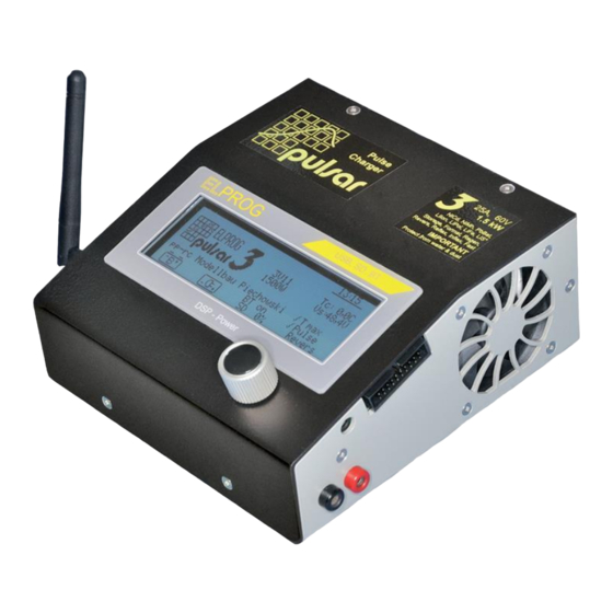
Pulsar 3 is a fast, professional battery charger with an integrated balancer. A newly designed synchronic digital
converter operates with precision and efficiency unmatched by other devices of similar type due to the DSP
(Digital Signal Processor) control. Power, work precision and ease of use were the key focus during the device's
construction. The newest technology, rarely used in model chargers, guarantees an optimal operation of battery
packages. Impulse work in the reflex mode prevents the memory effect and the lazy battery effect in NiXX
batteries as well as lessens the threat of unbalancing in LiXX batteries. The real impulse mode "Fastmod" for Lixx
and Pb batteries can shorten the charge time even by 30-40%. The integrated high-powered balancer equalizes
the packages in a very short time, without unnecessary prolonging the process, thus keeping the singular cells'
voltage perfectly equalized. The multiple algorithms operating simultaneously, which detect the level of the cells'
voltage, as well as the capacity limiter and an integrated temperature indicator, protect the packages from
overloading and damaging. The processes' parameters can be seen on the backlit graphic displayer. The self-
explanatory single Rotary knob, as well as twenty integrated memory banks enable frequently used processes to
be chosen faster, make for easier operation. An SD memory card enables recording the data from all of the
processes, which can then be analyzed via the Pulsar Graph program on a PC or notebook, and helps detect
damage earlier. By analyzing diagrams containing the gathered data, it enables tracing the charging packages'
ageing. Updated data from the process undertaken are sent to a PC through USB or radio data transmission
system (BT), which may in the future send data to cell phones. The charger protects batteries from deep
discharge as well as overloading by controlling the charging batteries' (12, 24 and 48V) parameters, thus
protecting them from damage. A separate AC adapter with a power limiter enables to adapt the work parameters
to a particular charger. Pulsar 3 is protected from reverse connection both at input and output. Pulsar 3, as one
of the few modeling chargers, is equipped with a system that prevents electric arcing when high voltage packs are
plugged in. The device's firmware update also is possible via the Internet.
pulsar 3
1
Advertisement
Table of Contents

Related Manuals for Pulsar 3


Summary of Contents for Pulsar 3
-
Page 1: Device Description
A separate AC adapter with a power limiter enables to adapt the work parameters to a particular charger. Pulsar 3 is protected from reverse connection both at input and output. Pulsar 3, as one of the few modeling chargers, is equipped with a system that prevents electric arcing when high voltage packs are plugged in. -
Page 2: Table Of Contents
23. Prozess set-up – Test 24. Program windows of finished processes 25. Process initialization 26. Process end, reports and alarms Alarms – interrupting the process 27. Updating the software 28. PC software (PulsarGraph) 29. Appendix 1 – Balancer adapter 30. Index pulsar 3... -
Page 3: Technical Specification
Scope of use Pulsar 3 is a charger with an integrated balancer, designed to charge, test and discharge batteries used in all lines of modeling. It may be used to charge lead batteries (car batteries), but the charger is optimised to be used with lead-gel batteries. -
Page 4: Eu - Certificate Of Conformity
EU – Certificate of conformity Pulsar 3 is designed according to the general safety standards – especially home appliance’s standards, such as EN 55014-1:2000 + A1:2001 + A2:2002 as well as EN 55014-2:1997 + A1:2001 (Cat.II) ELPROG ul. Przemysłowa 11 PL 35-105 Rzeszów... -
Page 5: Starting And Operating
Vs = {Vsupply} supply voltage (battery or supply source) Vrev = {Vrevers} max. supplying battery voltage, which – when exceeded – will reduce the charging current with a return (a protection for the supplying battery) Starting and operating Front view 1. Rotary knob pulsar 3... -
Page 6: Connecting The Balancer
Plugging separate pins: 1 = – cell 1; 2 = + cell 1; 3 = + cell 2; 4 = + cell 3; 5 = + cell 4; 6 = + cell 5; 7 = + cell 6; 8 = + cell 7; 9 = + cell 8;... -
Page 7: Batteries (Attributes)
Pulsar 3 is operated using a Rotary knob. The dial can be turned left and right, pressed for a short (up to 1 second) or held for a long (more than 1 second) time. Both pressing and holding is confirmed by an appropriate acoustic signal (if the sound has not been muted in the setup). -
Page 8: Sd, Bt, Rtc" Settings
Attention! First connect the Pulsar 3 to a power source before connecting the battery pack. If the Pulsar 3 should be shut down, first disconnect the battery pack before disconnecting the power source! Never leave a battery pack connected while the charger is offline! -
Page 9: Additional Information Concerning Sd Memory Cards
2011-05-14 – date settings Before plugging the power supply to Pulsar 3, it is important to make sure if the memory card and the BT antenna (optional) are in the charger. After pressing the dial on the “SD, BT, RTC” line in the program window (we go to the program window by holding the dial from any memory window) we are redirected to the „SD, BT, RTC”... -
Page 10: Process Set-Up - Charging Nicd And Nimh Cells
(from M 1 to M 20). Secondly, enter the program window by holding the dial, where the “Mode & Accu” option is selected. Here the battery type and the type of the process that is to be programmed is set. For pulsar 3... -
Page 11: Process Set-Up - Charging Pb Cells
Vc – setting the final charging voltage. If the value differs from the recommended one, an exclamation mark will be displayed (! Vc). For LiPo this value would be 4,00-4,30V/cell; for LiHV 4,05-4,45 V/cell, for LiIo: 3,90- 4,20V/cell; for LiFe: 3,45-3,75V/cell. It is important to mention, that contrary to popular believe 4,20V/cell is not the final safe voltage limit for LiPo cells but only a compromise between current delivery ability and life expectancy. -
Page 12: Process Set-Up - Discharge (All Cell Types)
Vd – final discharge voltage settings. If the set value is other than the recommended settings, an exclamation mark will be displayed (! Vd). For cell types: LiPo 2,80-3,60 V/cell; LiHV 2,8-3,60 V/cell; Li-Ion 2,50-3,30 V/cell; LiFe 2,30-3,10 V/cell NiZn 1,00-1,40 V/cell; NiMH 0,80-1,10V/cell; NiCd 0,60-0,95V/cell;... -
Page 13: Double Processes Set-Up E.g. Charging/Discharging
(parameters)), through discharging and charging. A package prepared by such a function may be stored for a longer time. Pulsar 3 automatically recognizes if the package has to be charged or discharged and after plugging the package, it starts the process required to do this. -
Page 14: Process Set-Up - Format (Only Nicd And Nimh Cells)
…). During formatting a new package, at least 3-4 cycles are recommended. Regen. – a special means of regenerating cells In the used packages, which have lost some of its capacity and have a heightened internal resistance. During formatting with regeneration, at least 2-3 cycles are recommended. ... -
Page 15: Process Set-Up - Balancing Only (Monitor)
The most reliable values are calculated when the voltage of the battery pack is at nominal voltage (eg LiPo 3.7-3.8 V / cell), and discharge in the range of 1 - 2C. In the main display, the internal resistance, as measured by the charging cable is shown. - Page 16 Row of numbers – singular package cells’ numbering starting from the first, plugged into the package’s “minus” cable ↑ 3,53V – voltage of the strongest cell in the package (here cell nr. 9) Δ 0,01V – difference in voltage between the strongest and the weakest cell (10mV in this example).
-
Page 17: Process Initialization
After adjusting the number of cells, if necessary, we can start the process by pressing the Rotary knob. Info: If the Pulsar is connected to an LiXX battery pack without balancer, the double confirmation of cell count is necessary. -
Page 18: Updating The Software
PC software (PulsarGraph v 4.51) The SD memory card added to the Pulsar 3 charger contains the installation version of Pulsar Graph. On the left side of the charger there is a USB socket, through which a direct data flow to the computer is possible during the process (communication is also possible wireless through BT). - Page 19 Below: charts, which appear after pressing „B” (Balance) from the symbol toolbar. In the upper part of the window there are voltage charts for separate cells (only with Am active balancer). It is possible to select and show the charts of the selected cells (see Voltage comparison window – “S” button). pulsar 3...
- Page 20 “B” is enabled) 18. Type of process and the number of cells in the package 19. Current package voltage 20. Current process current 21. Current package temperature 22. Charged or discharged capacity 23. Duration of the process pulsar 3...
- Page 21 (cell 1), delta (the difference between the strongest and the weakest cell) of 0,018V, the weakest cell has 3,578V (cell 3). Voltage of all the cells in the package is shown below. „Data” window, when the balancer is not active.
-
Page 22: Appendix 1 - Balancer Adapter
Pin 1 – cell minus 1 Pin 2 – cell plus 1 / cell minus 2 Pin 3 – cell plus 2 / cell minus 3 ….. Pin 16 – cell plus 15 / cell minus 14 Pin 17 –... - Page 23 Always plug the battery to the interface first and then the adapter to the charger Contact customer service In case of any signs of device malfunction Manufacturer & Service: Distribution & Service ELPROG pp-rc Modellbau Ul. Przemysłowa 11 Paul-Junge-Str. 10 35-105 Rzeszów 25336 Elmshorn Poland Germany www.pp-rc.de WEEE-Reg.-Nr DE77074747 pulsar 3...
-
Page 24: Index
Pb 4 Vrev 5, 12 PC software 19 Vs 5, 7, 11, 13, 15, 17 Personalizing 8 Power 1, 3, 5, 7, 9 Export 8 Process end 17 Δ Process initialization 17 Δ 4, 9, 10, 14, 15, 16, 17...
Need help?
Do you have a question about the 3 and is the answer not in the manual?
Questions and answers