
Related Manuals for Thermaltake VI1000BWS


Summary of Contents for Thermaltake VI1000BWS
- Page 1 All other registered trademarks belong to their respective companies. 2007 Thermaltake Technology Co.,Ltd. All Rights Reserved. www.thermaltake.com...
- Page 2 User's Manual...
-
Page 3: Table Of Contents
Contents Contents Chapter 1. Product Introduction 1.1 Specification Chapter 2 Case Mechanical Operation 2.1 How to open the side panel 2.2 How to install PSU 2.3 5.25" device installation 2.4 3.5" device installation 2.5 HDD installation 2.6 PCI slot usage Chapter 3 Motherboard &... -
Page 4: Chapter1. Product Introduction
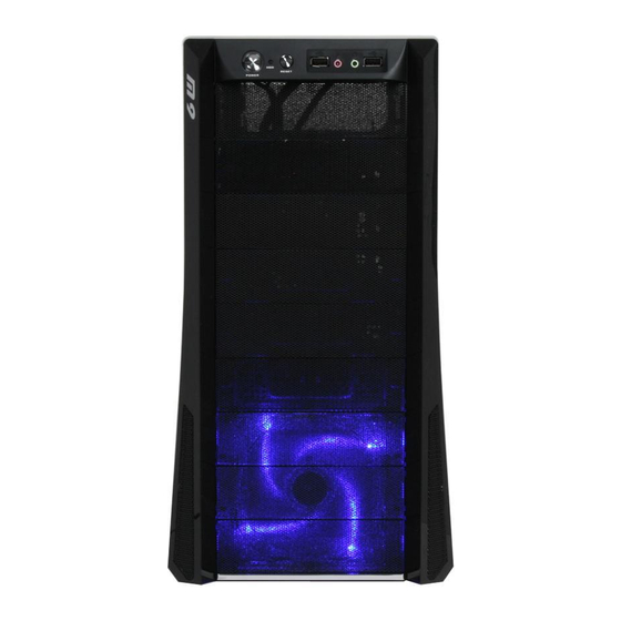
Chapter1. Product Introduction Chapter1. Product Introduction 1.1 Specification Model VI1000BNS VI1000BWS Case Type Middle Tower Transparent Side Side Panel Window Net Weight 6.6 kg 6.4 kg Dimension 440.0 mm x 200.0 mm x 495.0 mm (H*W*D) Front (intake): 120 x 120 x 25 m m,... -
Page 5: Chapter 2 Case Mechanical Operation
Chapter 2 Case Mechanical Operation Chapter 2 Case Mechanical Operation 2.1 How to open the side panel To remove the side panel, please remove upper and bottom thumb screws on the back of the case. Pull the side panel to release it. Important Notice: If the air guide interferes with CPU cooling fan, please remove the CPU air guide as shown. -
Page 6: How To Install Psu
2.2 How to install PSU Then, secure it by screws as shown. Place power supply unit in the right position. 2.3 5.25" device installation Remove the front panel first. Remove the 5.25" drive bay mesh cover. Remove the 5.25" drive bay Turn lock device counter-clockwise to metal cover. -
Page 7: Device Installation
Insert the device into the Find the proper openings. 5.25" drive bay. 5.25" device installation Put back the lock device and turn lock complete. device clockwise to lock. 2.4 3.5" device installation Remove the 5.25" drive bay mesh cover. Take out the 3.5" mesh bay cover from accessory box then install it as shown. - Page 8 Turn lock device counter-clockwise to Pull out the 3.5" rack as shown unlock and remove lock device. Find the proper openings. Screw the 3.5" device by screw driver. Insert the 3.5" device into Find the proper openings. the 5.25" drive bay.
-
Page 9: Hdd Installation
3.5" device installation Put back the lock device and turn lock complete. device clockwise to lock. 2.5 HDD installation Turn lock device counter-clockwise to Pull out the fan cage as shown unlock and remove lock device. Insert the 3.5" HDD into fan cage. Find the proper openings then screw HDD by tigh tening screw to HDD. - Page 10 Insert the fan cage back into Put back the lock device and turn lock the drive bays. device clockwise to lock. Note: Fan Cage is removable and can be installed in different drive bay. Finish HDD installation. Choose another 3 drive bay Put back the lock device and turn at desired location for fan cage lock device clockwise to lock.
-
Page 11: Pci Slot Usage
2.6 PCI slot usage Take off the PCI bracket as shown. Locate Graphic Card to the motherboard through fixing it on the space of PCI bracket. inner side Press the inner side of the clip and pull to the right side to lock the Graphic Card as shown. -
Page 12: Chapter3 Motherboard & Leads Installation
Chapter3 Motherboard & Leads Installation Chapter3 Motherboard & Leads Installation 3.1 Motherboard Installation Each motherboard has different standoff layout. It is highly suggested that you refer to your motherboard's manual when installing motherboard into the Case. The cases are applicable with Standard ATX, Micro ATX motherboards. -
Page 13: Case Led Connections
3.2 Case LED connections On the front of the case, you can find some LEDs and switch leads (POWER SW*1, POWER LED*1, H.D.D. LED*1, RESET SW*1 ). Please consult user manual of your motherboard manufacturer, then connect these leads to the panel header on the motherboard. These leads are usually labeled; if not, please trace them back to the case front to find out their source. -
Page 14: Ear & Mic Connections
3.4 Ear & MIC connections - Please refer to the following illustration of Audio connector and your motherboard user manual. - Please select the motherboard which used AC'97 or HD Audio (Azalia), (be aware of that your audio supports AC'97 or HD Audio (Azalia)) or it will damage your device(s). -
Page 15: Power Supply (Optional)
Furthermore, it has been approved by UL, CUL, TUV, CB, FCC, CE, and BSMI. There are three main products line of Thermaltake PSU which divided into Toughpower, Purepower (include Purepower RX) and TR2 (include TR2 RX) series. Please refer to...
Need help?
Do you have a question about the VI1000BWS and is the answer not in the manual?
Questions and answers