
Subscribe to Our Youtube Channel
Related Manuals for Thermaltake WingMA


Summary of Contents for Thermaltake WingMA
- Page 1 All other registered trademarks belong to their respective companies. 2008.01 2008 Thermaltake Technology Co.,Ltd. All Rights Reserved. www.thermaltake.com...
- Page 2 VI5000BNS User's Manual...
-
Page 3: Table Of Contents
Contents Contents Chapter 1. Product Introduction 1.1 Specification Chapter 2 Case Mechanical Operation 2.1 How to open the side panel 2.2 How to install PSU 2.3 5.25" device installation 2.4 3.5" device installation 2.5 HDD installation 2.6 Front fan installation(optional) 2.7 PCI slot usage Chapter3 Motherboard &... -
Page 4: Chapter1. Product Introduction
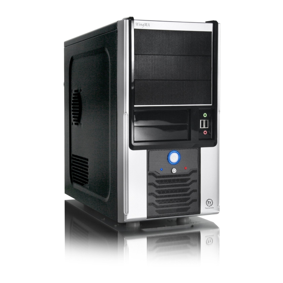
Chapter1. Product Introduction Chapter1. Product Introduction 1.1 Specification Model Model VI5000BNS VI5000BNS Case Type Case Type Middle Tower Middle Tower Net Weight Net Weight 4.7 kg / 10.4 lb Dimension Dimension 360.0 x 190.0 x 413.0 mm 360.0 x 190.0 x 413.0 mm (H*W*D) (H*W*D) (14.2 x 7.5 x 16.3 inch) -
Page 5: Chapter 2 Case Mechanical Operation
Chapter 2 Case Mechanical Operation Chapter 2 Case Mechanical Operation 2.1 How to open the side panel To remove the side panel, please remove upper and bottom thumb screws on the back of the case. Remove the side panel, please refer to the orientation of the picture. 2.2 How to install PSU Place the PSU over the location as shown. -
Page 6: Device Installation
Finish installation. Secure it by screws. 2.3 5.25" device installation Remove the front panel. Pull out the front panel as shown. Remove the 5.25" drive bay cover. - Page 7 Remove the 5.25" drive bay Place 5.25" device into the metal cover. drive bay. Find the proper openings, then secure the device by screws. 5.25" device installation complete.
-
Page 8: Device Installation
2.4 3.5" device installation Pull out the front panel as Remove the 3.5" drive bay plastic cover. shown. Remove the 3.5" drive bay Insert the 3.5" device into the metal cover. drive bay. Find the proper openings, 3.5" device installation then secure the device by screws. -
Page 9: Hdd Installation
2.5 HDD installation Place HDD into the drive bay. Fasten the hard disk using screws. 2.6 Front fan installation(optional) Remove the front panel. Place the fan as shown. Secure the fan by screws. -
Page 10: Pci Slot Usage
2.7 PCI slot usage Remove screws from Take off the PCI slot bracket. PCI slot bracket. Insert the PCI device into PCI slot. Put back the PCI slot bracket and fasten the screws. Installation finished. -
Page 11: Chapter3 Motherboard & Leads Installation
Chapter3 Motherboard & Leads Installation Chapter3 Motherboard & Leads Installation 3.1 Motherboard Installation Each motherboard has different standoff layout. It is highly suggested that you refer to your motherboard's manual when installing motherboard into the Case. The cases are applicable with Micro ATX motherboards. -
Page 12: Case Led Connections
3.2 Case LED connections On the front of the case, you can find some LEDs and switch leads (POWER SW*1, POWER LED*1, H.D.D. LED*1, RESET SW*1). Please consult user manual of your motherboard manufacturer, then connect these leads to the panel header on the motherboard. -
Page 13: Usb2.0 Connection
3.3 USB2.0 connection USB connection Please consult your motherboard manual to find out the section of "USB connection". VCC1 VCC2... -
Page 14: Ear & Mic Connections
3.4 Ear & MIC connections - Please refer to the following illustration of Audio connector and your motherboard user manual. - Please select the motherboard which used AC'97 or HD Audio (Azalia), (be aware of that your audio supports AC'97 or HD Audio (Azalia)) or it will damage your device(s). -
Page 15: Chapter4 Rsi Cooler And Power Supply
Chapter4 RSI Cooler and Power Supply Chapter4 RSI Cooler and Power Supply 4.1 RSI Cooler (Optional) P/N : CL-P0441 Designed for Intel Core 2 Duo Processor Application for Intel Core 2 Duo / Pentium D / Celeron series (Socket LGA775) FEATURES: - Aluminum Crotch Fin provides more heat dissipation area. -
Page 16: Rsi Power Supply (Optional)
- Super quiet and stable 12cm ball bearing fan. - Build-in Over Current Protection, Over Voltage protection, and Short-Circuit protection. - Safety : UL, CUL, CE, NEMKO, TUV+CB, BSMI, FCC certification. There are recommended products of Thermaltake PSU, please refer to http://www.thermaltake.com...
Need help?
Do you have a question about the WingMA and is the answer not in the manual?
Questions and answers