Table of Contents
Advertisement
Advertisement
Table of Contents

Subscribe to Our Youtube Channel
Related Manuals for Option Audio CloudGate CG0198


Summary of Contents for Option Audio CloudGate CG0198
- Page 1 User guide CloudGate 3G Americas Rev 3 (CG0198)
-
Page 2: Table Of Contents
Table Of Content 1. CloudGate 3G Americas Rev 3 (CG0198) ................3 1.1. Main board ......................... 5 1.2. Front and back view ......................7 1.3. LED indicators ........................10 1.4. Ethernet Interface ......................13 1.5. RF specs and antennas ..................... 15 1.5.1. -
Page 3: Cloudgate 3G Americas Rev 3 (Cg0198)
CloudGate 3G Americas Rev 3 Model: CG0198 Last updated on 01/12/2016 The CloudGate 3G Americas Rev 3 is a 3G multiband M2M gateway providing internet connectivity at HSPA+ data rates. The base unit is designed around a main board containing a WWAN module. It's main features are listed in the table below: Feature Description... - Page 4 Feature Description Power input DC input voltage: 9-33 V DC Connector type: Micro-Fit 3.0™, Dual row, 4 circuits Expansion Card Slots Two expansion card slots (one at the front and one at the back side of the device) Expansion boards for I/O functions, such as Serial, USB, GPIO, WLAN, Accelerometer, etc.
-
Page 5: Main Board
Main Board The CloudGate 3G Americas Rev 3 is designed around a main board containing a 3G WWAN module. The processor on the main board controls all the interfaces. The WWAN module provides the wireless connectivity to the internet. The CloudGate also has two expansion board connectors to allow insertion of dedicated expansion cards. - Page 6 SDIO interface GPIO signals Serial interface Secondary Expansion Card Slot The secondary expansion card slot is located at the back side of the CloudGate. It has the following interfaces: Power supply: V_PWR, 3V4, 3V3 24 Mhz clock signal Master reset signal High speed USB interface SDIO interface GPIO signals...
-
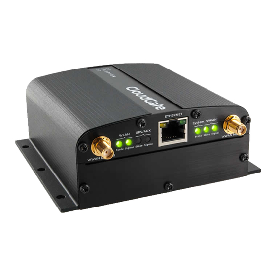
Page 7: Front And Back View
Front and Back View The CloudGate Base Unit is assembled in the top half of the device. The bottom half is available for the insertion of expansion cards. The front and back side of the CloudGate housing are closed by means of metal panels that are secured with Torx T10 screws. -
Page 8: Back View
A detailed description of the LEDs is given in the section about the LED Indicators. Bottom Front Panel The bottom front panel covers the front expansion slot and has to be removed when installing a Primary Expansion Card. Option provides a custom panel for the following primary expansion cards: Low Cost Serial Card Industrial Serial Card Ethernet Switch... - Page 9 reset button The functionality of the button is explained in the section about the reset button Behind the top back panel there is a socket for insertion of a SIM card. Please also refer to the section about the SIM card interface for more details. Bottom Back Panel The bottom back panel covers the back expansion slot and has to be removed when installing a Secondary Expansion Card.
-
Page 10: Led Indicators
LED Indicators Description WLAN State Indicates the connection status of the WLAN interface Off: not installed Orange: WLAN board = OK, client not connected and AP not enabled Orange blinking: AP disabled and Client connected / data traffic Red: board error/ (Any that causes AP or Client not to work) Green: AP enabled... - Page 11 Description Green: on, has fix Green flashing: GPS/Aux signal strength Indicates the signal strength of the GPS Off: no signal Orange: moderate GPS signal Red: bad GPS signal Green: good GPS signal Green flashing: n/a System State Indicates successful power on and device readiness Off: no power Orange:...
- Page 12 Red: The download was not successful.
-
Page 13: Ethernet Interface
1.4. Ethernet Interface This section describes the Ethernet interface on the CloudGate main board. Ethernet Interface RJ-45 receptacle tab on top 10/100 Mbps 100BASE-TX Auto-MDIX Pinout Yellow LED: Active when operating speed is 100 Mbps Inactive when operating speed is 10 Mbps or when not connected Green LED: Active when valid links are detected Blinks when activity is detected... - Page 14 Pin # Function Not used RX/TX- Not used Not used IMPORTANT: The auto-MDIX feature is always activated on the CloudGate. This feature automatically detects the required cable connection type (straight or crossed), and configures the connection appropriately, removing the need for crossover cables. In order for auto-MDIX to work correctly, auto-negotiation (auto speed and auto duplex) must be enabled on both sides of the link.
-
Page 15: Rf Specs And Antennas
RF specifications of the CloudGate 3G Americas Rev 3 Model: CG0198 WWAN Interface Supported Frequencies GSM, GPRS, and Edge bands: 850/900/1800/1900 MHz WCDMA bands: I, II, V, VI, VIII CDMA bands: BC0, BC1 & BC10 Output Power Power Class 4 (2W, 33dBm) for GSM, GPRS 850/900 MHz band Power Class 1 (1W, 30dBm) for GSM, GPRS 1800/1900 MHz band Power Class E2 (0.5W, 27dBm) for Edge 850/900MHz band Power Class E2 (0.4W, 26dBm) for Edge 1800/1900 MHz band... - Page 16 Frequency Range Allows all frequency bands which the integrator wants to use Performance Radiation pattern: Omni-directional Efficiency over all used frequencies: > 50% Maximum VSWR: < 2.5:1 with 50 ohm reference impedance Polarization Linear RF EXPOSURE WARNING To comply with regulatory requirements, please check the maximum allowed antenna gain for your your external antenna! The maximum gain is specified for each product in the certification information section of the CloudGate 3G Americas Rev 3.
-
Page 17: Gps Antenna
Efficiency Radiation pattern: Omni-directional Efficiency over all used frequencies: > 25% Maximum VSWR: < 2.5:1 with 50 ? reference impedance Polarization Linear Mutual coupling (main antenna and diversity antenna) Isolation: > 8dB Envelope correlation coefficient: < 0.5 GPS Antenna The CloudGate 3G EMEA rev 3 supports active GPS. When the diversity is disabled, the device will automatically feed 3V4 to the antenna port so that an active antenna can be connected. -
Page 18: Antenna Specs
Antenna recommendations for the CloudGate 3G Americas Rev 3 Model: CG0198 A number of good antennas are available on the market for use with the CloudGate. Below is a list of antennas which can be used as a reference for each functionality. All antennas listed below are made by Taoglas and are available via DigiKey Main WWAN and Diversity Antenna Grand-Tek OA-LTE-01-01-GTT... -
Page 19: Related Topics
Active GPS antenna Support GPS and Glonass Noise Figure < 2dB Preferably built-in pre-filter: this gives some freedom in positioning the two antennas (main antenna and GPS). No pre-filter means the antennas should be separated > 1m 15-30dB gain @ 3.4V Example Toaglass AA.161.301111 This antenna has a 3m extension cable for optimal positioning, e.g. -
Page 20: Power Requirements
Power Requirements Base Unit Power Supply The symbol on the label at the bottom side of the CloudGate shows the power requirements: Input voltage must be between 9V - 33V DC Internal electronic fuse limits the input current to 1.2A For the power cable between the external power supply unit and the CloudGate Option recommends to use a power cable that has a wire thickness of 22 AWG! SAFETY WARNING... -
Page 21: Power Consumption
Power Connector Drawing (PDF) Power Connector Datasheet (PDF) Pinout The following drawing shows the pinout of the power connector, seen from the terminal side. Pin # Function Input voltage Do not connect (reserved for future use) Do not connect (reserved for future use) Power Consumption You can find here a document describing all the different power consumption numbers Preventing Fuse Overload... - Page 22 with an output voltage higher than 15V, Option recommends using a special cable which will reduce the amplitude of these charge currents. This cable can be obtained at your CloudGate distributor. If the fifth digit of the serial number of the CloudGate is a "C", the CloudGate is an older model and susceptible to this remark.
-
Page 23: Internal Power Circuits
Internal Power Circuits The voltage applied by the power adapter to the CloudGate is converted into different voltage rails on the main board. Two different power circuits make five different voltage rails. Dedicated high current power circuit Provides two different voltage rails which both can deliver high current levels: V_PWR: At the power adapter input of the CloudGate there is an overvoltage protection circuit and a current limiter of 1.2A. - Page 24 translators, e.g. output buck between I/O signals converter (3V3, 1V8 from the processor and 1V2). The and circuitery on the maximum output main board or on current capability of the expansion cards each output of the converter is dependent on the loads on the other two outputs.
-
Page 26: Sim Card Interface
SIM Card Requirements The CloudGate has an integrated (U)SIM interface compatible with the ISO7816 IC card standard. The 3GPP standard defines three operational voltages for the supply voltage of the SIM card: 1.8V, 3V and 5V. The CloudGate supports two voltages: 1.8V and 3V. The 5V-only SIM cards are rarely used and are not supported by the CloudGate. -
Page 27: Reset Button
Reset Button On the back side of the unit there is a reset button behind the hole in the top panel (indicated by the "2" in the picture above). This button allows to restart the unit or to reset it to the factory settings: press and hold for less than ten seconds to reset the unit to the last working settings, press and hold for ten seconds or more to reset the unit to factory settings. -
Page 28: Mechanical Drawings
Mechanical Drawings 3D file of the CloudGate. 3D file of the front plate of the expansion cards Below you can find the dimensions of the CloudGate. - Page 29 The 6 mounting holes in the CloudGate housing allow mounting on a wall or on a DIN rail. See the details in the "Mounting" section of the CloudGate Installation Guide. Note 1: The front plate for the expansion cards, both at the front and at the back side of the CloudGate, are identical.
-
Page 30: Requirements
IP-65 Requirements Below you can find the parts for the encasing which are needed to fulfill the requirements for IP-65. All these parts can be ordered by TAKACHI: 1x box BCAK 203013G or BCPK 203013S, 1x plate BMP 2030P, 1 x screws (20pcs) MT4-8T, 1x bracket (2x4 pcs) BLF-2G(PC-GF) or CK-26P (metal SS) 3x cable gland MG-12S (3 inputs) -
Page 32: Environmental Specs
Environmental Specifications Operating temperature: -30°C to 70°C (*) see Safety Warning below Storage temperature: -40°C to 85°C Humidity operational: 5% - 95% non condensing Operating altitude: up to 2000m Safety Warning When the device is installed in a location where the environmental temperature can rise above 60°C, the temperature of the surface might reach high values and therefore under these conditions the user needs to warned in order to prevent accidental contact. -
Page 33: Shock Resistance
Shock Resistance The next tests have been performed on the CloudGate and passed: • EUT state: operational • Frequency range: 10 … 2000Hz • Overall acceleration: 3.6Grms • Crest Factor: 3 • Orientation: 3 axis, X / Y / Z •... -
Page 34: Certifications & Approvals
Certification information for CloudGate 3G Americas Rev Model: CG0198 This page offers an overview of the country certifications and operator approvals obtained per region. This CloudGate model is approved for use in the countries listed below. For use in other countries, please consult your sales contact. Canada United States Before installing your CloudGate device, read the Safety Guidelines section in the... - Page 35 type and its gain should be so chosen that the equivalent isotropically radiated power (e.i.r.p.) is not more than that necessary for successful communication. This radio transmitter, IC 7830A-PXS8, has been approved by Industry Canada to operate with the antenna types listed below with the maximum permissible gain and required antenna impedance for each antenna type indicated.
-
Page 36: United States
2.51 dBi dans la bande SCP (1900MHz) En plus, le produit doit être installé de manière à assurer une distance de séparation de 20 cm minimum entre le corps de l’utilisateur et les antennes. United States The CloudGate 3G Americas Rev 3 (CG0198) can be used in the USA and complies with the applicable FCC rule parts. - Page 37 Exposure Information to Radio Frequency Energy Users concerned with the risk of Radio Frequency exposure may wish to limit the duration of their calls and to position the antenna as far away from the body as is practical. Modifications Any changes or modifications made to this device that are not expressly approved by Option could void the user's authority to operate the equipment.
Need help?
Do you have a question about the CloudGate CG0198 and is the answer not in the manual?
Questions and answers