
Related Manuals for Audiovox Rampage AMP-602


Summary of Contents for Audiovox Rampage AMP-602
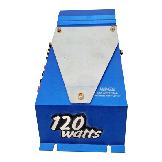
- Page 1 Model AMP-602 120 Watt 2-Channel Power Amplifier Ow ne ne ne ne ne r's Manual Manual Manual Manual Manual...
-
Page 2: Table Of Contents
INDEX Specifications ...1 Precautions ...2 Installation Instructions ...3 Wiring Instructions ...4 - 5 Input Wiring Diagram ...6 Output Wiring Diagram ...7 Operation ...8 Warranty ...9... -
Page 3: Specifications
60 dB Signal / Noise Ratio: 90 dB (A-Weighted) Input Impedance: Low-level 10K ohms High-level 100 ohms * Due to continuing improvement, Audiovox reserves the right to change features and design without notice. HELP! 1-800-645-4994 Monday - Friday Saturday Input Sensitivity: Low-level 200 mv. -
Page 4: Precautions
6. Make certain that the speakers to be used with this amplifier are capable of handling the output power (wattage) of the unit. Use of speakers not rated for the output of this amplifier may cause damage to or failure of the speakers for which Audiovox will not be liable. -
Page 5: Installation Instructions
INSTALLATION INSTRUCTIONS 1. Select a mounting area where the amplifier will have sufficient air circulation for proper cooling. Inadequate air circulation will cause the temperature of the amplifier to rise and will trigger the thermal protection mode. 2. Place the amplifier on the mounting surface and mark the locations of the four mounting holes as shown in the illustration. -
Page 6: Wiring Instructions
WIRING INSTRUCTIONS The power connections for this amplifier are made via screw tightened terminal blocks. Loosen the screw for the connection to be made and fully insert the wire (strip 1/2" of insulation from the end) under the respective screw on the side panel. - Page 7 WIRING INSTRUCTIONS 4. Speaker Connections Wire the speakers to the "Speaker Output" terminals as per the Output Wiring Diagram. For most applications, #18 gauge wire should be used for the speaker leads but in no case thinner than #20 gauge. When wiring the speakers, pay careful attention to the polarity of the terminals on the speakers and make certain they correspond to the polarity of the corresponding terminals on the amplifier.
-
Page 8: Input Wiring Diagram
INPUT WIRING DIAGRAM... -
Page 9: Output Wiring Diagram
WARNING! OUTPUT WIRING DIAGRAM l NEVER COMBINE (BRIDGE) OUTPUTS FOR USE WITH 2 SPEAKERS. l NEVER GROUND NEGATIVE SPEAKER LEADS TO CHASSIS GROUND. l FAILURE TO WIRE CORRECTLY MAY CAUSE DAMAGE TO THE AMPLIFIER. -
Page 10: Operation
OPERATION After initial set-up, the amplifier should not require any further adjustment unless there is a change in the car stereo or speaker system with which it is used. Power Indicator LED The Power Indicator LED will illuminate to indicate that the unit is connected to the battery and that the Remote Turn-On terminal is receiving +12 volts, thus turning on the amplifier. -
Page 11: Warranty
AUDIOVOX CORPORATION (the Company) warrants to the original retail purchaser of this product that should this product or any part thereof, under normal use and conditions, be proven defective in material or workmanship within 90 days from the date of original purchase, such defect(s) will be repaired or replaced with new or reconditioned product (at the Company's option) without charge for parts and repair labor. - Page 12 © 2001 Audiovox Electronics Corp., Hauppauge, NY 11788 Printed in Korea 128-6097...
Need help?
Do you have a question about the Rampage AMP-602 and is the answer not in the manual?
Questions and answers