Table of Contents
Advertisement
Quick Links
Operation and Service Manual
Distribution in the UK & Ireland
Characterisation,
Measurement &
Analysis
Stanford Research Systems
Lambda Photometrics Limited
Lambda House Batford Mill
Harpenden Herts AL5 5BZ
United Kingdom
E:
info@lambdaphoto.co.uk
W: www.lambdaphoto.co.uk
T:
+44 (0)1582 764334
F:
+44 (0)1582 712084
Analog PID Controller
Revision 2.3 • October 10, 2013
SIM960
Advertisement
Chapters
Table of Contents

Related Manuals for SRS Labs SIM960

Summary of Contents for SRS Labs SIM960
- Page 1 Operation and Service Manual Analog PID Controller SIM960 Stanford Research Systems Distribution in the UK & Ireland Lambda Photometrics Limited Revision 2.3 • October 10, 2013 Lambda House Batford Mill Harpenden Herts AL5 5BZ United Kingdom Characterisation, info@lambdaphoto.co.uk Measurement &...
- Page 2 Copyright c Stanford Research Systems, Inc., 2003 – 2013. All rights reserved. Stanford Research Systems, Inc. 1290–D Reamwood Avenue Sunnyvale, CA 94089 USA Phone: (408) 744-9040 • Fax: (408) 744-9049 www.thinkSRS.com • e-mail: info@thinkSRS.com Printed in U.S.A. Document number 9-01558-903 SIM960 Analog PID Controller...
-
Page 3: Table Of Contents
Contents General Information Safety and Precautions for Use ....Symbols ......Notation . - Page 4 Contents SIM960 Analog PID Controller...
-
Page 5: General Information
The user must assure that any failure or misapplication of the SIM960 cannot lead to a con- sequential failure of any interconnected equipment that could lead to loss of life or limb, or property damage. -
Page 6: Symbols
Symbols you may Find on SRS Products Symbol Description Alternating current Caution - risk of electric shock Frame or chassis terminal Caution - refer to accompanying documents Earth (ground) terminal Battery Fuse On (supply) Off (supply) SIM960 Analog PID Controller... -
Page 7: Notation
• Literal text other than command names is set as OFF. Remote command examples will all be set in monospaced font. In these examples, data sent by the host computer to the SIM960 are set as straight teletype font, while responses received by the host computer from the SIM960 are set as slanted teletype font. -
Page 8: Specifications
150 (±15 V), 80 (+5 V) General Characteristics Number of inputs Interface Serial (RS-232) through SIM interface Connectors BNC (3 front, 2 rear); DB–15 (male) SIM interface Weight 2.1 lbs 3.0 W × 3.6 H × 7.0 D Dimensions SIM960 Analog PID Controller... -
Page 9: Getting Started
1 Getting Started This chapter gives you the necessary information to get started quickly with your SIM960 Analog PID Controller. In This Chapter General ......1 – 2 Front Panel Operation . -
Page 10: General
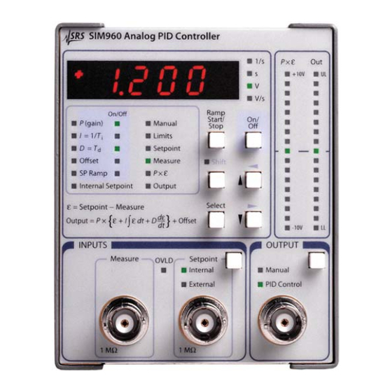
1 – 2 Getting Started 1.1 General The SIM960 is designed to maintain stability in systems requiring low noise and wide bandwidth. The controller design consists of a front end differential input amplifier, followed by an integrator and a differentiator, arranged in what is known as the “ideal” PID topology. - Page 11 1.2 Front Panel Operation 1 – 3 Figure 1.1: The SIM960 front panel. • The P, I, D, Offset , and SP Ramp parameters may be en- abled/disabled with [On/Off]. Each of these parameters has an additional indicator to the right of the descriptor to indicate the on/off...
-
Page 12: Inputs
SIM960 keeps the difference between the setpoint and measure inputs as small as possible, so the differential input range is unlikely to be exceeded. Before the SIM960 has been tuned for a given system, however, this may not be true. It is helpful to keep in mind that exceeding the ±1 V differential input range will... -
Page 13: Ramping
Connect the sensor output of the system to be controlled to the “Mea- sure” input of the SIM960 ˙ If an external setpoint is to be supplied, con- nect this to the “Setpoint” input, and use the button in the INPUTS section of the front panel to select “External”... -
Page 14: Bar Displays
The default configuration of the SIM960 can be restored in either of two ways: From the front panel, or via the remote interface. To restore from the front panel, first turn off the power to the SIM960 by switching its SIM900 Mainframe to “Standby,” then switch the... -
Page 15: Rear Panel Monitoring
This output is always available, even when the P term is disabled from the control law. It is also active when the main SIM960 output is set to Manual mode. 1.3.2 Input Setpoint Monitor The lower BNC is a copy of the internally generated setpoint voltage. -
Page 16: Sim Interface
SIM900 Mainframe via this connection, either through one of the internal mainframe slots, or the remote cable interface. It is also possible to operate the SIM960 directly, without using the SIM900 Mainframe. This section provides details on the interface. - Page 17 RS-232 serial port of a personal computer. Connect RXD from the SIM960 directly to RD on the PC, TXD directly to TD, and similarly RTS→RTS and CTS→CTS. In other words, a null-modem style cable is not needed.
- Page 18 (non-RS–232-standard) baud rates: 62500, 78125, 104167, 156250. Note that these rates are typically not accessible on a standard PC RS–232 port, but can be used between the SIM960 and the SIM900 Mainframe. SIM960 Analog PID Controller...
-
Page 19: Advanced Topics
2 Advanced Topics This chapter discusses a simple “closed-loop” tuning procedure, along with some of the advanced features of the SIM960 Analog PID Controller. In This Chapter PID Tuning Basics ....2 – 2 Ziegler-Nichols’... -
Page 20: Pid Tuning Basics
The difference between the Setpoint and Measure inputs is the error signal, ε ≡ Setpoint − Measure (Eqn 1.1). In the SIM960 the error signal is amplified by the proportional gain. The controller uses the amplified error, P ×... - Page 21 To see this, follow the effect of a small positive change at the process output. Since the process output Derivative gain is connected to the Measure input of the SIM960, a small positive Offset change would cause a negative change to ε. The resulting change at...
- Page 22 During the tuning process, it is important to keep in mind that the differential input range of the SIM960 is ±1.0 V. It is good practice to occasionally glance at the OVLD indicator to ensure the input amplifier is not saturated.
-
Page 23: Ziegler-Nichols' Tuning
The procedure is: • Switch the SIM960 into Manual mode, and then adjust until the process is stable and near the desired operating point. -
Page 24: Closed-Loop Tuning
The procedure is: • Switch the SIM960 into PID mode, with I and D both disabled. Choose a value for Setpoint around the desired operating point, and set P so some small value. -
Page 25: Anti-Windup And Conditional Integration
So stopping the integrator would hinder the controller’s effort to recover the process variable. The SIM960 uses a technique called “conditional integration:” Con- ditional integration only stops the integrator when the polarity of the error is such as to drive the integrator toward the saturated limit. -
Page 26: Bumpless Transfer
When I less transfer is only possible if the integral term is enabled. is turned on and the SIM960 is in Manual output mode, the input to the integrator is rerouted to integrate the difference between Manual and the (deselected) PID Control output. This effectively allows the PID Control to “track”... -
Page 27: Remote Operation
3 Remote Operation This chapter describes operating the module over the serial interface. In This Chapter Index of Common Commands ... . . 3 – 2 Alphabetic List of Commands ... . . 3 – 4 Introduction . -
Page 28: Index Of Common Commands
3 – 15 Amplified Error Monitor OMON? [i] 3 – 15 Output Monitor RFMT(?) {z} 3 – 15 Output Streaming Records Format SOUT [z] 3 – 16 Stop Streaming FPLC(?) {i} 3 – 16 Frequency of Power Line Cycle SIM960 Analog PID Controller... - Page 29 3 – 22 Wait LEXE? 3 – 22 Execution Error LCME? 3 – 23 Command Error LBTN? 3 – 23 Last Button TOKN(?) {z} 3 – 24 Token Mode TERM(?) {z} 3 – 24 Response Termination SIM960 Analog PID Controller...
-
Page 30: Alphabetic List Of Commands
3 – 17 Front Panel Display Enable EMON? [i] 3 – 15 Amplified Error Monitor FLOW(?) {z} 3 – 17 Flow Control FPLC(?) {i} 3 – 16 Frequency of Power Line Cycle GAIN(?) {f } 3 – 10 Proportional Gain SIM960 Analog PID Controller... - Page 31 3 – 16 Shift Status SMON? [i] 3 – 14 Setpoint Input Monitor SOUT [z] 3 – 16 Stop Streaming STRT z 3 – 13 Pause or continue ramping TERM(?) {z} 3 – 24 Response Termination SIM960 Analog PID Controller...
- Page 32 3 – 6 Remote Operation TOKN(?) {z} 3 – 24 Token Mode ULIM(?) {f } 3 – 13 Upper Output Limit WAIT i 3 – 22 Wait SIM960 Analog PID Controller...
-
Page 33: Introduction
Reset values of parameters are shown in boldface. 3.3.2 Buffers The SIM960 stores incoming bytes from the host interface in a 32- byte Input Buffer. Characters accumulate in the Input Buffer until a command terminator (either CR or LF ) is received, at which point the message is parsed and executed. -
Page 34: Commands
TERM CRLF TERM 3 —or— For queries that return token values, the return format (keyword or integer) is specified with the TOKN command. The following table summarizes the notation used in the command descriptions: SIM960 Analog PID Controller... -
Page 35: Commands
In these examples, all data sent by the host computer to the SIM960 are set as straight teletype font, while responses received the host computer from the SIM960 are set as slanted teletype font. The usage examples vary with respect to set/query, optional param- eters, and token formats. -
Page 36: Controller Settings Commands
GAIN does not modify whether the proportional term is enabled or disabled. For on/off control, see PCTL. Setting GAIN overrides the previous setting of APOL. −1 The allowed range for GAIN is 10 ≤ |P| ≤ 10 Example: GAIN +2.5E+2 SIM960 Analog PID Controller... - Page 37 The offset voltage can be set with millivolt resolution. Note that set- ting OFST does not modify whether the offset is enabled or disabled. For on/off control, see OCTL. The allowed range is −10.000 ≤ OFST +10.000. Example: OFST -12.3E-2; OFST? -0.123 SIM960 Analog PID Controller...
-
Page 38: Controller Configuration Commands
For on/off control of linear ramping, see RAMP. −3 ≤ RATE ≤ 10 The allowed range is 10 Example: RATE 2.2E-3 RATE? +0.2E-2 SIM960 Analog PID Controller... - Page 39 Set (query) the upper output limit {to f }, in volts. The upper limit can be set with 10 mV resolution. Note that, re- gardless of the operating mode of the SIM960 (see AMAN), the out- put voltage will always be clamped to remain less positive than the ULIM limit.
-
Page 40: Monitor Commands
Set (query) the lower output limit {to f }, in volts. The lower limit can be set with 10 mV resolution. The output voltage of the SIM960 will always be clamped to remain less negative than the LLIM limit. See ULIM for more details. - Page 41 The record format is SMON , MMON , EMON , OMON Example: RFMT ON SMON? 3; MMON? 3; EMON? 3; OMON? 3 +00.099909,-00.006053,+00.105601,+01.106135 +00.099909,-00.006031,+00.105615,+01.106123 +00.099915,-00.006001,+00.105636,+01.106151 SIM960 Analog PID Controller...
-
Page 42: Display Commands
MMN 10 ADC measurement of P-Amplified error EMN 11 ADC measurement of PID/Manual Output OMN 12 Example: DISP 1 SHFT(?) {z} Shift Status Set (query) the current shift status {to i=(OFF 0, ON 1)}. Example: SHFT? SIM960 Analog PID Controller... -
Page 43: Serial Communication Commands
PARI? NONE 3.4.8 Status commands The Status commands query and configure registers associated with status reporting of the SIM960. *CLS Clear Status *CLS immediately clears the ESR, CESR, and the SIM960 status reg- isters. Example: *CLS SIM960 Analog PID Controller... - Page 44 Set (query) the Standard Event Status Enable Register [bit i] {to j}. Example: *ESE 16 CESR? [i] Comm Error Status Query Comm Error Status Register [for bit i]. Upon executing a CESR? query, the returned bit(s) of the CESR register are cleared. Example: CESR? SIM960 Analog PID Controller...
- Page 45 (see Section 3.5.10). Example: ADSR? ADSE(?) [i], {j} A-to-D status enable register Set (query) the A-toD status enable register [bit i] {to j}. Example: ADSE 2 SIM960 Analog PID Controller...
-
Page 46: Interface Commands
The Interface commands provide control over the interface between the SIM960 and the host computer. *RST Reset Reset the SIM960 to its default configuration. The effect of this com- mand is equivalent to the following sequence of commands: • DISX ON • DISP PRP •... - Page 47 3 – 21 • LLIM -10.0 • INPT EXT • AMAN PID • TOKN OFF • SOUT The baud rate of the SIM960 is unaffected by *RST. The entire status model is also unaffected by *RST. Example: *RST CONS(?) {z} Console Mode Set (query) the Console mode {to z=(OFF 0, ON 1)}.
- Page 48 WAIT i Wait Wait i milliseconds before processing more commands from the host. When using the WAIT command, be careful to not overflow the input buffer of the SIM960 (see section 3.3.2). Example: SETP 0 RATE 0.1 SETP 1.0; WAIT 5000; SMON? +00.483159...
- Page 49 Query the last button that was pressed. The values returned are: Value Button no button pressed since last LBTN? [Setpoint] [Output] [Ramp Start/Stop] [Shift] [Select] [On/Off] [ ]/ [ ] [ ]/ [ ] Example: LBTN? SIM960 Analog PID Controller...
- Page 50 TOKN(?) {z} Token Mode Set (query) the Token Query mode {to z=(OFF 0, ON 1)}. If TOKN ON is set, then queries to the SIM960 that return tokens will return the text keyword; otherwise they return the decimal integer value.
-
Page 51: Status Model
OVLD INCR INSR INSE Figure 3.1: Status Register Model for the SIM960 Analog PID Con- troller. There are three categories of registers in the SIM960 status model: Condition Registers : These read-only registers correspond to the real-time condi- tion of some underlying physical property being monitored. -
Page 52: Status Byte (Sb)
Remote Operation 3.5.1 Status Byte (SB) The Status Byte is the top-level summary of the SIM960 status model. When masked by the Service Request Enable register, a bit set in the Status Byte causes the −STATUS signal to be asserted on the rear- panel SIM interface connector. -
Page 53: Standard Event Status (Esr)
Input Buffer. QYE : Query Error. Indicates data in the Output Queue has been lost. DDE : Device Dependent Error. Undefined for SIM960. EXE : Execution Error. Indicates an error in a command that was successfully parsed. Out-of-range parameters are an example. -
Page 54: Communication Error Status Enable (Cese)
3.5.7 Instrument Status (INCR) The Instrument Condition Register consists of 5 single-bit monitors of condition events within the SIM960. Bits in the INCR reflect the real-time values of their corresponding signals. Reading the entire register, or individual bits within it, does not affect the value of INCR. -
Page 55: Instrument Status (Insr)
This register is cleared at power-on. 3.5.10 Analog to Digital Status (ADSR) The Analog to Digital Status Register consists of 4 event flags; each of which is set by a corresponding conversion completion for one of SIM960 Analog PID Controller... -
Page 56: Analog To Digital Status Enable (Adse)
The ADSE acts as a bitwise AND with the ADSR register to produce the single bit ADSB message in the Status Byte Register (SB). It can be set and queried with the ADSE(?) command. This register is cleared at power-on. SIM960 Analog PID Controller... -
Page 57: Performance Tests
4 Performance Tests This chapter describes the tests necessary to verify the SIM960 is operating correctly and within specified calibration. In This Chapter Getting Ready ..... . . 4 – 2 Performance Tests . -
Page 58: Getting Ready
This divider will be used externally to the SIM960 to test the integral gain accuracy. The SIM960 should be given at least one hour to warm up after power is turned on, and care should be taken not to constrict the ventillation holes in the SIM900 mainframe. -
Page 59: Proportional Gain Accuracy
• Set the I parameter to 10 using INTG 1.0E5. • Turn on I control using ICTL ON. • Use a short BNC cable to connect the SIM960 Output to the Measure input. • Select “Internal” by pressing [Setpoint] on the front panel. -
Page 60: Derivative Gain Accuracy
4.2.4 Derivative Gain Accuracy Use the same connections as for the proportional gain accuracy test. Reset the SIM960 via the remote interface using *RST. Turn off the P (gain) control using PCTL OFF. Turn on the D control using DCTL ON. With the SR785 in swept sine mode and the source output amplitude at 0.5 V, measure the frequency response at the frequencies... -
Page 61: Integral Gain Accuracy
• Connect the top of the divider to the Output of the SIM960, connect the center of the divider to the Measure input of the SIM960, and connect the bottom of the divider to ground. This ground should be accessed at one of the BNC shields. -
Page 62: Calibration
In each case, the output display value should be within ±5 mV of the programmed manual output value. 4.3 Calibration If any of the preceeding tests fail, the SIM960 should be returned to the factory for recalibration. Contact Stanford Research Systems or an authorized representative before returning the SIM960. - Page 63 5 Parts Lists and Schematics This chapter presents a brief description of the SIM960 circuit design. A complete parts list and circuit schematics are included. In This Chapter Circuit Descriptions ....5 – 2 5.1.1...
-
Page 64: Circuitry
5–9 are the analog board. 5.1.1 Microcontroller The SIM960 is controlled by microcontroller U103. It is clocked at 10 MHz by the oscillator built around U102, which will track the reference +REF 10MHZ signal (if present) on JP103. -
Page 65: Proportional-Integral-Derivative
R615 in order to roughly match the switch resistance of each of the switches in U601. 5.1.5 Output Circuitry U807 is used to switch the ouput of the SIM960 between Manual and PID modes. The signal then passes through two cascaded diode limiter circuits. -
Page 66: Parts Lists
SIM960 output is referenced to ground via R863 (100k). U820A provides a buffered analog output of the P × ε signal at the back panel of the SIM960. Also, the output of U731A is passed to the back panel to provide an analog output of the internally generated setpoint signal. -
Page 67: Digital Board & Front Panel
3-00290-061 HDSP-A101 R111,R114,R118,R123,R151, 4-01503-100 R152,R153,R154,R155,R276, X101-X314 (41 total) 5-00299-100 R334 Y101 6-00571-020 10.000MHZ R112,R113,R122 4-01527-100 100K Y104,Y108,Y202,Y203,Y204, 4-01213-110 10.0K R115,R117,R119 4-01465-100 Y206,Y207,Y208,Y210,Y211, R128,R242 4-01309-110 100K Y229,Y252,Y253,Y256,Y258, R201,R205,R209,R212,R233, 4-01405-110 1.00M Y261,Y282,Y283,Y284,Y285 R235,R237,R239,R282,R286 PCB, SIM960 Digital Board 7-01258 SIM960 Analog PID Controller... -
Page 68: Analog Board
R845,R846 U822 3-00279-340 LT1010CN8 R616 4-01317-110 121K U901 3-01432 OPA4131 R618,R620,R621,R622,R623, 4-01561-100 2.7M U903,U902 3-00787-103 74HC595 R624,R717,R805 X509-X910 (90 total) 5-00299-100 R644,R643 4-00997-110 56.2 Y537-Y827 (16 total) 4-01213-110 10.0K R645,R646,R647,R648 4-01503-100 PCB, SIM960 Analog Board 7-01259 SIM960 Analog PID Controller... -
Page 69: Schematic Diagrams
Schematic diagrams follow this page. Distribution in the UK & Ireland Lambda Photometrics Limited Lambda House Batford Mill Harpenden Herts AL5 5BZ United Kingdom Characterisation, info@lambdaphoto.co.uk Measurement & W: www.lambdaphoto.co.uk +44 (0)1582 764334 Analysis +44 (0)1582 712084 SIM960 Analog PID Controller...
Need help?
Do you have a question about the SIM960 and is the answer not in the manual?
Questions and answers