Table of Contents
Advertisement
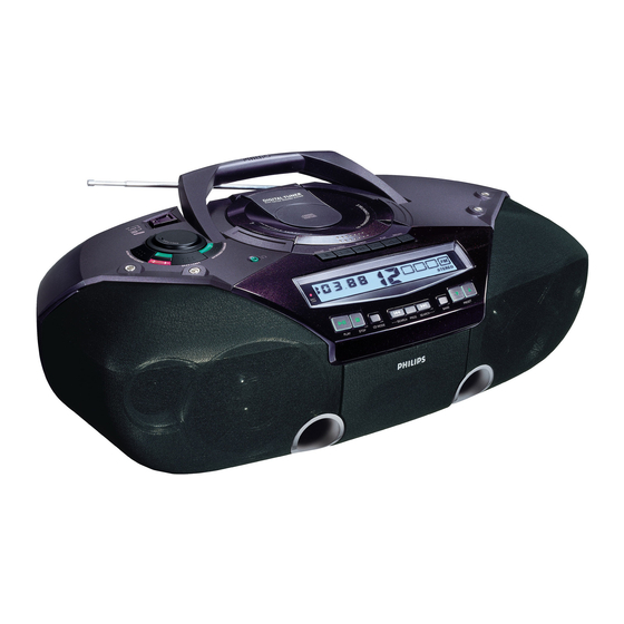
CD Stereo Radio Recorder
TABLE OF CONTENTS
Handling chip components and safety
Technical Specification & Service Tools
..................................................
Service Measurement
................................................
Connections & Controls
.................................................
Instructions for use
...................................................
Disassembly Diagram
........................................
CD Service Test Program
.............................................................
Block Diagram
...........................................................
Wiring Diagram
FRONT BOARD
.......................................................
circuit diagram
.......................................................
layout diagram
AF & POWER BOARD
.......................................................
circuit diagram
.......................................................
layout diagram
FEATURE BOARD
.......................................................
circuit diagram
.......................................................
layout diagram
Safety regulations require that the set be restored to its original
condition and that parts which are identical with those specified
be used.
C
Copyright 1995 Philips Consumer Electroncis B.V. Eindhoven, The Netherlands
All rights reserved. No part of this publication may be reproduced, stored in a retrieval
system or transmitted, in any form or by any means, electronic, mechanical, photocopying,
or otherwise without the prior permission of Philips.
Published by SS 0115 Service Audio
PCS 107 271
chapter
.............................
1 - 1
..........................
2 - 1
2 - 2
3 - 1
3 - 2 to 3 - 6
4 - 1
4 - 2 to 4 - 3
5 - 1
5 - 2
6 - 1
6 - 2
7 - 1
7 - 2
8 - 1
8 - 1
Printed in The Netherlands
TUNER BOARD
.......................................................
circuit diagram
.......................................................
layout diagram
REOCRDER BOARD
.......................................................
circuit diagram
.......................................................
layout diagram
CD MODULE
.......................................................
circuit diagram
.......................................................
layout diagram
EXPLODED VIEWS DIAGRAM
.................................................................
cabinet
............................................................
tape deck
.....................................................
Mechanical partslist
...............................................
Electrical partslist
Copyright reserved
Subject to modification
AZ2030
AZ2035
all versions
chapter
9 - 1
9 - 2
10 - 1
10 - 2
11 - 2
11 - 1
12 - 1
12 - 2
12 - 2
13 - 1 to 13 - 5
CLASS 1
LASER PRODUCT
3140 785 22580
GB
Advertisement
Table of Contents

Related Manuals for Philips AZ2030


Summary of Contents for Philips AZ2030
- Page 1 LASER PRODUCT Copyright 1995 Philips Consumer Electroncis B.V. Eindhoven, The Netherlands All rights reserved. No part of this publication may be reproduced, stored in a retrieval system or transmitted, in any form or by any means, electronic, mechanical, photocopying, or otherwise without the prior permission of Philips.
-
Page 2: Handling Chip Components
HANDLING CHIP COMPONENTS © ñ WARNING WAARSCHUWING All ICs and many other semiconductors are susceptible to Alle IC´s en vele andere halfgeleiders zijn gevoelig voor electrostatic discharges (ESD). Careless handling during electrostatische ontladingen (ESD). repair can reduce life drastically. Onzorgvuldig behandelen tijdens reparatie kan de levensduur When repairing, make sure that you are connected with the drastisch doen vermindern. -
Page 3: Technical Specifications
TECHNICAL SPECIFICATIONS GENERAL TUNER - AM SECTION Tuning range MW : 531 - 1602 kHz Mains voltage -/00/14 : 230 V -/17 : 530 - 1700 kHz -/01/11/16 : 120/230 V LW : 153 - 279 kHz -/05/10 : 240 V IF frequency : 468 kHz ±... -
Page 5: Connections And Controls
CONNECTIONS AND CONTROLS PCS 107 273... - Page 6 INSTRUCTION FOR USE PCS 107 274...
- Page 7 INSTRUCTION FOR USE PCS 107 275...
- Page 8 INSTRUCTION FOR USE PCS 107 276...
- Page 9 INSTRUCTION FOR USE PCS 107 277...
- Page 10 INSTRUCTION FOR USE PCS 107 278...
-
Page 11: Disassembly Diagram
DISASSEMBLY DIAGRAM A. To remove the Top Cabinet and Front Panel Assy A7. Lift from the centre back (ventilation slot) to remove Top Cabinet (see fig. 1 & 2) B. To separate Top Cabinet and Top Cabinet Bracket C. To separate Front Panel Assy and Top Cabinet Bracket D. - Page 12 CD SERVICE TEST PROGRAM To enter Service CD TEST TUNER TEST To enter Service Testprogramm hold Testprogramm hold PLAY & MODE buttons PLAY & MODE buttons STOP button pressed in any step returns depressed while switching depressed while switching to begin of Service Testprogram. CD mode on.
- Page 13 Abbreviations and Pin-description of CD Ics Abbreviations and Pin-description of CD Ics SERVO PROCESSOR SAA7325H SERVO PROCESSOR SAA7325H SYMBOL DESCRIPTION SYMBOL DESCRIPTION HFREF comparator common mode input microcontroller interface R/W and load control line input (4-wire bus mode) HFIN comparator signal input SILD microcontroller interface R/W and load control line input (4-wire bus mode) ISLICE...
-
Page 14: Block Diagram
BLOCK DIAGRAM For AZ2035 only For AZ2030 only PCS 107 281... -
Page 15: Wiring Diagram
WIRING DIAGRAM PCS 107 282... -
Page 16: Front Board - Circuit Diagram
FRONT BOARD - CIRCUIT DIAGRAM PCS 107 283... -
Page 17: Front Board - Layout Diagram
FRONT BOARD - LAYOUT DIAGRAM PCS 107 284... - Page 18 AF & POWER BOARD - CIRCUIT DIAGRAM PCS 107 285...
- Page 19 AF & POWER BOARD - LAYOUT DIAGRAM 300 F6 3333 H5 9227 B6 2310 D2 3356 H6 301 D3 3337 H5 9228 A5 2312 D2 3357 C6 1300 E2 3339 H5 9229 E6 2320 A6 3358 C6 1301 C1 3352 H5 2325 A7 3360 E2 1302 A5...
- Page 20 FEATURE BOARD - CIRCUIT DIAGRAM PCS 107 287...
- Page 21 FEATURE BOARD - LAYOUT DIAGRAM PCS 107 288...
- Page 22 TUNER BOARD ECO6 - CIRCUIT DIAGRAM 1105 A1 5123 G5 1121 F14 5130 E6 1122 E14 5131 C6 TUNER BOARD ECO6 / 2101 A3 6103 A3 PORTABLE AUDIO 2103 C7 6105-1 B4 2104 A3 6105-2 G6 VERSION PROGRAMMING COMPONETS 2106 B4 6106 B4 2107 F4 6120 B13...
-
Page 23: Tuner Board Eco6 - Layout Diagram
TUNER BOARD ECO6 - LAYOUT DIAGRAM TUNER ADJUSTMENT TABLE ( ECO6 FM/MW- and FM/MW/LW - versions with ferrite antenna) Waverange Input frequency Input Tuned to Adjust Output Scope/Voltmeter 1105 B7 2106 D6 2129 C5 2155 C5 2191 A2 5102 D7 5110 B3 5114 B3 5122 B6... -
Page 24: Recorder Board - Circuit Diagram
10-1 10-1 RECORDER BOARD - CIRCUIT DIAGRAM 1707 C 3 1709 A14 2706 B 4 2711 F 6 2719 C 8 2727 F 7 2733 H13 2750 D 6 3703 D 3 3712 E 7 3720 F 7 3730 F12 3743 C 9 3761 G 6 7705 G 4... -
Page 25: Recorder Board - Layout Diagram
10-2 10-2 RECORDER BOARD - LAYOUT DIAGRAM 71 A 1 2729 C 5 3733 B 2 9756 C 3 72 D 5 2730 D 1 3734 D 5 9757 D 3 73 A 5 2731 C 1 3735 D 3 9759 D 4 74 A 1 2732 B 1... - Page 26 11-1 11-1 CD99 DA11 - LAYOUT DIAGRAM 1800 3703 3876 CD99 Board component side view CD99 Board copper side view 1801 3704 3877 1810 3705 3878 1821 3728 3879 1822 3745 3880 2840 5802 1823 3750 3881 1824 3751 3882 2701 3757 3883...
- Page 27 11-2 11-2 11-2 CD99 DA11 - CIRCUIT DIAGRAM 1800 D1 2806 E4 2813 E9 2820 B10 2827 C14 2834 F5 2841 C1 2865 D5 2875 D5 3801 A1 3808 A2 3815 E5 3822 E7 3829 A11 3838 D14 3845 G12 3852 F5 3859 H5 3890 B4...
-
Page 28: Cabinet
12-1 12-1 12-1 EXPLODED VIEW DIAGRAM - CABINET SCREW LIST 1. Screw Tapping (3mm A/F Hexgonal Type) 2. Screw Tapping (5mm A/F Hexgonal Type) 3. C2 x 8 7 (6x) 3 (2x) 4. C2.5 x 10 5. C3 x 8 3 (4x) 6. -
Page 29: Mechanical Partslist - Cabinet
4822 691 10612 TAPE DECK MECHANISM 461 9965 000 08534 SPK CLOTH FRAME (L) 9965 000 08506 REC SPRING 462 9965 000 08535 SPK CLOTH FRAME (R) (FOR AZ2030) 9965 000 08494 CASS KNOB (PAUSE) 462 9965 000 08587 SPK CLOTH FRAME (R) (FOR AZ2035) 9965 000 08495 CASS KNOB (STOP) 463 9965 000 08509 COMP.SPRING (+,-) - Page 30 13-1 13-1 ELECTRICAL PARTSLIST - FRONT BOARD ELECTRICAL PARTSLIST - AF & POWER BOARD ELECTRICAL PARTSLIST - FEATURE BOARD - FILTER & INDUCTORS - - COILS - - RESISTOR - - IC & TRANSISTORS - L201 9965 000 08562 INDUCTOR 2.2µH 5300 9965 000 08569 RF COIL 0.36µH VR601...
- Page 31 13-2 13-2 ELECTRICAL PARTSLIST - TUNER BOARD ECO6 ELECTRICAL PARTSLIST - TUNER BOARD ECO6 - CAPACTORS - - CAPACTORS - - RESISTORS - - IC & TRANSISTORS - 2101 4822 126 13692 47pF 1% NP0 63V 2188 4822 122 33177 10nF 20% X7R 50V 3181 4822 051 10102...
- Page 32 13-3 13-3 ELECTRICAL PARTSLIST - CD99 DA11 ELECTRICAL PARTSLIST - CD99 DA11 - CAPACITORS - - CAPACITORS - - RESISTORS - - RESISTORS - 2801 482212441751 47µF 2855 482212411912 220µF 20% 6,3V 3826 482205120273 0,1W 3883 482205110102 1K 2% 0,25W 2802 482212441751 47µF...
- Page 33 13-4 ELECTRICAL PARTSLIST - CD99 DA11 - RESISTORS - 4888 482205120008 Jumper 4889 482205120008 Jumper - COILS & FILTERS - 1810 482224273557 Filter CST8,46MTW-TF01 5803 482215711231 Coil LAN02TB1R0J - DIODES - 6877 482213011564 Diode UDZ3.9B - IC & TRANSISTORS - 7800 482220917324 IC SAA7325H...
- Page 34 13-5 ELECTRICAL PARTSLIST - RECORDER BOARD - CAPACITORS - - RESISTORS - 2703 482212481151 22µF 3727 482211652256 0,5W 2704 482212481151 22µF 3730 482211683868 150R 0,5W 2706 482212440433 47µF 20% 25V 3731 482211652291 0,5W 2707 482212440196 220µF 20% 16V 3732 319801101590 0,5W 2708 482212440433...
Need help?
Do you have a question about the AZ2030 and is the answer not in the manual?
Questions and answers