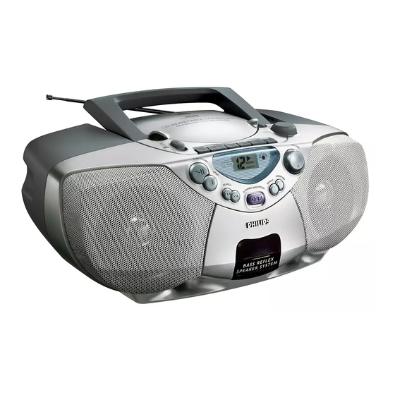
Philips AZ1008 Service Manual
Cd stereo radio recorder
Hide thumbs
Also See for AZ1008:
- User manual (42 pages) ,
- Instruction manual (42 pages) ,
- Specifications (2 pages)
Advertisement
Table of Contents
CD Stereo Radio Recorder
TABLE OF CONTENTS
Handling chip components and safety
Technical Specification & Service Tools
..................................................
Service Measurement
................................................
Connections & Controls
.................................................
Instructions for use
.............................................................
Block Diagram
............................................................
Wiring Diagram
FRONT BOARD
.......................................................
circuit diagram
........................................................
layout diagram
COMBI BOARD
...................................................
circuit diagram
...................................................
layout diagram
Safety regulations require that the set be restored to its original
condition and that parts which are identical with those specified
be used.
C
Copyright 1995 Philips Consumer Electroncis B.V. Eindhoven, The Netherlands
All rights reserved. No part of this publication may be reproduced, stored in a retrieval
system or transmitted, in any form or by any means, electronic, mechanical, photocopying,
or otherwise without the prior permission of Philips.
Published by SS 0052 Service Audio
PCS 107 163
chapter
.............................
1 - 1
..........................
2 - 1
2 - 2
3 - 1
3 - 2 to 3 - 4
4 - 1
5 - 1
6 - 1
6 - 1
7 - 1, 7 - 3
7 - 2, 7 - 4
Printed in The Netherlands
TUNER BOARD
.......................................................
circuit diagram
.......................................................
layout diagram
REOCRDER BOARD
.......................................................
circuit diagram
.......................................................
layout diagram
EXPLODED VIEW DIAGRAM
.................................................................
cabinet
............................................................
tape deck
.....................................................
Mechanical partslist
...............................................
Electrical partslist
Copyright reserved
Subject to modification
AZ1008
all versions
chapter
8 - 1
8 - 2
9 - 1
9 - 2
10 - 1
10 - 2
10 - 2
11 - 1 to 11 - 3
CLASS 1
LASER PRODUCT
3140 785 22520
GB
Advertisement
Table of Contents

Related Manuals for Philips AZ1008


Summary of Contents for Philips AZ1008
- Page 1 LASER PRODUCT Copyright 1995 Philips Consumer Electroncis B.V. Eindhoven, The Netherlands All rights reserved. No part of this publication may be reproduced, stored in a retrieval system or transmitted, in any form or by any means, electronic, mechanical, photocopying, or otherwise without the prior permission of Philips.
- Page 2 HANDLING CHIP COMPONENTS © ñ WARNING WAARSCHUWING All ICs and many other semiconductors are susceptible to Alle IC´s en vele andere halfgeleiders zijn gevoelig voor electrostatic discharges (ESD). Careless handling during electrostatische ontladingen (ESD). repair can reduce life drastically. Onzorgvuldig behandelen tijdens reparatie kan de levensduur When repairing, make sure that you are connected with the drastisch doen vermindern.
-
Page 3: Technical Specifications
TECHNICAL SPECIFICATIONS GENERAL TUNER - AM SECTION Mains voltage -/00/05/14 : 230 V Tuning range : 512 - 1635 kHz -/10 : 240 V -/17 : 520 - 1730 kHz -/01/11/16 : 120 / 230 V IF frequency : 468 kHz ± 3 kHz -/17 : 120 V Sensitivity : 1500 µV/m at 26dB S/N... -
Page 9: Block Diagram
BLOCK DIAGRAM +TUNER ATM5 2 BAND TUNER +A +A_ON ECO-MTF-SD POWER AMP ROTARY VOLUME TAPE MODULE TA8227P TAPE 8 OHM LOUDSPEAKER +A_ON CD MX Control panel TRANSFORMER +A_ON RECTIFIER 1N4003 +TUNER 1N4003 TAPE TAPE 1.5 V X 6 PCS 107 169... -
Page 10: Wiring Diagram
WIRING DIAGRAM BATTERY COMPARTMENT CD DRIVE VAM2201 CD DOOR SW 8254 100MM 8801 8803 180MM 180MM 140MM 80MM 8253 8802 1256 PH-B 1255 EH-B CD LAYOUT CELL 1255 EH-B TUNER MODULE 8101 100MM 1260 PH-B 8252 ATM5 2BAND AF BOARD 120MM 1259 1254... -
Page 11: Circuit Diagram
FRONT BOARD - CIRCUIT DIAGRAM FRONT BOARD - LAYOUT DIAGRAM 1250 E1 1251 C4 1400 B1 1401 B1 1402 B1 1403 B2 7403 REPEAT 1404 C2 THD5064 1405 C1 PROGRAM 1406 A4 2250 D2 2251 F2 2252 E2 1 2 3 4 5 6 7 FE-ST-VK-N 2253 F2 1406... - Page 12 COMBI BOARD (Control / CD Part) - CIRCUIT DIAGRAM L H14 3850 B2 R H14 3851 A1 +A G14 3852 A1 5V G14 3853 B2 0001 H13 3854 C3 CONTROL / CD PART 0002 H13 3855 C2 0003 H14 3856 B2 3860 2Vref 0004 H14...
- Page 13 COMBI BOARD (Solider Side) - LAYOUT DIAGRAM LOUDSPEAKER BOARD - CIRCUIT DIAGRAM DIPMATE 1260 1261 EH-B To Speaker From Combi board LOUDSPEAKER BOARD - LAYOUT DIAGRAM PCS 107 173...
- Page 14 COMBI BOARD - CIRCUIT DIAGRAM 1252 B2 1256 G4 2254 B10 2258 B11 2262 C12 2267 H10 2271 G6 2276 C8 2281 C10 3260 B3 3264 D3 3268 C11 3274 H9 3279 H9 3289 G7 3294 B3 3298 C8 6250 D3 6254 F5 6259 G7 6263 H10...
- Page 15 COMBI BOARD (Component Side) - LAYOUT DIAGRAM CD DOOR SWITCH - CIRCUIT DIAGRAM DIPMATE CD door switch 1805 1806 SPPB51 CD DOOR SWITCH - LAYOUT DIAGRAM PCS 107 175...
- Page 16 TUNER BOARD ATM5 - CIRCUIT DIAGRAM 1001 A4 1104 E3 1110 B11 5107a 5107b 5107c 2101 A4 SFE10.7MS3 SFE10.7MS2 CDA10.7MC1 T003 1001 FM-RF All SMD Transistors 2102 A4 180KHz 230KHz 2103 D4 2104 G7 2105 A5 2106 F10 7102 2108 C3 Top View from BC847B Solder Side...
- Page 17 TUNER BOARD ATM5 - LAYOUT DIAGRAM TUNER ADJUSTMENT TABLE FM/MW versions Waverange Input Frequency Input Set tuned to Adjust Measure on Scope / Counter 1001 E1 2122 1104 A2 3101 OSCILLATOR 1110 F6 5101 2103 D2 5102 lower band end 5104 87,35 MHz 2104 D1...
- Page 18 RECORDER BOARD - CIRCUIT DIAGRAM 1707 C 3 1709 A14 2706 B 4 2711 F 6 2719 C 8 2727 F 7 2733 H13 2750 D 6 3703 D 3 3712 E 7 3720 F 7 3730 F12 3743 C 9 3761 G 6 7705 G 4 8702 E 1...
- Page 19 RECORDER BOARD - LAYOUT DIAGRAM 71 A 1 2729 C 5 3733 B 2 9756 C 3 72 D 5 2730 D 1 3734 D 5 9757 D 3 73 A 5 2731 C 1 3735 D 3 9759 D 4 74 A 1 2732 B 1 3736 B 5...
-
Page 20: Cabinet
10-1 10-1 EXPLODED VIEW DIAGRAM - CABINET 38 37 36 35 50 63 27 18 PCS 107 180... -
Page 21: Tape Deck
10-2 10-2 MECNANICAL PARTSLIST - CABINET EXPLODED VIEW DIAGRAM - TAPE DECK 9965 000 07504 Cass Door 9965 000 07512 Rod Antenna 9965 000 07479 Cass Door Lens 9965 000 07505 CD Door Spring 9965 000 07480 Pointer 9965 000 07506 Cass Door Spring 9965 000 07481 Gear PVC 9965 000 07507 Cass Tape Spring 9965 000 07482 Gear Big... - Page 22 11-1 11-1 ELECTRICAL PARTSLIST - FRONT BOARD ELECTRICAL PARTSLIST - MAIN BOARD ELECTRICAL PARTSLIST - MISCELLANEOUS - RESISTORS - - COIL - - CAPACITORS - 3256 9965 000 07514 Rotary Volume.50KB X2 5200 4822 157 11012 Inductor 2.2µH 2001 5322 122 32654 22nF X10% 7R 63V 2002 5322 122 32654 22nF X10% 7R 63V - COIL -...
- Page 23 11-2 ELECTRICAL PARTSLIST - TUNER BOARD ATM5 - CAPACITORS - - COILS & FILTER - 2101 4822 126 13193 4,7nF 10% X7R 63V 5101 4822 157 70513 Coil 2102 4822 122 33777 47pF 5% NP0 63V 5102 2422 535 94985 Ind Fxd 64µH 5% 2103 4822 124 40248 10µF 20% 63V 5104...
- Page 24 11-3 ELECTRICAL PARTSLIST - RECORDER BOARD - CAPACITORS - - RESISTORS - 2703 4822 124 81151 22µF 50V 3727 4822 116 52256 2K2 5% 0,5W 2704 4822 124 81151 22µF 50V 3730 4822 116 83868 150R 5% 0,5W 2706 4822 124 40433 47µF 20% 25V 3731 4822 116 52291 56K 5% 0,5W...
Need help?
Do you have a question about the AZ1008 and is the answer not in the manual?
Questions and answers