Gallagher 3E3446 M5800i Instructions Manual
Energizer electric fence charger i series
Hide thumbs
Also See for 3E3446 M5800i:
- Instructions manual (153 pages) ,
- Instructions manual (153 pages) ,
- Instructions manual (54 pages)
Table of Contents
Advertisement
Advertisement
Table of Contents

Related Manuals for Gallagher 3E3446 M5800i


Summary of Contents for Gallagher 3E3446 M5800i
- Page 1 FENCE ENERGIZER i SERIES Instructions - ENG...
- Page 2 3E3618 - Edi on 6 December 2015 DISCLAIMER: Whilst every eff ort has been made to ensure accuracy, neither Gallagher Group Limited nor any employee of the company shall be liable on any ground whatsoever to any party in respect of decisions or ac ons they may make as a result of using this informa on.
-
Page 3: Table Of Contents
Contents 3E3446 M5800i/M10000i Energizer User Manual Important Informa on ....................... 5 How the Energizer works ......................7 Installa on Guide ........................8 Understanding Your Energizer ....................11 Understanding Your Energizer Controller ................12 Op onal Accessories ....................... 18 Troubleshoo ng ........................19 3E2749 Remote &... -
Page 5: Important Informa On
• Regularly inspect the supply cord and energizer for any damage. If found damaged in any way, immediately cease use of the energizer and return it to a Gallagher Authorised Service Centre for repair in order to avoid a hazard. - Page 6 This energizer complies with interna onal safety regula ons and is manufactured to interna onal standards. Gallagher reserves the right to make changes without no ce to any product specifi ca on to improve reliability, func on or design. E & OE.
-
Page 7: How The Energizer Works
Gallagher 3E3618 i Series Energizer User Manual HOW THE ENERGIZER WORKS The energizer sends electrical pulses along the fence line, about one second apart. These pulses give the animal a short, sharp, but safe shock. The shock doesn’t harm the animal. It is suffi ciently memorable that the animal never forgets the shock, and will avoid the fence. -
Page 8: Installa On Guide
Gallagher 3E3618 i Series Energizer User Manual INSTALLATION GUIDE Energizer Controller Mount the controller on a fl at surface within 3m (10 ) of the energizer, or up to 50m (160 ) if using an RJ-12 extension cable*. The controller is suitable for indoor and outdoor use. - Page 9 Earth Stake (G879) and then clamp the exposed wire to each stake using an Earth Clamp (G876). Tighten the clamp. For further instruc ons on the earth (ground) system see the Gallagher Power Fence™ Manual. Note: Poor grounding can cause interference on telephone lines, radios and televisions.
- Page 10 Screw the terminal closed, ensuring the wire is fi rmly clamped. A ach the other end of the cable to the fence using a Joint Clamp (G603). For instruc ons on fence installa on see the Gallagher Power Fence™ Manual or go to www.gallagher.co.
-
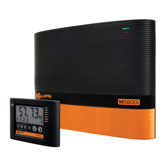
Page 11: Understanding Your Energizer
Gallagher 3E3618 i Series Energizer User Manual UNDERSTANDING YOUR ENERGIZER Fence Fault LED Power Supply Power On LED Flashing red when the 220 - 240VAC. Internal protec on Green when the energizer has detected a against poor power supplies energizer is powered fence fault. -
Page 12: Understanding Your Energizer Controller
Gallagher 3E3618 i Series Energizer User Manual UNDERSTANDING YOUR ENERGIZER CONTROLLER Voltage Display Current Display Shows energizer / earth / fence zones voltage Shows the amount of load on the energizer / fence zones Status LED Quickscan Bargraph Provides quick... - Page 13 Gallagher 3E3618 i Series Energizer User Manual Current Display The output current indicates how hard your energizer is working. When your fence is in good condi on this reading will be low, typically under 15 Amps. As the load on the fence increases the current will rise and output voltage will fall. The output current will typically change with fence condi ons, seasonal grass growth and wet weather.
- Page 14 Gallagher 3E3618 i Series Energizer User Manual Using The Energizer Controller Energizer Output and Alarms The energizer output is the default screen display mode. The zone indicator arrow is highligh ng the energizer zone ( ) and the energizer output voltage is 7.3KV in this case.
- Page 15 fi nd faults before your fence becomes ineff ec ve (voltage too low), Gallagher recommend se ng the current alarm 10A above normal opera on. Many events can cause the current to increase, including rainfall, grass growth, broken fences and failed insulators.
- Page 16 0.2-0.3KV is achieved. In dry condi ons or areas with low mineral content soil an earth return system may be required as described in the Gallagher Power Fence™ Manual or visit www.gallagher.co.
- Page 17 Gallagher 3E3618 i Series Energizer User Manual Fence Zone 1 - 6 View the Fence Zone performances by pressing the naviga on bu ons (< or >) un l the zone indica on arrow is highligh ng the desired fence zone (1 - 6). The fence zones voltage, current and alarm informa on is displayed in the same way as the Energizer output informa on.
-
Page 18: Op Onal Accessories
Controller indica ng that zone is below the set alarm voltage. Gallagher Energizer Remote and Fault Finder G50700 The Gallagher Energizer Remote and Fault Finder displays which zone(s) are in fault and can then be used to locate the fault within that zone. Power to the fence at the fault loca on can be turned off... -
Page 19: Troubleshoo Ng
Gallagher 3E3618 i Series Energizer User Manual TROUBLESHOOTING Problem Causes Solution Energizer has started to run The internal temperature of Mount the energizer in a cool slowly the energizer is too high area, out of direct sun and with adequate ven la on... - Page 21 ENERGIZER REMOTE & FAULT FINDER...
-
Page 22: 3E2749 Remote & Fault Finder User Manual
Contents 3E2749 Remote & Fault Finder User Manual Remote Readings ........................23 Installing the ba ery ........................ 24 Features ........................... 24 Checking your fence and fi nding faults ..................25 Detec ng Alarms ........................26 Turning the Energizer On / Off (Standby) ................26 Using your Remote with mul ple Energizers ................ -
Page 23: Remote Readings
Gallagher 3E3618 i Series Energizer User Manual REMOTE READINGS Liquid Crystal Display This is the full range of symbols. The meaning of each symbol is detailed below. 1 2 3 4 5 6 Standby Indicates the energizer is in Standby mode . -
Page 24: Installing The Battery
The remote ba ery has a life of approximately 6 months. A fl at ba ery may give false measurements so replace the ba ery when the icon shows. FEATURES The Gallagher Energizer Remote and Fault Finder enables you to do the following: • Measure fence voltage and current •... -
Page 25: Checking Your Fence And Fi Nding Faults
Gallagher 3E3618 i Series Energizer User Manual CHECKING YOUR FENCE AND FINDING FAULTS Place the fence wire in the fence connec ons slot. Hold un l the following informa on appears on the display. Gives the current on the fence in Amps... -
Page 26: Detec Ng Alarms
Gallagher 3E3618 i Series Energizer User Manual DETECTING ALARMS You can communicate with the devices opera ng on your fence by pressing the bu on. System status is “OK” No alarms Energizer status Not in alarm Connected fence zones - None are in alarm System status is “AL”... -
Page 27: Using Your Remote With Mul Ple Energizers
Gallagher 3E3618 i Series Energizer User Manual USING YOUR REMOTE WITH MULTIPLE ENERGIZERS The Remote has nine channels that can be “tuned in” to a specifi c energizer, enabling the Remote to control up to nine energizers. Note: You do NOT need to register your Remote with the Energizer if you are only using one Energizer. - Page 28 Gallagher 3E3618 i Series Energizer User Manual Use this table to record which channel number is set to each energizer. Channel Energizer...
-
Page 29: Understanding Your Electric Fence
Gallagher 3E3618 i Series Energizer User Manual UNDERSTANDING YOUR ELECTRIC FENCE Compare your electric fence to a water supply system. Fence Voltage = Water Pressure Electric Current = Water Volume/Flow A perfectly performing Electric fence is similar to a water system that has a pressure pump (Energizer) at one end and a bung at the other. - Page 31 FENCE MONITOR...
-
Page 32: 3E2748 Fence Monitor User Manual
Contents 3E2748 Fence Monitor User Manual Introduc on ..........................33 Installa on ..........................34 Using your Fence Monitor ....................... 37 Choosing an Installa on Loca on .................... 39 Troubleshoo ng ........................42... -
Page 33: Introduc On
2 moun ng screws • Stock protec on wire • 2 cable es • Ba ery holder • 6 AA alkaline ba eries Note: Earth stake is not included. It is recommended you use a Gallagher G87800 earth stake or similar. -
Page 34: Installa On
Gallagher 3E3618 i Series Energizer User Manual INSTALLATION For how to set up fence zones on your farm, see Choosing an Installa on Loca on (p. Step 1: Remove the cover and the ba ery holder. Step 2: Mount the unit to a post in either of the following ways:... - Page 35 Gallagher 3E3618 i Series Energizer User Manual Step 3: Connect to the fence, energizer and earth stake. Status LED To fence To fence To earth/ground The stock protec on wire can be a ached to either side of the Fence Monitor (the side most accessible to stock), by placing it under the bolt on one of the Output terminals ( ).
- Page 36 Gallagher 3E3618 i Series Energizer User Manual Step 4: Set the fence zone (1-6). Important: Each Fence Monitor requires a unique zone number. Insert ba eries into ba ery holder and replace in the Fence Monitor. Step 5: Replace the cover.
-
Page 37: Using Your Fence Monitor
Gallagher 3E3618 i Series Energizer User Manual USING YOUR FENCE MONITOR Confi rm Fence Monitor is working by checking the zone indicator is displayed on the Energizer Controller. Zone 1 connected Note: If the zone is not displayed on the Energizer Controller, refer to Troubleshoo ng (p. - Page 38 Gallagher 3E3618 i Series Energizer User Manual Important Battery Information • Only use Alkaline (AA) ba eries • Remove ba eries when not in use • Es mated ba ery life: 1-2 years Low ba ery indica on is shown on controller as below:...
-
Page 39: Choosing An Installa On Loca On
Gallagher 3E3618 i Series Energizer User Manual CHOOSING AN INSTALLATION LOCATION To get the best use of your Fence Monitor, it is wise to make a map of your farm and mark the loca ons of your Fence Monitors and the associated zones. - Page 40 Gallagher 3E3618 i Series Energizer User Manual Independent Leadouts Independent Zones...
- Page 41 Gallagher 3E3618 i Series Energizer User Manual Advanced Fence Zoning Alterna vely, Fence Monitors can be installed on smaller areas within a larger area. If the fault is located in the smaller area and the larger area, then fault is most likely in the smaller area.
-
Page 42: Troubleshoo Ng
Gallagher 3E3618 i Series Energizer User Manual TROUBLESHOOTING Problem Causes Solu on Fence Monitor zone Ba eries are fl at Replace ba eries does not appear on the Ba eries or ba ery holder are Install ba eries / ba ery... - Page 43 ENERGIZER CONTROLLER...
-
Page 44: Sms Energizer Controller User Manual
Contents SMS Energizer Controller User Manual Understanding your SMS Energizer Controller ................ 45 Understanding SMS messages ....................47 Troubleshoo ng ........................51 Standard Mode Alarm System fault fi nding ................52 Waste electrical and electronic equipment ................52... -
Page 45: Understanding Your Sms Energizer Controller
The display of your mobile phone should show a full recep on in combina on with the GSM card you would like to use in your Gallagher SMS energizer controller. Installing your SMS Energizer Controller Turn off the power to the Energizer. - Page 46 Gallagher 3E3618 i Series Energizer User Manual Note: The SMS Energizer Controller will switch to the back-up ba ery pack when mains power fails. Connect as shown below. Turn both SMS Energizer Controller and Energizer ON. Registering your mobile phone to the SMS Energizer Controller •...
-
Page 47: Understanding Sms Messages
Gallagher 3E3618 i Series Energizer User Manual UNDERSTANDING SMS MESSAGES SMS Status message When receiving an SMS message (whether this is automa cally generated or requested) the following informa on will always appear fi rst: SMS: OK/MAINS FAILURE/LOW BATTERY SIG: (0-100)%... - Page 48 Gallagher 3E3618 i Series Energizer User Manual Receiving automatic SMS Alarm messages In the event of an alarm, SMS alarm messages will be sent to every registered phone. SMS received Explana on of informa on received Example 1: Example 1 shows zones 1 to 3 are connected and working.
-
Page 49: Troubleshoo Ng
Gallagher 3E3618 i Series Energizer User Manual Requesting action/information A variety of informa on and ac ons can be sent to and received by your Energizer, via the SMS Energizer Controller using your mobile phone. Below is a list of those... - Page 50 Gallagher 3E3618 i Series Energizer User Manual Notes: • If an SMS confi rma on message is unable to be sent immediately (e.g. due to a drop in signal strength or account payment required), then the SMS Energizer Controller will re-try once every 5 minutes un l it is either sent successfully or it fails 3 mes at which point the message will be discarded.
-
Page 51: Troubleshoo Ng
Gallagher 3E3618 i Series Energizer User Manual TROUBLESHOOTING Problem Cause Solu on B appears next to the zone Ba ery power for a zone Replace ba ery informa on is low. e.g. Z1:10A 2.9kV! B In Example 1, Zone 1 has... -
Page 52: Standard Mode Alarm System Fault Fi Nding
Gallagher 3E3618 i Series Energizer User Manual STANDARD MODE ALARM SYSTEM FAULT FINDING The following error codes are applicable only when the SMS Controller is connected to an Alarm System in standard mode. Fault Solu on SMS message EN: MAINS FAILURE Check alarm system power supply. - Page 53 ALARM SYSTEM...
-
Page 54: 3E3115 Alarm System User Manual
Contents 3E3115 Alarm System User Manual Important Informa on ......................55 i-Series Alarm System ......................56 Quick Installa on Guide......................57 Advanced Features ........................58 LED Status Indicators ....................... 64 Fault Finding ..........................64 Specifi ca ons ........................... 64 External Ba ery ........................64... -
Page 55: Important Information
Note: Changes or modifi ca ons not expressly approved by Gallagher Limited could void the user’s authority to operate this equipment. -
Page 56: I-Series Alarm System
Standard mode - can be used with any Energizer • i-Series mode - if used in conjunc on with a Gallagher i-Series energizer (up to six Alarm systems can be connected to a Gallagher i-Series energizer). Status indica on LED... -
Page 57: Quick Installa On Guide
Gallagher 3E3618 i Series Energizer User Manual QUICK INSTALLATION GUIDE The following steps show how to quickly get the Alarm system up and running. Step Standard mode i-Series mode Set to standard mode. See If zone 6 is already used in the exis ng i-Series system, then the Alarm system zone Zone Address Se ngs (p. -
Page 58: Advanced Features
Gallagher 3E3618 i Series Energizer User Manual ADVANCED FEATURES • Adjustable alarm levels • External inputs for door and PIR sensors • Adjustable alarm delay mes • Powered or Non-powered relay contacts • SMS connec on Adjustable Settings To alter the confi gura on of the Alarm System, remove from the wall and unscrew the 6 screws on the back of the unit. - Page 59 1. Zone Address se ngs Address se ngs Func on - i series 1 - 6 Adjustable unit zone address (for use with Gallagher i-Series fence energizers). Default is 6. Func on - standard mode Fence alarm OFF 1kV fence alarm threshold...
- Page 60 Gallagher 3E3618 i Series Energizer User Manual 2. Func onal se ngs Switch Se ng OFF (Default) Relay 1 Latched Timed Relay 2 Timed Latched Relay 3 Latched Timed Fence alarms Local Global Unused Pulse monitoring One pulse missed 15 seconds (i-Series and...
- Page 61 Gallagher 3E3618 i Series Energizer User Manual External inputs ac vate External inputs such as a mo on sensor or reed switch can be connected. An alarm condi on will toggle only Relay 3 (default) OR Relay 1, Relay 2 and Relay 3 depending on the switch posi on.
- Page 62 Gallagher 3E3618 i Series Energizer User Manual 5. Alarm me The Alarm Time is the period of me that the alarm stays on for and can be set to between 10 seconds (default) and 12 minutes. 10 sec 0 sec...
- Page 63 Gallagher 3E3618 i Series Energizer User Manual Relay 1 powered N/O relay 1 Relay 1 Strobe Relay 2 powered Relay 2 N/O relay 2 Siren Relay 3 Relay 3 powered Ba ery...
-
Page 64: Led Status Indicators
Gallagher 3E3618 i Series Energizer User Manual LED STATUS INDICATORS LED state Indicates Green con nuous Alarm system set and either powered by the AC adapter or a fully charged ba ery. Green fl ashing Alarms are set, but there is no RJ12 connec on to the energizer (i-Series mode only).
Need help?
Do you have a question about the 3E3446 M5800i and is the answer not in the manual?
Questions and answers