Table of Contents
Advertisement
Quick Links
Advertisement
Table of Contents

Subscribe to Our Youtube Channel
Related Manuals for Gallagher APOLLO 3000L


Summary of Contents for Gallagher APOLLO 3000L
- Page 1 APOLLO 3000L Installation and Commissioning Manual Part No. 2A03229 Issue 1...
- Page 2 Gallagher Fuel Systems Ltd. The information in this manual is subject to change without notice. Gallagher Fuel Systems Ltd has made every effort to verify the accuracy of this manual but does not make any other representation, warranty or guarantee that the information is accurate, correct, reliable or current.
-
Page 3: Table Of Contents
2.4 Connecting to the Underground Return Pipework ...... 34 2.5 Electrical Installation ..............35 3 APOLLO 3000L COMMISSIONING ............ 37 3.1 Safety Inspection ..............37 3.2 Dispenser Configuration and Setup ........... 37 3.3 Tatsuno Meter Calibration ............47 2A03229 APOLLO 3000L Installation and Commissioning Manual Issue 1... - Page 4 Figure 23. Solenoid Valves Connection Guide ................23 Figure 24. Multiplexer Module Connection Guide ..............24 Figure 25. Internal Comparison of Apollo 3000L Standard and VR2 .......... 26 Figure 26. VR2 Nozzles ......................27 Figure 27. Coaxial Adaptor......................27 Figure 28.
- Page 5 3000L Fuel Delivery System. This manual is divided into three sections: • General installation; • VR2 components installation; • Commissioning. This manual does not include the cladding installation, as it is not supplied by Gallagher Fuel Systems. Definitions Comms Communication Electro-Static Discharge Glass Reinforced Plastic...
- Page 6 Only use genuine spare parts. Genuine parts as specified in the original design are integral to the correct function and safety of the system. Gallagher Fuel Systems Ltd cannot be held responsible for any consequences of using non-genuine parts and will not support under warranty any Gallagher FDS where substitution has occurred.
-
Page 7: Apollo 3000L Installation
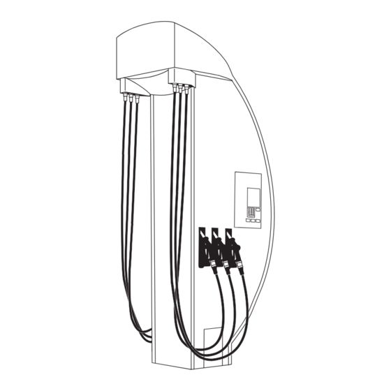
APOLLO 3000L INSTALLATION APOLLO 3000L INSTALLATION The Apollo 3000L dispenser is divided into sections, as follows. 2. Vertical Delivery 4. Apollo 3000L Pipe Assembly Electronics 1. Underground 3. Modules Sump Enclosure Figure 1. Apollo 3000L Components 1.1 Underground Sump Enclosure Installation. -
Page 8: Figure 3. Apollo Underground Sump Front View
• Pack filling material around the sump enclosure approximately up to a point just under the bulkhead fittings; this is to ensure the enclosure does not move while further work is being conducted. 2A03229 APOLLO 3000L Installation and Commissioning Manual Issue 1... -
Page 9: Figure 4. Main Product Feed Line Configuration
• Install the feed line within the sump. The picture below shows the typical feed line assembly. It considers the use of a Tee connector terminated with a ¾” ball valve and a ¾ - ¾” BSP Elbow. These components are not supplied by Gallagher Fuel Systems. Tee connector 3/4”... -
Page 10: Figure 6. Apollo Sump/Column Position Top View
• Backfill and compact to within 150mm of forecourt surface, 30 – 50mm up skirting walls. • Concrete the forecourt as per site requirements. Figure 6. Apollo Sump/Column Position Top View 2A03229 APOLLO 3000L Installation and Commissioning Manual Issue 1... -
Page 11: Vertical Delivery Pipe Assembly Installation
The installation procedure for this module is explained separately for each section, according to the following picture. Delivery A. Vertical B. Head Cabinet Pipe Assembly C. Vent Box Assembly Figure 7. Vertical Delivery Pipes Assembly Components 2A03229 APOLLO 3000L Installation and Commissioning Manual Issue 1... -
Page 12: Figure 8. Vertical Delivery Pipes Assembly Mounting Positions
It must be established as an initial point to start measuring the positions of components and mounting brackets and to obtain mounting heights and ground clearances for final cladding. Figure 8. Vertical Delivery Pipes Assembly Mounting Positions 2A03229 APOLLO 3000L Installation and Commissioning Manual Issue 1... - Page 13 • Repeat process on the rear side. Verify that the brackets on the rear pipe assembly are horizontal with the front set. Also ensure the column stops on rear pipes are positioned exactly in the same relationship from the column as per front set. 2A03229 APOLLO 3000L Installation and Commissioning Manual Issue 1...
-
Page 14: Figure 9. Delivery Pipes Assembly Part Numbers
APOLLO 3000L INSTALLATION Figure 9. Delivery Pipes Assembly Part Numbers 2A03229 APOLLO 3000L Installation and Commissioning Manual Issue 1... -
Page 15: Figure 10. Head Cabinet Mounting Brackets
(see Figure 8). • Attach the Multiplexer board to the underside of the head cabinet assembly (studs are pre-positioned). • Fit VR equipment as per Section 2. Figure 10. Head Cabinet Mounting Brackets 2A03229 APOLLO 3000L Installation and Commissioning Manual Issue 1... -
Page 16: Figure 11. Vent Box Position And Sealing Specifications
Note: Ensure the inside of the vent box assembly is sealed sufficiently to eliminate the potential to leak out into the inside of the dispenser cladding. Figure 11. Vent Box Position and Sealing Specifications 2A03229 APOLLO 3000L Installation and Commissioning Manual Issue 1... -
Page 17: Figure 12. Safety Hose Position
2 for instructions on the installation of coaxial hoses. The hoses have different lengths according to their position, as shown in Figure 13. (Shortest (Longest hose) hose) Figure 13. External Hose Positions 2A03229 APOLLO 3000L Installation and Commissioning Manual Issue 1... -
Page 18: Module Installation
Column End Manifold delivery Ex e enclosure Meter delivery pipe assembly 2A100327 pipe assembly 8A89792 8A89626 Solenoid valve Module frame 2A52536BF assembly 8A89626 REAR Figure 14. Apollo Sump and Modules Assembly 2A03229 APOLLO 3000L Installation and Commissioning Manual Issue 1... -
Page 19: Figure 15. Product Delivery Hoses Connection
Install module C. Fit the hinge pin then lift above the sump and brace to hold the module in place. • Attach feed and delivery hoses to the meter module. • Repeat the last two steps for modules B and A. 2A03229 APOLLO 3000L Installation and Commissioning Manual Issue 1... -
Page 20: Figure 17. Solenoid Valves Cable Distribution
Run the 18 core cable through the cable duct up to the bottom of the head cabinet. • Run the encoder cables through the cable duct to the Multiplexer board located under the head cabinet. 2A03229 APOLLO 3000L Installation and Commissioning Manual Issue 1... -
Page 21: Apollo 3000L Electronics Installation
Central Controller Unit Comms User User Stack Controller Motor Drive Connector Interface Interface Block Bürkert AC Solenoid Vaporix Valve Drive Controller Vaporix Controller VR2 Controllers Multiplexer Figure 19. Apollo 3000L Electronic Set 2A03229 APOLLO 3000L Installation and Commissioning Manual Issue 1... -
Page 22: Figure 20. Setting Of Protocol Jumpers For Pec And Gilbarco Protocols
Connect the Comms cables to the Comms Connector Block according to the following diagram. Communications 2 Wire Pump Comms Vapour Recovery dA dB SP SN 2 3 4 5 Figure 21. Comms Connections 2A03229 APOLLO 3000L Installation and Commissioning Manual Issue 1... -
Page 23: Figure 22. Motor Drive Module Connection Guide
(see Figure 23). Each valve cable has a number that has to match the number on the module. Figure 23. Solenoid Valves Connection Guide 2A03229 APOLLO 3000L Installation and Commissioning Manual Issue 1... -
Page 24: Figure 24. Multiplexer Module Connection Guide
Fit the protective covers once the commissioning process has finished. • External cladding can be fitted now. Refer to Section 2 for instructions on the wiring of VR proportional valve cables and Fafnir vapour sensor cables. 2A03229 APOLLO 3000L Installation and Commissioning Manual Issue 1... -
Page 25: Apollo 3000L Vr2 Components Installation
M4, M6 open spanners and sockets • Standard tools - Posi-drive screwdrivers and metric hex keys • Drills: hand and battery - 3mm, 5mm, 6mm and 20mm bits • Thread tape 2A03229 APOLLO 3000L Installation and Commissioning Manual Issue 1... -
Page 26: Figure 25. Internal Comparison Of Apollo 3000L Standard And Vr2
APOLLO 3000L VR2 COMPONENTS INSTALLATION 2.1.4 VR2 Components The VR2 Apollo 3000L differs from the non-VR2 version in the following key areas: • Extra electronic components inside the Head Cabinet; • VR2 nozzles; • VR2 coaxial hoses and adaptors with supplementary brackets;... -
Page 27: Figure 26. Vr2 Nozzles
(see Figure 27). The vapour is taken from the adaptors via a manifold and return hoses to the vapour sensor/meter assemblies. Figure 26. VR2 Nozzles Figure 27. Coaxial Adaptor 2A03229 APOLLO 3000L Installation and Commissioning Manual Issue 1... -
Page 28: Hydraulic Installation
Drill holes and fit bracket and backing plate using capscrews; backing plate soffit panel cap screws splitter bracket viewed from above Figure 29. Fitting of Bracket and Backing Plate to Soffit Panel 2A03229 APOLLO 3000L Installation and Commissioning Manual Issue 1... -
Page 29: Figure 30. Soffit Panel, Splitter Bracket And Hoses In Place
Figure 30. Soffit Panel, Splitter Bracket and Hoses in Place Fit the splitter bracket covers. Figure 31. Splitter Bracket Cover in Place 2A03229 APOLLO 3000L Installation and Commissioning Manual Issue 1... -
Page 30: Vapour Sensor Assembly
Ensure there is a space between the ferrule on the rear of the vapour sensor and the bottom of the bracket (see arrow); Secure all four clamps, ensuring the sides of each clamp are tightened evenly; 2A03229 APOLLO 3000L Installation and Commissioning Manual Issue 1... - Page 31 Fit each hose over the brass fitting of the chromed gooseneck pipes and secure; Cover the join with 15cm of self-vulcanising tape, stretching it to approximately two thirds its width as it is applied. 2A03229 APOLLO 3000L Installation and Commissioning Manual Issue 1...
- Page 32 Cover the join with 15cm of self-vulcanising tape, stretching it to approximately two thirds its width as it is applied; Adjust the length of the bottom hose, refit connection and seal with tape. 2A03229 APOLLO 3000L Installation and Commissioning Manual Issue 1...
-
Page 33: Figure 32. Complete Vapour Sensor Assembly
The lower manifold has flametraps in the elbows which must not be altered or removed while the VR2 system is operational connection for ball- valve or similar Figure 32. Complete Vapour Sensor Assembly 2A03229 APOLLO 3000L Installation and Commissioning Manual Issue 1... -
Page 34: Connecting To The Underground Return Pipework
Gallagher Fuel Systems recommends that the vapour return lines be connected via a ball-valve or other suitable isolating device, as shown in the illustration below. -
Page 35: Electrical Installation
Cables A and B have to be wired into their terminals as shown in Figure 35. Cable Colour Terminal Brown Ventil 1 + Front Blue Ventil 1 - Brown Ventil 2 + Rear Blue Ventil 2 - Figure 35. Connections into the Bürkert Valve Controller 2A03229 APOLLO 3000L Installation and Commissioning Manual Issue 1... -
Page 36: Figure 36. Phoenix Connector For Vapour Sensor Cables
Once wired, the Phoenix Connectors have to be plugged into the Vaporix Control unit taking note of A (front) and B (rear) positions. Figure 37. Phoenix Connectors on the Fafnir Unit 2A03229 APOLLO 3000L Installation and Commissioning Manual Issue 1... -
Page 37: Apollo 3000L Commissioning
The dispenser is supplied with an specific configuration loaded onto the SD card on the Central Controller Module. However, following the physical installation of the dispenser, the system must be configured via the Service Mode prior to use. 2A03229 APOLLO 3000L Installation and Commissioning Manual Issue 1... -
Page 38: Figure 38. Service Mode Function Screens
Service Mode Function Screens 3.2.3 SD Card Setting The SD Card can be set to ACTIVE or LOCKED by pressing the 5 key. Only remove an SD Card when in the LOCKED mode. 2A03229 APOLLO 3000L Installation and Commissioning Manual Issue 1... - Page 39 Note that the update request may be queued and may not be actioned for some minutes, depending on the number and nature of other queued requests. Ensure every module’s firmware is updated. 2A03229 APOLLO 3000L Installation and Commissioning Manual Issue 1...
- Page 40 3.2.7 Setting a Password This function allows the password for the Service Mode to be changed. Once set, if the password is forgotten, Gallagher will only be able to reset to default when provided with the serial number of the Central Controller module.
- Page 41 The errors are displayed for each fuel point. The dispenser logs all errors to the SD Card (even those that have been cleared) in a form that is not easily read. Gallagher Technical Support can interpret dispenser logs and provide a more detailed description of errors.
- Page 42 5 Digit mode ( 1 ) or 6 Digit mode ( 0 ). Each fuel point (side) must be set. After making this change, the dispenser must be repowered. 2A03229 APOLLO 3000L Installation and Commissioning Manual Issue 1...
- Page 43 The dispenser leaves the factory with a default price of 999.9 CPL (cents per litre). The presence of any other price indicates either the grade price has been manually set or a price has been received from the POS. 2A03229 APOLLO 3000L Installation and Commissioning Manual Issue 1...
- Page 44 1% increments using the keys 4 (+) and 6 (-) Press 5 to store the setting - 5% Press the f key to scroll through and set the available grades in the dispenser. 2A03229 APOLLO 3000L Installation and Commissioning Manual Issue 1...
- Page 45 For use when VR2 equipment is installed. 10 indicates the system is working correctly. 00, 01 or 11 indicates a fault. Pressing the C key exits the stack test and turns all valves off. 2A03229 APOLLO 3000L Installation and Commissioning Manual Issue 1...
- Page 46 Press 6 to move to TIME and set in the same manner. Gallagher advise the checking of the date and time when obtaining dispenser logs. Should either be incorrect, make a note to be included with the logs. This will assist in finding the events being investigated.
-
Page 47: Tatsuno Meter Calibration
When a Flow Meter delivers LESS fuel than required the display will show an amount greater than the actual delivery. Solution: “INCREASE” the amount delivered per revolution by moving the calibration wheel in an anti-clockwise direction. 2A03229 APOLLO 3000L Installation and Commissioning Manual Issue 1...
Need help?
Do you have a question about the APOLLO 3000L and is the answer not in the manual?
Questions and answers