
Related Manuals for Brivis BX3 Series


Summary of Contents for Brivis BX3 Series
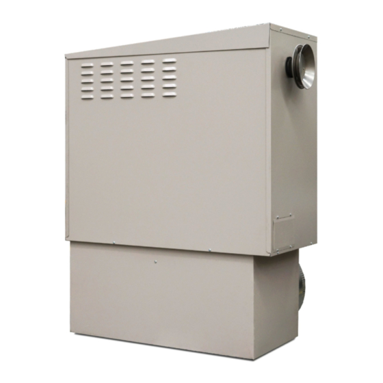
- Page 1 Brivis Classic Ducted Gas Heater Installer’s Manual BX3 Series 2PWN Series UF3 & DF3 Series PLEASE READ THESE INSTRUCTIONS CAREFULLY BEFORE INSTALLING THIS PRODUCT...
-
Page 2: Safety Warnings
Scope This Installer's Manual is intended to be used as a guideline for the installation of Brivis Gas Fired Central Heaters. It covers only the installation and commissioning of the heater and the allowable flue configurations. Although minimum recommended return air grilles and allowable duct outlet quantities are specified, it does not cover the actual ducting design required to suit the installation. -
Page 3: Table Of Contents
8.0 Outlet Guide ..............................14 9.0 Thermostat Installation ............................15 9.1 Wiring the Manual or Programmable Thermostat (HEATING ONLY) ............16 9.2 Wiring the Brivis Programmable Thermostat (ADD-ON & FAN ONLY) ............17 10.0 Commissioning and Control Settings ......................18 10.1 Commissioning Instructions......................... 18 10.2 Start &... -
Page 4: General Guidelines
1.0 General Guidelines Brivis Classic heaters are designed to provide a central source of heat for a ducted central heating system. Brivis Classic heaters should not be installed downstream from an air washer, an evaporative cooler or refrigerative cooling system. Nor are they designed to be installed on a marine craft, houseboat, or any similar environment. -
Page 5: Electrical Power Supply
Install the heater in a position that allows adequate and safe access for service as per guidelines in this manual and its applicable standards. Otherwise, the cost of any equipment and additional labour involved in accessing such heater installations will not be accepted by Brivis. 1.8 Installation of External Heaters The Classic BX3 range is designed to be installed outside of the house only. -
Page 6: Installation Of Internal Heaters In A Room, Enclosure, Residential Garage Or Plant Room
Installing Beneath the Floor • There must be a minimum clearance of 200mm between any part of the appliance and the lowest part of the floor structure. In addition to this, refer to section "Service Clearances”. • The heater must be located within 2m of the access opening, or there is to be a minimum clearance of 1.2m between the lowest part of the floor structure and ground level, maintained from the access opening to the heater. -
Page 7: Classic Bx3 Model Guidelines
2.0 Classic BX3 Model Guidelines 2.1 Heater Dimensions Diagram 1. HEATER ø ø Table 1: BX3 unit dimensions Dimension BX315 BX320 BX326 [mm] 1028 1145 1145 1280 1085 1085 1220 Base Box øSa øRa... -
Page 8: Service Clearances
2.2 Service Clearances Front A minimum of 500mm must be provided at the side facing away from the house. A minimum of 300mm must be provided at each end of the heater. A minimum of 1000mm must be provided above the heater roof. This clearance must be maintained for the entire surface area of the heater roof. -
Page 9: Orientation Of Flue Terminal
2.4 Orientation of Flue Terminal The flue terminal for BX3 models is supplied and fitted to the heater as shown in Diagram 2. The flue terminal must be orientated correctly to ensure flue gases are expelled away from the building wall as shown. -
Page 10: Area To Cut In The Wall
2.5 Area to cut in the wall When installing the heater at ground level, create one rectangular hole to suit the total pop width and height, all the way to ground level, refer Diagram 3. Diagram 3. WALL CUT OUT AREA CONCRETE BASE GROUND... -
Page 11: Classic 2Pwn Model Guidelines
3.0 Classic 2PWN Model Guidelines 3.1 Heater Dimensions 2PWN15, 2PWN20 & 2PWN20 XA Diagram 4. øN øSa øRa Table 2: 2PWN 15, 20 & 20XA unit dimensions Dimension [mm] Model øN øRa øSa 2PWN15 704 1147 723 115 1187 2PWN20 704 1147 723 115 1187... -
Page 12: Heater Dimensions 2Pwn26 & 2Pwn26 Xa
263 269 813 791 1266 125 3.3 Service Clearances Brivis internal heaters installed within the roof space shall be installed on a platform with minimum “Service Clearances” provided as detailed in Diagram 6. For more information regarding platform requirements refer to Section 1.9 “Installation of Internal Heaters”. -
Page 13: Splitting Classic 2Pwn Heaters
3.4 Splitting Classic 2PWN Heaters The Classic 2PWN model heaters can be split in two to allow for ease of installation. To split the heater, follow these simple instructions: • Remove the access panel located on top of the fan cabinet compartment by removing the two screws. •... -
Page 14: Installation Alternatives For All Df3 & Uf3 Models
4.2 Installation alternatives for all DF3 & UF3 models All UF3 and DF3 models can be installed on a base box with a left hand pop, right hand pop, or front pop as shown in Diagram 8. Diagram 8. UF3 & DF3 base box airflow direction options Downflow - DF3 Upflow - UF3 4.3 Service Clearances... -
Page 15: Internal Flueing Instructions
• Require a 100 mm round single or twin wall non-corrosive metal flue, and shall be terminated with an approved 100mm round metal flue cowl. The Brivis Remote Flue terminal (part number B018384) may be used to terminate the flue on the outside wall of the building, typically under floor installations. -
Page 16: Fan Speed Setting
• 7.0 Ducting Information Good duct design and sizing are essential to every Brivis Central Heating system. Use the Brivis "SuperSizeGuide"/Brivisize™ and technical data within this manual for the best results and follow these guidelines: • Ductwork should be well insulated, airtight and have a minimum insulation rating of R1.O (R1.5 in some areas). -
Page 17: Outlet Guide
8.0 Outlet Guide The outlet chart provides recommendations based on using the Brivis "SuperSizeGuide" / Brivisize™ or a system designed using accepted design principles. These figures also relate to typical size registers and diffusers used on domestic heating systems i.e. 300mm x 100mm floor registers and 150mm round ceiling diffusers, with 150mm ductwork connection. -
Page 18: Thermostat Installation
Note: The maximum and minimum number of outlets detailed in Table 5 are as per AGA specification. 9.0 Thermostat Installation All Brivis heating systems can be controlled by various Brivis Thermostats, each explained in detail below. A Thermostat inside the house is wired to the control module in the heater. The Thermostat monitors the temperature in the house and switches the system ON and OFF in order to maintain a set temperature. -
Page 19: Wiring The Manual Or Programmable Thermostat (Heating Only)
Brivis Manual and Brivis Programmable Thermostats can be wired directly to a Classic heater for heating only applications. Note: Only use Brivis Thermostats, as any failure relating to a non-Brivis Thermostat will not be covered under warranty. To connect the Thermostat to the unit: Run twin core cable no less than 0.75mm²... -
Page 20: Wiring The Brivis Programmable Thermostat (Add-On & Fan Only)
Field Supplied Wires For Brivis Classic 2PWN units the ‘Fan speed terminal block’ is inside the fan housing. The RED wire from the heater PCB extends to the ‘Fan speed terminal block’ with a BROWN wire quick connect fitting. This BROWN wire shall be joined to the RED wire supplied with ADD-ON relay, i.e. -
Page 21: Commissioning And Control Settings
• All these steps must be carried out by a qualified tradesperson • If the heater cannot be adjusted to operate in accordance with these instructions, then contact the Brivis Customer Service Centre (contact details are on the back cover of this manual) 10.1 Commissioning Instructions... -
Page 22: Setting The Fan Speed
• Issue any required documentation to the relevant people/authorities in regards to the installation of the heater, the gas connection and power supply (for example, a Certificate of Compliance and Certificate of Electrical Safety). Note: Product warranty registration forms can be found online at brivis.com.au or in the owner’s manual. -
Page 23: Technical Specifications
1035 1004 66.5 2PWN26 XA Downflow / Upflow Models 17.9 0.28 0.35 DF320 XA 17.6 0.25 0.31 UF320 XA 28.6 0.36 0.44 UF326 XA **Model and (Base Box Pop) size Note: Brivis reserves the right to change specifications without notice. - Page 24 © Brivis Climate Systems Pty. Ltd. 2016. All rights reserved. No part of these documents may be used in any way or form without prior written consent from Brivis Climate Systems Pty Ltd. Part Number: B062448 May 2016...
Need help?
Do you have a question about the BX3 Series and is the answer not in the manual?
Questions and answers