Lennox ComfortSense 3000 Series Operation Manual
C0stat05ff1l
Hide thumbs
Also See for ComfortSense 3000 Series:
- Operation manual (10 pages) ,
- Brochure (2 pages) ,
- Installation instructions manual (6 pages)
Table of Contents
Advertisement
E2017 Lennox Industries Inc.
Dallas, Texas, USA
THIS MANUAL MUST BE LEFT WITH THE OWNER
FOR FUTURE REFERENCE
WARNING
Improper installation, adjustment, alteration, service or
maintenance can cause property damage, personal injury
or loss of life. Installation and service must be performed
by a qualified installer, service agency or the gas supplier
OPERATION MANUAL
C0STAT05FF1L CS3000
Commercial Programmable
CONTROLS
507518-02
5/2017
Supersedes 507518-01
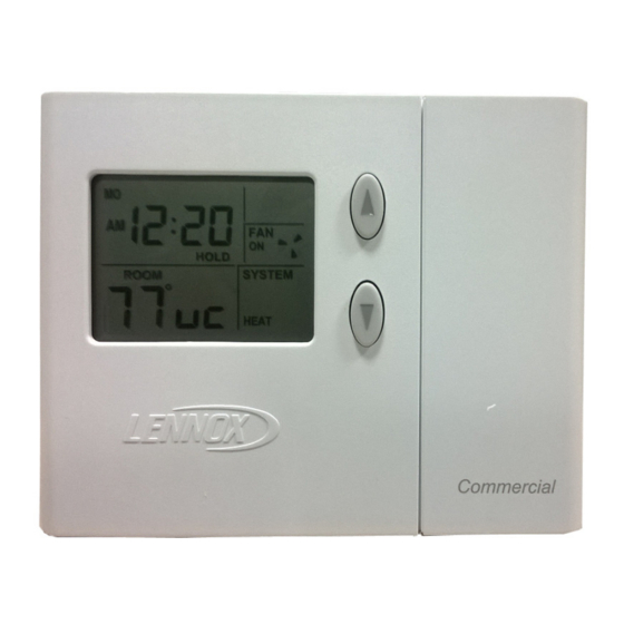
C0STAT05FF1L 5/2 Day Programmable
Thermostat
The Lennox ComfortSense
Programmable
Thermostat,
(11Y05) is a 5/2 day programmable and 2-heat / 2-cool
electronic thermostat. It includes a programmable filter
change reminder, an equipment maintenance reminder,
and a system check indicator to notify the user when the
equipment requires service.
This thermostat is suitable for 2‐stage heat / 2‐stage cool
applications using a gas or electric auxiliary heat source and
can also be used with an economizer.
Thermostat
®
3000 Series Commercial
Model
C0STAT05FF1L
Advertisement
Table of Contents

Subscribe to Our Youtube Channel
Related Manuals for Lennox ComfortSense 3000 Series


Summary of Contents for Lennox ComfortSense 3000 Series
-
Page 1: 5/2 Day Programmable Thermostat
OPERATION MANUAL C0STAT05FF1L CS3000 E2017 Lennox Industries Inc. Dallas, Texas, USA Commercial Programmable Thermostat CONTROLS 507518-02 5/2017 Supersedes 507518-01 C0STAT05FF1L 5/2 Day Programmable Thermostat ® The Lennox ComfortSense 3000 Series Commercial Programmable Thermostat, Model C0STAT05FF1L THIS MANUAL MUST BE LEFT WITH THE OWNER... -
Page 2: Table Of Contents
The remote indoor sensor when connected and configured General will act as a room temperature sensor instead of internal temperature sensor available with the thermostat. The dip These instructions are intended as a general guide and do switch is used to select either built-in or external remote not supersede local codes in any way. -
Page 3: Buttons, Backlight, Timers & Settings
At this point, the thermostat will be fully functional; its default IMPORTANT temperature set point (not shown) is 70°F. At this point, if the equipment has been fully powered and if a heat demand Do NOT begin pressing buttons until after you read the fol were present, the system would begin operating. -
Page 4: Day/Time - Set Day And Time
DAY/TIME - Setting the Day and Time Heat Cool Press the DAY/TIME button and set the CURRENT hour, 5:30 minute, and day of week as follows: Prog Day/Time 1. “ 12” will flash on the screen. Press the up or down HOLD AUTO arrows buttons to change the hour. -
Page 5: Cool - Cool Mode
Heating Demand COOL - Using the Cool Mode The thermostat must be in heat mode in order to properly control the heating equipment. In heat mode, when the Enabling and Disabling Cool Mode actual temperature is lower than the temperature set point Use the COOL button to enable or disable cool mode as the thermostat detects a heating demand and activates the desired. -
Page 6: Hold - Temperature Hold Mode
If the thermostat is in cool mode, pressing the COOL button disappear. This indicates that the cooling demand has been disables COOL mode (indicated by OFF in the SYSTEM satisfied and that the cooling equipment has been turned box - see figure 6). off. -
Page 7: Prog - Thermostat Programming
occupancy mode. Each button press adjusts the setpoint up arrow buttons until the desired set point is displayed; or down by 1 degree. “HOLD” flashes (see figure 9). This overrides the program for 2 hours from the last button press, then returns to the Heat Cool program. - Page 8 heat and cool) for five consecutive days using a set of four allows less heating while the location is NOT occupied; D unique events per day. The remaining two days can then be reflects a cooler sleeping temperature. The 2-day bar graph set for a different set of four unique events per day.
-
Page 9: Fan - Controlling Fan Operation
5. Use the up or down arrow buttons to select either uc Heat Cool 10:10 (unoccupied) or oc (occupied) minute; press PROG. 6. Use the up or down arrow buttons to select the desired Day/Time Prog PROG temperature set point; press PROG. SYSTEM ROOM °... -
Page 10: Settings - Filter And Maintenance Reminders
Table 1. Filter and Maintenance Reminders SETTINGS - Filter/Maintenance Reminders Buttons to Available Settings and How Reminder to Use The thermostat is designed to remind you when the filter needs changing or when routine maintenance is required, Settings Total fan run time expressed in FILTER as (and if) defined, by you. -
Page 11: Settings - Balance Point
remote indoor temperature sensor used for temperature MAINT TU WE TH FR SA SU control. FILTER 10:i2 Occupied and Unoccupied Modes SERVICE During permanent hold mode the occupancy output follows the program. During two hour hold mode the user can change the occupancy status by pressing the enter button. -
Page 12: Service Indicator
programmed. Such an instance can occur as a result of a Service Indicator power surge or similar electrical disturbance (e.g. after an electrical storm or power outage). The RESET button can When abnormal equipment operation is detected, the be used to recover from this situation. SERVICE indicator will flash on the screen (see figure 16). -
Page 13: Removing/Installing Thermostat
below the SETTINGS button (see figure 17). Use a paper Technical Specifications clip or small pencil to press the RESET button; ALL Thermostat Type thermostat settings will be reset to the defaults listed in the Electronic programmable thermostat for non-heat pump, Default Thermostat Settings section. - Page 14 Setting Temperature Scale Temperature Measurement Range Measurement Scale: Fahrenheit To select either Fahrenheit or Celsius, press Settings button three times. Press up/down arrows to toggle Measurement Range: 35°F to 99°F between Fahrenheit and Celsius. Once selected, press Measurement Resolution: 0.125°F Settings button to exit.
- Page 15 Table 4. Terminal Designations Minimum cycle time (applies to both furnace cycle and elapsed time) between any furnace activation and the next Terminal Description furnace activation): 6 minutes. 24VAC Minimum elapsed time between any compressor activation Compressor Stage 1 cooling and the next compressor activation: 6 minutes.
- Page 16 Service Reminder IMPORTANT The SERVICE indicator is displayed only under the following conditions: Power must be applied for at least six consecutive hours if the thermostat Y1 terminal has been activated with prior to a power loss in order for memory to be retained for 24VAC for at least 5 minutes, AND the L terminal is the specified time.
Need help?
Do you have a question about the ComfortSense 3000 Series and is the answer not in the manual?
Questions and answers