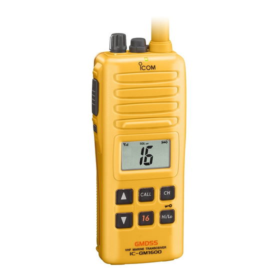
Icom IC-GM1600 Instruction Manual
Survival craft 2-way radio
Hide thumbs
Also See for IC-GM1600:
- Instruction manual (32 pages) ,
- Service manual (34 pages) ,
- Instruction manual (32 pages)

Related Manuals for Icom IC-GM1600


Summary of Contents for Icom IC-GM1600
- Page 1 INSTRUCTION MANUAL SURVIVAL CRAFT 2-WAY RADIO iGM1600 This device complies with Part 15 of the FCC Rules. Operation is subject to the condition that this device does not cause harmful interference.
-
Page 2: Safety Training Information
Electromagnetic Fields. • ALWAYS keep the antenna at least 2.5 cm (1 inch) away from the body when transmitting and only use the Icom belt-clips which are listed on • American National Standards Institute (C95.1-1992), IEEE Standard for page 23 when attaching the radio to your belt, etc., to ensure FCC RF Safety Levels with Respect to Human Exposure to Radio Frequency exposure compliance requirements are not exceeded. -
Page 3: Information En Matière De Sécurité
RF sans fil; attache pour ceinture (MB-86, MP- 103Y), bloc-piles rechargeable au lithium-ion (BP-252). Interférence électromagnétique et compatibilité En mode de transmission, votre radio Icom produit de l'énergie de RF qui peut CAUTION provoquer des interférences avec d'autres appareils ou systèmes. Pour éviter Afin de vous assurer que votre exposition à... -
Page 4: Recommendation
RECOMMENDATION PREFACE CLEAN THE TRANSCEIVER THOROUGHLY WITH FRESH Thank you for choosing this Icom product. The IC-GM1600 WATER after exposure to saltwater, and dry it before operat- is designed and built with Icom’ s survival craft way radio ing. Otherwise, the transceiver's keys, switches and control- state of the art technology and craftsmanship. -
Page 5: Important
• Force majeure, including, but not limited to, fires, earth- quakes, storms, floods, lightning, other natural disasters, disturbances, riots, war, or radioactive contamination. • The use of Icom transceivers with any equipment that is not manufactured or approved by Icom. -
Page 6: Precaution
Confirm that the antenna and battery pack are dry before attaching. Exposing the inside of Icom, Icom Inc. and Icom logo are registered trademarks of Icom Incorporated the transceiver to dust or water can cause serious damage (Japan) in the United States, the United Kingdom, Germany, France, Spain, to the transceiver. -
Page 7: Fcc Information
CAUTION: Changes or modifications to this transceiver, not expressly approved by Icom Inc., could void your authority to operate this transceiver under FCC regulations. -
Page 8: Table Of Contents
TABLE OF CONTENTS SAFETY TRAINING INFORMATION ..........i 5 SET MODE ������������������������������������������������������������������������ 11–15 INFORMATION EN MATIÈRE DE SÉCURITÉ ....... ii ■ SET mode settings ............... 11 RECOMMENDATION ..............iii ■ SET mode items ..............12 PREFACE ..................iii 6 BP-234 BATTERY PACK ��������������������������������������������������������� 16 IMPORTANT .................. -
Page 9: Operating Rules
OPERATING RULES D Priorities (2) OPERATOR’S LICENSE • Read all rules and regulations pertaining to priorities and A restricted Radiotelephone Operator Permit is the license keep an up-to-date copy handy. Safety and distress calls most often held by small vessel radio operators when a radio take priority over all others. -
Page 10: Supplied Accessories And Attachments
SUPPLIED ACCESSORIES AND ATTACHMENTS ■ Supplied accessories ■ Attachments D Neckstrap The following accessories are supplied: Qty. q Neckstrap........1 Pass the neckstrap through the w Battery charger (BC-173). -
Page 11: Supplied Accessories And Attachments
To attach the battery pack: When attaching or removing a battery pack, make sure Insert the battery pack into the IC-GM1600 completely, then the rubber seal is set in the groove of the battery pack turn the lock screw clockwise. -
Page 12: Panel Description
PANEL DESCRIPTION ■ Front, top and side panels q VOLUME CONTROL [VOL] Turns power ON and adjusts the audio level. w MICROPHONE CONNECTOR [MIC/SP] Connects an optional external microphone. NOTE: Attach the jack cover when the optional speaker microphone is not used. Otherwise, water may get into the transceiver. - Page 13 PANEL DESCRIPTION i CHANNEL 16 KEY [16] Push to select Channel 16. (p. 7) o CHANNEL UP/DOWN KEYS [Y]/[Z] ➥ Selects an operating channel. (pgs. 7, 8) ➥ Selects an item in the SET mode. (p. 11) ➥ In the SET mode, while holding down [SQL], push to select an option for the item.
-
Page 14: Function Display
PANEL DESCRIPTION ■ Function display t BATTERY INDICATOR Displays the battery's remaining power. Using rechargeable battery pack Indication Charging Battery Battery level Full required exhausted blinks when the battery is overcharged. Using BP-234 battery pack Indication Battery Battery Battery level Full replacement q SIGNAL STRENGTH INDICATOR (pgs. -
Page 15: Basic Operation
BASIC OPERATION ■ Channel selection D Call channel D Channel 16 The Call channels can be re-entered (p. 9) and may be used Channel 16 is the distress and safety channel. It is used to to store your most often used channels for quick recall. establish the initial contact with a station and, for emergency communications. -
Page 16: Receiving And Transmitting
BASIC OPERATION ■ Receiving and transmitting q Rotate [VOL] clockwise to turn ON the transceiver power. IMPORTANT: To maximize the readability of your transmit- w Adjust the volume and squelch level. ted signal, pause for a second after pushing [PTT] and ➥... -
Page 17: Call Channel Entry
BASIC OPERATION ■ Call channel entry ■ Adjusting the squelch level Squelch enables the audio to be heard only while receiving The Call channel switch is used to select Channel 9* by de- a signal that is stronger than the set level. A higher level fault, however, you can set your most often-used channel for blocks weak signals, which enables you to receive only a quick recall. -
Page 18: Lock Function
BASIC OPERATION ■ Lock function ■ Monitor function The Monitor function temporarily cancels the Squelch func- The Lock function electronically locks all keys (except for tion to check for weak signals. See page 12 for details of the [PTT], [SQL• ] and [Hi/Lo•... -
Page 19: Set Mode
SET MODE ■ SET mode settings D SET mode operation The SET mode is used to change 11 transceiver functions: Beep Tone function, monitor switch action, Backlight func- q Turn OFF the transceiver power. tion, LCD contrast selection, Auto Power Save function, Self w While holding down [SQL•... -
Page 20: Set Mode Items
SET MODE ■ SET mode items D Beep tone function “bP” D Backlight function “bL” You can select silent operation by turning the beep tones This function is convenient for nighttime operation. The back- OFF, or you can have 2 types of confirmation beeps sound light brightness can be adjusted between OFF, 1 (dark)–3 at the push of a key. - Page 21 SET MODE D Auto power save function “PS” D Self check function “SC” The Auto Power Save function reduces the battery drain by The Self Check function checks various transceiver status deactivating the receiver circuit for preset intervals. by itself, and informs you if a problem is found. The self •...
- Page 22 SET MODE D Battery voltage indicator “bt” D Squelch sensitivity function “SS” Select whether or not to display the voltage of the battery on When this function is turned ON, blocking against the noise the LCD at power ON. is improved. Therefore the squelch is not easily affected by •...
-
Page 23: Set Mode
SET MODE SET MODE LIST Function Indication Setting Beep Tone function “bP” OFF/ON*/US Monitor switch action “Sq” PUSH*/HOLD Backlight function “bL” OFF/1/2/3* LCD contrast selection “LC” 1/2/3*/4 Auto Power Save function “PS” OFF/ON* Self Check function “SC” OFF*/ON Battery voltage indicator “bt”... -
Page 24: Bp-234 Battery Pack
BP-234 BATTERY PACK The optional BP-234 battery pack is a non-rechargeable, DO NOT • apply excessive pressure to the battery. This may result Lithium battery pack for operation in a survival craft. The fol- in electrolyte leakage, possibly causing an explosion. lowing precaution must be observed. -
Page 25: Battery Charging (For Only On-Board Use)
If any of these conditions RDANGER! NEVER strike or otherwise impact the battery. Do not occur, contact your Icom dealer or distributor. use the battery if it has been severely impacted or dropped, RWARNING! NEVER put the batter y in a microwave oven, or if the battery has been subjected to heavy pressure. -
Page 26: Battery Charging (For Only On-Board Use)
The charger is not waterproof. CAUTION: DO NOT charge the battery outside of the specific tem- perature range: +10˚C to +40˚C (+50°F to +104°F). Icom recom- *Differs depending on version. mends charging the battery at +20˚C. The battery may heat up or rupture if charged out of the specific temperature range. -
Page 27: Optional Swivel Belt Clip
OPTIONAL SWIVEL BELT CLIP ■ MB-86 contents e Once the transceiver is locked in place, it swivels. Qty. Belt clip ........1 Base clip . -
Page 28: Channel List For Survival Operation
CHANNEL LIST FOR SURVIVAL OPERATION Channel number TX/RX Channel number TX/RX Channel number TX/RX 156.300 MHz 156.400 MHz 156.450 MHz 156.500 MHz 156.550 MHz 156.600 MHz 156.650 MHz 156.700 MHz 156.750 MHz 156.800 MHz 156.850 MHz 156.375 MHz 156.425 MHz 156.475 MHz 156.575 MHz 156.625 MHz... -
Page 29: Troubleshooting
TROUBLESHOOTING PROBLEM POSSIBLE CAUSE SOLUTION REF� The transceiver does • The battery is exhausted. • Change to a new battery pack (Survival). p. 16 not turn ON. • Recharge the battery pack (On-board). pp. 17, 18 • The Battery pack is not correctly attached. •... -
Page 30: Specifications
SPECIFICATIONS D GENERAL D RECEIVER • Receive system: Double-conversion • Frequency coverage (TX/RX): 156.300–156.875 MHz superheterodyne • Mode: 16K0G3E • Sensitivity: • Channel spacing: 25 kHz [USA] (at 12 dB SINAD) 0.25 µV typical • Power supply requirement: Battery packs (BP-234 or BP-252) [GEN] (at 20 dB SINAD) –2 dBµ... -
Page 31: Options
OPTIONS D BATTERY PACKS <FOR SURVIVAL CRAFT USE> • BP-234 lithium battery pack 9.0 V/3300 mAh Lithium battery pack. <FOR ON-BOARD USE> • BP-252 lithium battery pack 7.4 V/980 mAh Li-ion battery pack. D BELT CLIPS • MB-103Y belt clip The same as supplied with the transceiver. - Page 32 A-6383D-1EX-e Printed in Japan 1-1-32 Kamiminami, Hirano-ku, Osaka 547-0003, Japan 2004–2016 Icom Inc. ©...
Need help?
Do you have a question about the IC-GM1600 and is the answer not in the manual?
Questions and answers