Table of Contents
Advertisement
Advertisement
Chapters
Table of Contents

Related Manuals for Sewha SI 410


Summary of Contents for Sewha SI 410
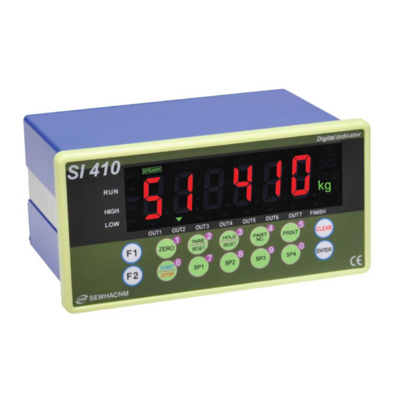
- Page 1 Digital Weighing Indicator SI 410 User Manual Ver 2.0 2017.04.05...
-
Page 2: Table Of Contents
Contents 1. BEFORE INSTALLATION ........................- 3 - 2. INTRODUCTION ..........................- 4 - 2-1. Introduction ................................- 4 - 2-2. Cautions ................................. - 4 - 2-3. Features .................................. - 4 - 3. SPECIFICATION ........................... - 5 - 3-1. Specification ................................. - 5 - 3-2. -
Page 3: Before Installation
Copy Rights 1. All Right and Authority for this Manual is belonged to SEWHA CNM CO., LTD. 2. Any kinds of copy or distribution without permission of SEWHA CNM CO., LTD. will be prohibited. 3. This manual may be changed as the version is upgraded, without previous notice. -
Page 4: Introduction
7. Item’s performance will be up-dated continuously base on previous version’s performance. 2-3. Features 1. SI 410 model is standard size indicator which is easy to install on the panel. 2. Front panel is covered with Polycarbonate film, strong against dust and water. -
Page 5: Specification
3. SPECIFICATION 3-1. Specification Content Specification Display Resolution 1/20,000 Internal Resolution 1/2,000,000 (±1,000,000) Input Sensitivity Min 0.1µV/V Max Signal Input Voltage Max 3.0mV/V Load cell Excitation DC +5V Analog Part A/D Conversion Method Sigma-Delta Decimal Point 0, 0.0, 0.00, 0.000 Offset 10PPM/℃... -
Page 6: Option
3-2. Option Option1 Serial Port (RS-422) Option2 Serial Port (RS-485) Option 3 Serial Port (RS-232) Option 4 ETHERNET CARD Option 5 Analog Output(0~20mA) Option 6 Analog Output(0~10V) Option 7 BCD OUT Option 8 BIN IN Option 9 SD Memory card 3-3. - Page 7 3-3-2. State LED State When the weight is stable, ON. STEADY When the current weight is near zero, ON. ZERO When the “TARE” function is set, ON. TARE HOLD When the “HOLD” function is set, ON. When indicator sends date out through serial communication. When indicator receives date out through serial communication.
- Page 8 3-3-3. Key Operation - Press 4 times within 3secs, to enter to Function setting mode. - Press 4 times within 3secs, to enter to “Hidden function” mode. - Make the weight value to Zero (It doesn’t work under hold state or weight is near zero.) - Enter to function mode in SET-UP mode.
- Page 9 3-3-4. Hot key Double tare setting (Once tare is set, Another tare is overlapped.) Print the Sub-total out Forced discharge Display the current weight during 5 secs. Display the Sub-total weight during 5 secs. Display the Grand-total weight during 5 secs. Print the Grand-total out Input Tare Value(when F530 is set as 01) Delete the Sub-total weight...
-
Page 10: Rear Panel
3-4. Rear Panel (1) AC Power input terminal (2) External input terminal: User selectable 6EA (Function 156~161) (3) Serial Interface terminal Terminal RS – 232 (4) Loadcell Input terminal Terminal EXC+ EXC- SIG+ SIG- SHLD Loadcell EXC+ EXC- SIG+ SIG- SHEILD (5) Relay output terminal: User selectable 7EA (Function 141~147, COM is common) Terminal... -
Page 11: Installation
4. Installation 4-1. External Dimension & Cutting Size 4-2. Installation Components SI 410 User Manual - 11 -... -
Page 12: Load Cell Installation
4-3. Load cell Installation Load Cell Wire Connection (In case of SEWHACNM’s Load cell) It depends on the manufacturer of load cell, please check the specification. Under Set-up the Load cell, if EXC+ and EXC- have a short circuit, It may cause damage in the indicator.(specially analogue board) If you connect other wires to Load cell terminal wrongly, it may cause damage in the analogue board. -
Page 13: Set-Up
5. Set-Up 5-1. Set-up mode 5-1-1. How to enter Set-up mode If “SET-UP” is displayed, it is complete to Press key for 4 times enter the set-up mode. How to enter each set mode SET-UP mode Press key for 4 times Analog value Press key for 4 times ... - Page 14 SP set value Part Number key for saving data.. key for cancel and go back to previous step. - 14 -...
-
Page 15: Test Weight Calibration Mode (Using Test Weight)
5-2. Test Weight Calibration Mode (Using test weight) 5-2-1. Calibration Calibration is the process of adjusting weight balance between "Real Weight" on the Load Cell and "Displayed weight of Indicator". When you replace Load Cell or Indicator, you have to do Calibration process once again. - Page 16 5-2-2. Start Test Weight Calibration Mode Remove “CAL-BOLT” on the Rear panel, When “CALIBR” displays, press key, and press “CAL - LOCK S/W” inside. “ select “WCAL” and press key. 5-2-3. Setting “Capacity of weighing Scale” After displaying “CAPA”, input max capacity with keys & Press key to save &...
- Page 17 5-2-4. Decimal point and division setting After “DIVI” is displayed, locate the decimal point with keys, and set the division with keys. Press key to save. Max decimal point will be 0.001, and digit can be selected among 1, 2, 5, 10, 20, 50.
- Page 18 Indicator will search “DEAE weight” during 10secs automatically to find the best condition. In this step, if there is unstable condition such as some forces or Vibration on the scale part, “Error-A” will be displayed, and “DEAD value” will not be calculated. Please remove the cause of the force or vibration and process it again.
- Page 19 Calculate Span value during 10~20 secs After calculation, span value will be displayed on When “CALEND” is displayed and calibration is completed. the display. Then press key. - 19 -...
-
Page 20: Simulation Calibration Mode (Calibrate Without Test Weight)
5-3. Simulation Calibration Mode (Calibrate without Test weight) With this “Simulation Calibration Mode” you can make simple calibration without any “TEST weight” This calibration mode uses “Load cells’ max capacity” and “Max Output Rate(mV)”, so the weight adjustment degree might be less than “Test weight Calibration”. The guaranteed resolution of this “Simulation Calibration”... - Page 21 5-3-2. Setting “Capacity of Load Cell” After “CAPA” displayed, Check Max Capacity of Load cell, Input the Max Capacity of Load cell. (refer the load cell label, or Test Report.) And press key. In case of multiple pieces of load cells are installed, Please make sum of each load cell’s capacity and make setting with Max Capacity.
- Page 22 5-3-4. Measuring the “DEAD” Weight of Weighing Scale When “DEAD” displays, Press key, then indicator will calculate dead weight of scale part automatically (While this process, there should be nothing on the scale part.) 5-3-5. Inputting Max Output (Rated Output Voltage / mV) After is displayed, Check the Rated output value of Load cell.
- Page 23 If input wrong value, there will display “Err-01”, please go back to Setting “Capacity of Load Cell”. After recheck the label of load cell and retry the process. Calculated span value will be displayed. Then press key to finish the calibration step.
-
Page 24: F-Function Setting
5-4. F-FUNCTION Setting F-FUNCTION Setting 5-4-1. When is displayed, press Press key 4 times “SETUP” key. Function No. Set value Function No. ↑ or input the function No. by number key (0~9). After select “Function No.” area by pressing key. - Page 25 5-4-2. F-Function List F-list Subject Contents Equipment No. setting (ID No.) 01~99 Weight–Back up Mode 00:Normal mode 01: Weight Back up Mode(Zero) 02: Weight Back up Mode(Zero&Tare) Weighing Data Save Method 00: Manual: Whenever “Print” key input 01: Auto: At every steady states 02: Auto: At the first steady states 04: Manual&Auto: At every steady states 05:Manual&Auto: At the first steady states...
- Page 26 Paper Withdraw Rate setting 00 ~ 09 (Unit : 1line add) (After Continuous/Single Print) Paper Withdraw Rate setting 00 ~ 09 (Unit : 1line add) (After SUB/Grand-total Print) Sub-total date delete after Sub- 00 : No delete total printing 01 : Delete Grand-total date delete after 00 : No delete Grand-total printing...
- Page 27 Relay Output 5 Contact 00 : A Dry contact 01 : B Dry contact Relay Output 6 Contact Relay Output 7 Contact 00 : Disuse 07 : Hold / Hold Reset External Input 1 Setting 01 : Zero 08 : Run External Input 2 Setting 02 : Tare 09 : Stop...
- Page 28 Port 1 transference under 00 : Countinuously stream mode 01 : Single time on every steady state 02 : Single time at the first steady point 03 : Single time output after weighing finish 04 : When input Print key Port 1 “Check-Sum”...
- Page 29 Port 2 Modbus communication 00 : Basic data SWAP 01 : Customizing Ethernet Communication mode 00: Simplex / Stream Mode 01: Duplex / Command Mode 02: Duplex / Command Mode (Compatible with SI4100) 04: Modbus(RTU) Ethernet Format under Stream 00 : Format 1 (18byte) Mode 01 : Format 2 (21byte) 02 : Format 3 (17byte)
- Page 30 SD Memory Card 00 : Disuse 01 : Use Automatic Save Data in SD 00 : Disuse Memory Card 01 : Use F-list Subject Control Setting Weighing Mode 00: Disuse 01: Limit Mode1 02: Limit Mode2 03: Checker Mode1 04: Checker Mode2 05: Random Packer Mode 06: Accumulate Mode1 07: Accumulate Mode 2...
- Page 31 Auto tare set when weighing 00: Disuse starts 01: Use Tare reset Timing 00 : Manual 01 : Auto at empty range 02 : Auto at steady condition 03 : Auto when finish relay out is off Auto Tare reset Time 00 : Disuse 00 ~ 09 : use (Unit : 1sec) Hold Mode...
- Page 32 ◆ Weighing mode 1. – Limit mode (A Dry contact) -User’s choice relay output 2 (Function 500-01)- relay output order is selectable by user Time Time Contents Finish Relay Output Delay Time (Function 510) When Function 102-3 or 102-6, save the date after t1 time. Finish Relay Output Time (Function 520) Relay output Relay...
- Page 33 ◆ Weighing mode 2. – Limit mode (B Dry contact) - User’s choice relay output 2 (Function 500-02) - relay output order is selectable by user Time Time Contents Finish Relay Output Delay Time (Function 510) When Function 102-3 or 102-6, save the date after t1 time. Finish Relay Output Time (Function 520) Relay output Relay...
- Page 34 ◆ Weighing mode 3. - Checker mode 1. (500-03) – Simple comparison mode 1. Time Time Contents Finish Relay Output Delay Time (Function 510) When Function 102-3 or 102-6, save the date after t3 time. Finish Relay Output Time (Function 520) Relay output Relay Condition...
- Page 35 ◆Weighing mode 4. - Checker mode 2. (500-04) - Simple comparison mode 2. Relay output Relay Condition Relay Condition OUT 1 OUT 5 SP4 < Current weight (ON) Near zero < Current weight ≤ SP1 (ON) OUT 2 SP1 < Current weight ≤ SP2 (ON) Within near zero range OUT 6 (Function HF29) (ON)
- Page 36 ◆Weighing mode 5. – Random Packer mode (500-05) Time Time Contents Finish Relay Output Delay Time (Function 510) When Function 102-3 or 102-6, save the date after t1 time. Finish Relay Output Time (Function 520) Relay output Relay Condition Relay Condition Start On (ON) Start On (ON)
-
Page 37: Time Time
◆ Weighing mode 6. – Accumulation mode 1. (500-06) -Each set point need to be the difference between each steps. Time Time Contents Finish Relay Output Delay Time (Function 510) When Function 102-3 or 102-6, save the date after t1 time. Finish Relay Output Time (Function 520) Relay output Relay... - Page 38 ◆ Weighing mode 7. - Accumulation mode 2. (500-07) - Each set point need to be the difference between each steps. Time Time Contents Finish Relay Output Delay Time (Function 510) When Function 102-3 or 102-6, save the date after t1 time. Finish Relay Output Time (Function 520) Relay output Relay...
- Page 39 5-4-3. Hidden Function * How to enter Hidden function setting mode: Press Key during 4 times and input your password. Default password is 1111. Press key after input your password. – Move Hidden function number / – Save data Serial Number Check HF01 Check your device’s serial number S/W Version Check...
- Page 40 Maximum Analog Output Setting Maximum Analog Output (Analog out 4~20mA / 0~10V). The 4-20Ma’s begin number is “0”, so after enter the Function mode and write the “-4” to HF11 show “20mA” key press (–) Setting. Input range : -20 ~ +20 , basic value : 0 Input 0mV of the Simulating Calibration input value HF12 When input simulating calibration value, it is able to set 0mV.
- Page 41 SubNet Mask Check / Modification HF27 Check or adjust the SubNet Mask ETHERNET Port Number Check / Modification HF28 Check or adjust the ETHERNET Port Number Near Zero value Check / Modification HF29 Check or adjust the near zero value Simulation calibration Setting ●...
-
Page 42: Set Point Value Input
5-5. Set Point value input (SP1~SP4) Press , or key to enter SP1, SP2, SP3, or SP4 set mode. ● When 0.0kg is displayed, set SP value by pressing numeric key. ● When inputting SP value is finished, press key to save the data. ●... -
Page 43: Relay Output
5-6. Test Mode Before starting the TEST mode, please remove other connected devices. ● Press key for 4times to enter SET-UP mode ● Press key in the SET-UP mode ● key for cancel and go back to previous step Test Mode Key button Test Mode button... - Page 44 5-6-1. Analog value Chcek Display the analog value as digitalized. Variable of unit place is not abnormal. (Display from -1,048,575 to 1,048,575) If there is big variation of analog value or no change although adding load, it is doubted Load cell problem or analog part problem in indicator.
- Page 45 5-6-3. Key check mode Show on the screen the pressing each Key. Display Display button button - 45 -...
-
Page 46: Out
5-6-4 Display check mode (1) Test FND (2) Turn on the FND by 1 segment gradually. (3) After Turn on all of segment, turn off all of segment. Then repeat step (2) and (3). 5-6-5 External Input Check Mode Show which External input is working. 5-6-6 Relay Output Check Mode It is able to check Output relay working by pressing Numeric Key. - Page 47 5-6-7 Analog Output (4~20mA, 0~10V) Check Mode Analog output simulation : 0(4mV,0V)~20(20mV,10V) If the range is 4~20mA, A will be displayed. If the range is 0~10V, V will be displayed. Use numeric and enter key to check the output value with unit 0.1. If entered value is over maximum value, actual output will be 100% of that range.
-
Page 48: Interface
6. INTERFACE 6-1. Serial Interface 6-1-1. Main Serial Interface (1) RS - 232 6-1-2. Option Serial Interface (1) RS – 232 - 48 -... - Page 49 (2) RS – 422 32 pcs of Indicator are connectable (3) RS – 485 32 pcs of Indicator are connectable Serial communication interface is sensitive to electric noise. Install isolated place from Power cable or other electric cables and wires, and please use shielded cable for better performance - 49 -...
- Page 50 6-1-3. Data Format (1) Data Format 1 (ID Number is not transferred, F-function 203-00) – 18 byte Header1 Header2 OL : OVER LOAD NT : NET-WEIGHT(Tare is not set) ST : STEADY GS : when setting TARE US : UNSTEADY (2) Data Format 2 (ID Number+Data Transference, F-function 203-01) –...
- Page 51 (4) Data Format 4 (ID Number+Data Transference, F-function 203-03) – 22 byte ID Number: F-function 100 Header1 Header2 OL : OVER LOAD NT : NET-WEIGHT(Tare is not set) ST : STEADY GS : when setting TARE US : UNSTEADY Lamp Display Bit 0 Bit 1 Bit 2...
-
Page 52: Current Weight ≥ Sp1 (Off)
6-1-4. Command Mode Under “Command Mode”, Indicator will recognize the receipt of Order based on 02h(STX) and 03h(ETX) signal, and transfers 06h(ACK), 15h(NAK). Error Code 0 (30h) Normality 3 (33h) Number data Error 1 (31h) Check-Sum Error Excess of write data’s allowable 4 (34h) range... - Page 53 6-1-6. Write Command Length of transmission data Under Under Subject Command F-function F-function (202/212)-01 (202/212)-02 Zero STX ID WZER ETX 8 byte Tare STX ID WTAR ETX 8 byte Tare Reset STX ID WTRS ETX 8 byte Hold STX ID WHOL ETX 8 byte Hold Reset STX ID WHRS ETX...
- Page 54 Reception: STX + ID(2Byte) + RCWT + ETX [8Byte] 8 byte Transmission: STX + ID(2Byte) + RCWT + State 1(1Byte) + State SI 410 2(1Byte) + P + Decimal Point(1Byte) + Mark(1Byte) + 21 byte Current weight(6Byte) + Unit(2Byte) +ETX [21Byte]...
- Page 55 Current date ASCII : STX ID(2Byte) RDAT ETX Length Reception: STX + ID(2Byte) + RDAT + ETX[8Byte] 8 byte SI 410 Transmission: STX + ID(2Byte) + RDAT + Date(6Byte) +ETX Response 14 byte [14Byte] Tare weight ASCII : STX ID(2Byte) RTAR ETX...
- Page 56 ASCII : STX ID(2Byte) RWRS ETX Length Reception: STX + ID(2Byte) + RWRS + ETX [8Byte] 8 byte SI 410 Transmission: STX + ID(2Byte) + RWRS + P + 30 byte Response Decimal Point (1Byte) + Mark(1Byte) + Current weight(6Byte) +...
- Page 57 COMMAND ASCII Length Response Hold STX ID(2Byte) WHOL ETX 8 byte Hold Reset STX ID(2Byte) WHRS ETX 8 byte STX ID(2Byte) WSTR ETX 8 byte Stop STX ID(2Byte) WSTP ETX 8 byte STX ID(2Byte) WSP1 SP1 Value 14 byte SP1Value(6Byte) ETX STX ID(2Byte) WSP2 *Normal : STX ID(2BYTE) SP2 Value...
- Page 58 6-1-9. Read COMMAND (F-function 202/212-2) Current Weight ASCII : STX ID(2Byte) RCWT ETX HEX : 02 30 31 52 43 57 54 03 STX ID RCWT State1(2byte) State2(2byte) Mark+/-(1byte) Current Weight(7byte) Unit(2byte) ETX Response State1: OL(Overload), ST(Stable), US(Unstable) State2: NT(Net Weight), GS(Gross Weight) Current data ASCII : STX ID(2Byte) RCWD ETX HEX : 02 30 31 52 43 57 44 03...
- Page 59 SP 1 Value ASCII : STX ID(2Byte) RSP1 ETX HEX : 02 30 31 52 53 50 31 03 Response STX ID RSP1 SP1 Value(7byte) ETX SP 2 Value ASCII : STX ID(2Byte) RSP2 ETX HEX : 02 30 31 52 53 50 32 03 Response STX ID RSP2 SP2 Value (7byte) ETX SP 3 Value...
- Page 60 6-1-10. Write COMMAND (F-function 202/212-2) COMMAND ASCII Length Response Zero STX ID(2Byte) WZER ETX 8 byte Tare STX ID(2Byte) WTAR ETX 8 byte Tare Reset STX ID(2Byte) WTRS ETX 8 byte Print STX ID(2Byte) WPRT ETX 8 byte Sub-total STX ID(2Byte) WSPR ETX 8 byte Print Sub-total...
- Page 61 COMMAND ASCII Length Response STX ID(2Byte) WFTD Part SP1, SP2, SP3, Number(2Byte) SP1 Value(6Byte) *Normal : STX ID ACK ETX SP4 for all of 38 byte SP2 Value(6Byte) SP3 Value(6Byte) *Abnormal : STX ID NAK ETX Part Number SP4 Value(6Byte) ETX <How to calculate CHECK SUM>...
-
Page 62: Modbus Memory Map
6-1-9. Modbus Memory Map - Detail Modbus Memory Map is updated in SEWHA CNM homepage. - RO : Read Only - RW : Read Write - Each P/N’s set point can’t over max capacity of Indicator. ex)35.00kg = 3,500 (0xDAC) - When you input date and time, it should be 6digit. -
Page 63: External Input
6-2. External input Each external input’s function is selectable from function 156~161. 6-2-1. External input circuit composition 6-3. Relay output 7pcs relay out A dry : Each relay output’s function is selectable from function 140~147. 6-3-1. Specification Contact Ratings VDC Contact Ratings VAC 24V 3A 250V 3A... -
Page 64: Current Loop
6-4. Current loop Current loop is suitable for middle distance transmission because stronger than RS-232C against electric noise. (approximate 100M) Maximum communication speed is 9,600. 6-4-1. Current loop circuit composition 6-4-2. Connection RS232 RS232 RS232 - 64 -... -
Page 65: Analogue I-Output Interface : 4~20Ma
6-5. Analogue I-Output Interface : 4~20mA This output card converts weight value to Analog output signal (4~20mA) and transfers to external devices(Recorder, P.L.C), controlled by voltage output. 6-5-1. Specification Temperature Max Loaded Output current Accuracy compensation Impedance 0㎃ ~ 22㎃이하 1/5,000 0.01%℃... -
Page 66: Analog V-Output Interface : 0~10V
6-6 Analog V-Output Interface : 0~10V This output card converts weight value to Analog output signal (0~10V) and transfers to external devices(Recorder, P.L.C), controlled by voltage output. 6-6-1. Specification Output Voltage 0~10V DC output Accuracy 1/5,000 Under Calibration mode or “CELL-ERR” condition, Analogue output will not activated. If the output is deactivated, the last output signal value will be hold until next activation. -
Page 67: Analog Output Selection
6-7. Analog output selection (1) On the option board, there is switch for analog output selection 4-20mA or 0-10V. (2) "HF09 Analog output setting" should be changed also. 6-8. Print Interface It can be connected with all kinds of Serial interface printer, but the printing format is already programmed and fixed with SE7200/7300 model. -
Page 68: Bin In Card (Changing Product Number)
6-9. BIN IN card (Changing Product number) 6-9-1. BIN IN card circuit composition 6-9-2. BIN IN card connection PIN No. Role Function 310-01 Function 310-02 Function 310-03 - 68 -... -
Page 69: Bcd Out Card (Weight Data Out)
6-10. BCD OUT Card (Weight data out) 6-10-1. Circuit composition 6-10-2. BCD OUT Card switch setting Non-invert or Invert are selectable by Switch of inner PCB Switch Standard On operation NON-INVERT HIGH INVERT HIGH 6-10-3. BCD OUT card specification MAX Input Voltage 30V 500mA Remark: If BCD-OUT option is needed, F250 must set as 00 6-10-4. -
Page 70: Ethernet Card
6-11. Ethernet card Using this Ethernet communcation, indicator and other external devices can be communicate (10/100Mbps).. F-function 250-00 (Stream Mode) F-function 250-01 (Command Mode) LINK 10/100 Mbps 6-12. SD Option Card Weighing data will be saved to SD memory card depends on your function 102.. SD Memory option card has to be installed OP2 slot. -
Page 71: Option Card Combination
6-11-3.Sub-total weight format(File name : TYYMMDD.CSV (예: S140728.CSV)) DATE TIME PART UNIT COUNT WEIGHT 2014- 12:18:04 07-18 2014- 12:18:10 07-18 2014- 12:18:10 07-18 6-11-4 Recommanded model Memory Model Form factor Class SanDisk SDHC 4G SDHC Regular BACK UP is recommended because there is limit of memory. How to do memory card format : Connect SD card to PC, and select FORMAT from PC system folder. -
Page 72: Error & Treatment
7. Error & Treatment 7-1. Load Cell Installation Error Cause Treatment Remarks 1) Load cell broken 2) Load cell isolation 1. Input Resistance of “EXC+” and “EXC-“ is resistance error 1) Measure input/output about 400Ω ±30 3) Weighing part resistance of Load cell. Weight Value is 2. -
Page 73: Calibration Process
7-2. Calibration Process Display Cause Treatment When Max capacity/digit value is over Re-input the Max Capacity, less than 20.00 20,000 (Max Capacity / Digit) Standard weight value is over than Max Re-input Standard weight value with Capacity Number keys, under Max Capacity Re-input Standard weight value with Standard weight value is less than 10% of Number keys, more than 10% of Max... -
Page 74: Digital Weighing Indicator
7-3. Digital Weighing Indicator Display Cause Treatment 1. Under “TEST” mode 1, check 1. Load cell Error analogue value. If you cannot get 2. Load cell cable Error any analogue value or there is no 3.Load cell connection Error change although adding load, 4. - Page 75 - Any kinds of “Warranty Certification” without authorized Stamp is out of validity Product SEWHACNM Co.,Ltd. Digital Weighing Indicator #504, 302Dong, 397, Seokcheon-ro, Ojeong- Model SI 410 gu, Bucheon-si, Gyeonggi-do, Korea Serial No. Made in KOREA AUTHORIZED Website : http://www.sewhacnm.co.kr , STAMP Email : sales@sewhacnm.co.kr...
Need help?
Do you have a question about the SI 410 and is the answer not in the manual?
Questions and answers
اريد تطبيق محاكاة علي الموبايل للتدرب علي استعمال الجهاز