Advertisement
Quick Links
Advertisement

Related Manuals for Sewha SI 4410


Summary of Contents for Sewha SI 4410
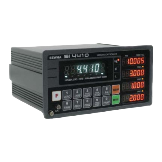
- Page 1 Digital Weighing Indicator Model : SI 4410 Operation Manual Version 1.21 (2007. 9)
- Page 2 CONTENTS 1. Before Installation 4 page --------------- 1-1. Caution / Warning Marks --------------- 4page 1-2. Other Marks --------------- 4page 1-3. Copy Rights --------------- 4page 1-4. Inquiries --------------- 4page --------------- 4page 2. Introduction 5 page --------------- 2-1. Introduction --------------- 5 page 2-2.
- Page 3 6. Interface 68 page --------------- 6-1. Serial Interface (RS-232C) --------------- 68 page 6-2. Current Loop Interface --------------- 71 page 6-3. Print Interface (Option 01 : Centronics Parallel Interface) --------------- 72 page 6-4. Analog Output Interface (Option 02 : 0~10V) --------------- 74 page 6-5.
-
Page 4: Before Installation
1. BEFORE INSTALLATION 1-1. Caution / Warning Marks Warning This mark warns the possibility to arrive death or serious injury in case of wrongly used. Caution This mark cautions the possibility to arrive serious human body injury or product lose in case of wrongly used. 1-2. - Page 5 With 2ports serial port interfaces and precise weighing control system, you can upgrade your weighing process. This “SI 4410” Weighing Controller has various kinds of “Weighing Mode”, like Limit, Packer, Loss- in Weighing(Minus Limit), so you can apply various kinds of weighing application.
- Page 6 3. SPECIFICATION 3-1. Analog Input & A/D Conversion Input Sensitivity 0.2㎶ / Digit Load Cell Excitation DC 10V ( - 5V ~ + 5V ) Max. Signal Input Voltage Max.32mV [Zero] ±16PPM/℃ Temperature Coefficient [Span] ±3.5PPM/℃ ±0.3㎶ P.P Input Noise Input Impedance Over 10㏁...
- Page 7 3-3. General Specification AC110/220V(±10%), 50/60Hz, about 30VA Power Supply Operating Temperature Range ℃ ~ 40 ℃ Operating Humidity Range Under 85% Rh (non-condensing) External Dimension 200mm(W)x105mm(H)x165mm(L) Net Weight(kg) About 2.3kg About 3.0kg Gross Weight(kg) ※ AC 110V, Power supply is an optional before ex-factory. 3-4.
- Page 8 3-5-1. Status Lamp (ANNUNCIATORS) : “▼” Lamp is “ON”. When the weight is Steady, “▼” Lamp is turn on. Steady When the current weight is Zero, “▼” Lamp is turn on. Zero (Displayed weight is Zero, “▼” Lamp is turn on.) Tare function is set, “▼”...
- Page 9 1. To START or STOP weighing process. First input, SI 4410 Controller Starts weighing process, and Second input, SI 4410 Controller stops weighing process. ※ This function will be activated under F21 -02, 04, 05, 06, 07 setting, only. You can set each weighing process as a certain P/N.
- Page 10 Whenever pressing “0”key, digit will be change 1, 2, 5, 10, and 50. - Decimal point position Whenever pressing “0”key, decimal point will be change. 1. Modify the set value during setting process. 2. Calibration mode - Move back to previous step. F-function Mode.
- Page 11 Print current P/N’s accumulated weighing count and weight. (Sub-Total Print) Set “Over N.G”(Error relay) range. (If you set larger value than FINAL value, the setting is not saved) Set “Under N.G”(Error relay) range. (If you set larger value than FINAL value, the setting is not saved) Display accumulated weighing count and weight Max.
- Page 12 3-6. Rear Panel Option Card(1) Option Card(2) AC Power Input Relay Output Terminal Load Cell Input External Input Serial Port(Standard) ① POWER AC IN - Power switch : Power on/off switch. - Fuse : AC250V / 0.5A , φ5.25 , 20mm. - AC IN : Available Input AC 110V / 220V.
- Page 13 4. INSTALLATION 4-1. External Dimension & Cutting Size (External Dimension) (unit : mm) 162.0 (Cutting Size) (unit : mm) - 13 -...
- Page 14 4-2. Assembly - 14 -...
- Page 15 4-3. Load Cell Installation 4-3-1. Load Cell Connector Specification White Green Blue Shield 4-3-2. Load Cell Installation 1). You can connect Max. 8pcs of same capacity Load cells at once. (350Ω) 2). You have to make horizontal balance on the ground. 3).
- Page 16 4). The load cell cable color can be different from each manufacturer, please refer following data sheet. 5). Load Cell Wire Color Chart (Sorted by Manufacturer) Manufacturers EXC+ EXC- SIG+ SIG- SHIELD Sewha CNM White Green Blue Black Bongshin, CAS ,TMI ,AND White Green Blue...
- Page 17 4-3-4. Formula to plan the precise weighing system This “SI 4410” weighing controller’s Max. input sensitivity is 0.2㎶ / Digit. And for precise weighing system, the following formula must be satisfied. Caution : “Input sensitivity” means Min. output voltage variation of weighing part to change 1digit.
- Page 18 5. SET-UP 5-1. Calibration Adjust weight balance between “Real weight” on the load cell(Weight Part) and “Displayed weight of Indicator”. When you replace LOAD CELL or Indicator, you have to do Calibration process once again 5-2. Test Weight Calibration Mode (Using Test weight) Prepare At least 10% of Max.
- Page 19 Decimal point position select with “0” key Press “Enter” and move the next step. Under this step, define the optimal position or Decimal point. Whenever pressing key, Decimal point will be changed, like XXX. – XX.X – X.XX - .XXX The Max.
- Page 20 Memorize “DEAD weight” of Weighing Machine Indicator will search “DEAD weight” during with “Enter”. 5sec, automatically. Under this step, measure the “DEAD Weight of Weighing Scale”. This “DEAD Weight” is very important to make “ZERO” value of weighing scale, so please make sure that the weighing scale is empty and free from other external variations.
- Page 21 Input prepared Test weight value and press key, then message will be displayed. Then load Test weight on weighing scale and press key. Then, indicator will make adjustment for “Standard weight value” and calculate “Span value”. ※ “At least 10%” means to guarantee precise weighing process you have to make standard with at least 10% of weight of Max.
- Page 22 5-3. Simulation Calibration Mode (Calibrate without Test weight) Through this “Simulation Calibration Mode” you can make simple calibration without Test weight. This calibration mode uses “Load cells’ max. capacity” and “Max. Output Rate(mV)”, the weight adjustment degree might be less than “Test weight Calibration”. The guaranteed resolution of this “Simulation Calibration”...
- Page 23 Please input this max. capacity of load cell value with No. keys. After finishing input, press key and save and move to next step. Caution ※ If the plural No. of load cells are installed, please make sum the all load cells capacity and input. Ex) There are 4pcs of load cells are installed, and each load cell’s Max.
- Page 24 and move to next step. Caution ※ (Max. capacity value / division value) can not be over 20,000.(as Indicator resolution is 1/200,00). If the value is over 20,000, Error message “ Err 01 “ will be displayed and move back “CAPA” mode again.
- Page 25 Under this step, input Max. Output rate(mV) of load cell. The Output rate is stated on “Test report” or “Label” and please input this value with No. keys. Normally, the Output rate will be 4digits under Zero, then input 4digits and input “0” additionally and make full 6digits.
- Page 26 5-4. Set-up Set-up means set the F-function and make SI 4410 weighing controller will perform more accuracy. (Considering external / internal environmental condition) 5-4-1. Enter the Set-up Mode 1). Method : Press key for 4sec. Then you can enter “F-Test” mode. Under this mode, press No.1 key and enter the “F-function”...
- Page 27 5-5. F-Function List General Function Setting Weighing Data Save Method selection 0, 1, 2 0, 1 Weight-Back up selection MOTION BAND Range setting 0 ~ 9 ZERO TRACKING Compensation 0 ~ 9 Range setting Auto Zero Range setting 00 ~ 99 Digital Filter setting 01 ~ 99 “Zero/Tare”...
- Page 28 Communication Mode setting Parity Bit selection Mode 0, 1, 2 Serial Communication Speed selection 0 ~ 9 DATA Transference Method selection 0, 1 Print Port selection 0, 1 (Under F32-01 setting, only) “Check-Sum” detection selection 0, 1 (Under F32-01setting, only) Serial Port application selection 0, 1 (Under F32-00 setting, only)
- Page 29 TIME check/change XX. XX. XX Program & Hard ware Version Check X.XX X.XX. X Production Date Check. XX. XX. XX Option - Optional Serial Port(Port2) setting 0, 1, 2 Parity Bit selection Mode Serial Communication Speed selection 0 ~ 9 DATA Transference Method selection 0, 1 “Print Command-data”...
- Page 30 5-6. F-Function Detailed information ■ General Function Setting (● Factory default set value) Weighing Data Save Method Selection (Apply on Accumulated weighing count/weight) ● Manual Save Mode (Save when “Print” key input) Automatic Save Mode(Save when weighing is Finished) Combined Save Mode (Save when “Print”...
- Page 31 ※ Caution Under this setting, “Saved data” and “Printed data” is same. So, this setting is recommended for Automatic weighing process. 5. F01-02, F38-00 setting (Combined Save mode(Auto + manual save mode) + manual print mode When “Finish relay” output, finished data will be saved automatically, but same data will not be printed. And also, if there is additional key input, weighing data will be saved once again and printed out.
- Page 32 ※ Weight Back up Mode Under this mode, SI 4410 memory “Zero” value of weighing part. So, when the power is recovered SI4410 can display material weight. If you remove and turn on the power, please press “Zero” key and re-memorize Zero value.
- Page 33 Zero Tracking Compensation Range setting Due to external causes(Temperature, wind, and dust), there are small weight difference, indicator will ignore the weight difference and display Zero. For this compensation function, indicator will estimate the weight ∫ difference is over the set range during fixed time period. If there is large weight difference over set range within fixed time period, the “Zero”...
- Page 34 Digital Filter setting If “B” set value is fixed, A : Frequency Filter setting value (0~3) “A” set value is large, the (0 : about 200Hz/sec, 3 : about 500Hz/sec) indicator will response B : Buffer Filter setting value (1~9) more sensitive.
- Page 35 External Input Selection Set Value Input 1 Input 2 Input 3 Input 4 STOP TARE TARE RESET TARE/ RUN/STOP ZERO PRINT TARE RESET SUB-TOTAL ● STOP PRINT PRINT NET WEIGHT/ ZERO TARE TARE RESET GROSS WEIGHT STOP ZERO PRINT ※ The Input signal pulse must be more than 1msec. ※...
- Page 36 Display Up-date rate selection About 10ms About 30ms ● About 50ms ∫ ∫ About 170ms About 190ms (FINAL, PRE1, PRE2, Free Fall) Set value apply selection ● Apply only certain P/N Apply same set value to all P/N ※ Under F14-01 setting, after set this value and you have to input new set values for each set point (FINAL, PRE1, PRE2, FREE FALL).
- Page 37 “NEAR ZERO” relay output mode selection Display weight is Zero(Including “TARE” Zero) Near Zero relay ● output Only Gross Zero(Net weight + TARE) Near Zero relay output ※ Under F17-01 setting, even if the TARE is set and display weight is Zero, there is no NEAR Zero relay output.
- Page 38 SI 4410 program. weighing process apply operator’s set “Free fall” value. weighing process controlled by SI 4410 program. And gathering 3 weight variation data. - from 5 weighing process apply averaged value of 3times weighing process’s weight variations.
- Page 39 Weighing Mode selection ● Limit Mode (Low / High relay) Packer Mode - (Finish / Error relay) - RUN key input weighing start Loss-in Weight 1. ( Low / High relay) - TARE key input weighing start Loss-in Weight 2. (PRE1 : Feeding, PRE2, Free Fall : Discharge), (Low / High relay) - RUN key input weighing start Loss-in Weight 3.
- Page 40 Weighing Mode 1. Limit Mode (F21 -01 setting) - No Finish Relay output. ◆ Weight ※ This Flow chart was made based on FINAL “LOW/HIGH” set value is “0” PRE 2 PRE 1 Near Zero TARE input Output1 PRE 1 PRE 2 Output2 FINAL...
- Page 41 Weighing Mode 2. Packer Mode (F21 -02 setting) - Finish / Error Relay output ◆ FINAL Set Weight FINAL HIGH PRE 2 Pass FALL PRE 1 Near Zero TARE input START PRE 1 Output1 PRE 2 Output2 FINAL Output3 FINISH Output4 ERROR Output5...
- Page 42 Weighing Mode 3. Loss -in Weight Mode 1. (F21-03 setting) - No Finish/Error Relay output ◆ ※ This Flow chart was made based on Weight “LOW/HIGH” set value is “0”. Near Zero PRE 1 FALL PRE2 FINAL FINAL Set TARE input TARE Reset PRE 1 Output1...
- Page 43 Weighing Mode 4. Loss -in Weight Mode 2 - No Finish/Error Relay output ◆ PRE 1 Weight ※ This Flow chart was made based on “LOW/HIGH” set value is “0 Near Zero FALL PRE 2 FINAL FINAL Set TARE input TARE reset START PRE 1...
- Page 44 Weighing Mode 5.. Loss -in Weight Mode 2) - Finish / Error Relay output ◆ Weight PRE 1 Near Zero HIGH FALL PRE 2 PASS FINAL FINAL Set TARE input TARE reset START PRE 1 Output1 PRE 2 Output2 FINAL Output3 FINISH Output4...
- Page 45 Weighing Mode 6. Loss -in Weight 3. - Finish / Error Relay output ◆ PRE 2 Weight PRE 1 Near Zero FALL PASS FINAL HIGH FINAL Set TARE Input TARE Reset START Output 1 PRE 1 Output 2 PRE 2 Output 3 FINAL Output 4...
- Page 46 Weighing Mode 7. Loss -in Weight 4. (2step Feeding, 1step discharge, F21-07 setting) ◆ - No Finish/Error Relay output PRE 2 Weight ※ This Flow chart was made based on PRE 1 “LOW/HIGH” set value is “0 Near Zero FALL FINAL FINAL Set TARE input...
- Page 47 “FINISH Relay” delay time(t1) setting (Under F01, 05, 06 setting) After current weight is reached to FINAL, you can set some delay time of “FINISH relay ON time. Steady point ∫ FINISH Relay Com-Out4 “00” setting : At Steady point, FINISH relay output “20”...
- Page 48 Manual Discharge selection (Under F21-04, 05, 06, 07 setting) ● Manual Discharge Not Use. Manual Discharge Use. (If you press “F” + “RUN/STOP” key, discharge gate will be open during 5sec.) ※ Under Loss-In weight Mode(F21-02, 04~07), and Packer Mode setting. If you press Manual Discharge function, all feeding gate will be open during 5sec, and LED display will blink and inform to operators about “Manual Discharging operation”.
- Page 49 ■ Communication Mode setting (Serial Port 1. - Standard installed port) Parity Bit selection Mode ● No Parity Odd Parity Even Parity Serial Communication Speed selection 2,400bps 4,800bps ● 9,600bps 14,400bps 19,200bps 28,800bps 38,400bps 57,600bps 76,800bps 115,200bps ※ When you set the “Serial Communication Speed”, you have to estimate your P.C’s spec. If you use normal P.C, you had better to set with 0, 1, or 2 set value.
- Page 50 Print port selection (Under F32-01 setting, only) ● Same port as using for Command Mode. The other port. ※ Through this function, you can selection print port, which will be used for print, when indicator takes a “Print Command” from P.C. If you choose F33-00, the print data will be transfer to P.C with print format.
- Page 51 Print Mode selection (Under F32-00, F35-01 setting, only) ● Manual Print : Whenever “Print” key input. Auto Print : When Finish relay output, automatically print. Transferring DATA Byte selection ● 7 Byte data Transfer 8 Byte data Transfer ※ Under F37-02 setting(CAS Format), Transferring DATA byte is fixed as 7byte. Under F37-00, 01 setting (Format 1, Format 2), you can selection 7 or 8byte.
- Page 52 SUB/GRAND Total Data Delete selection Manual Delete Mode ● SUN Total Delete : “Clear” key + “P/N” key GRAND Total Delete : “Clear” key + “S/N” key Automatic Delete Mode After SUB/GRAND Total Print, Automatically Deleted. Paper Withdraw Rate setting (After SUB/GRAND Total Print) ∫...
- Page 53 Parallel Print Port selection ● Parallel Port is not installed. Share Standard Serial Port. Share Optional Serial Port. ※ If you install “Print interface option(Centronics Parallel), you have to choose, which port you will use for print data transference to “Print Interface”. If you installed “Print interface”, but you didn’t choose the port, you can not print out through Parallel print.
- Page 54 SPAN Calibration Value Check Span Calibration Value Check Under F-function mode, enter “ ”, “ ” key and press “ ”. X.X.X.X.X.X. After checking the value and press “ ” to exit ※ If you have difficulty to process Calibration again, the best way to matching the net weight and display weight is doing Calibration process once again.
- Page 55 ■ Communication Mode setting (Serial Port 2. - Optional Serial port) This setting will be activated only when “Optional Serial Port” is installed. Parity Bit selection Mode ● No Parity Odd Parity Even Parity Serial Communication Speed selection 2,400bps 4,800bps ●...
- Page 56 Print port selection (Under F62-01 setting, only) ● Same port as using for Command Mode. The other port. ※ Through this function, you can selection print port, where indicator takes a “Print Command” from P.C. If you choose F63-00, the print data will be transfer to P.C with print format. If you choose the other port, the print data will be transfer through the other port.
- Page 57 Print Mode selection (Under F62-00, F65-01 setting, only) ● Manual Print : Whenever “Print” key input. Auto Print : When Finish relay output, automatically print. - 57 -...
- Page 58 ■ Serial Port Setting Examples ※ Other set values, except example, are not influence the performance. 1. Only one Serial port is installed A. Command mode Setting Standard Serial Port Setting F32-01 : Command Mode F33-00(Nominate Printing port for “PRINT COMMAND”) –...
- Page 59 D. Serial Print installed Standard Serial Port Setting F32-00 : Simplex Mode setting F35-01 : Print Mode setting F38-00/01 : 00 setting : Manual Print Mode( key input, 1time Print out) 01 setting : Auto Print Mode (When “Finish Relay” output, 1time auto Print out) ※...
- Page 60 CASE 2. Standard Serial Port Setting – Data Transference Mode(P.C Monitoring) F32-00 : Simplex Mode setting F35-00 : Data Transference Mode F36-00/01/02 : 00(Steam Mode) 01(When “Finish Relay” Output, 1time transfer) 02(When key input, 1time transfer) F37-00/01/02 : Transferred Data format setting F40-00/01 : Transferred Data Byte Setting (Under F37-02 setting, F40-00 fix) Optional Serial Port Setting –...
- Page 61 CASE 2. Standard Serial Port Setting – External Display Mode F32-00 : Simplex Mode Setting F35-00 : Data Transference Mode F36-00 : Stream Mode Fix F37-00/01/02 : Transferred Data format setting. F40-00 : Under “External Display” mode, F40-00 Fix Optional Serial Port Setting – Command Mode F32-01 : Command Mode F33-00(Nominate Printing port for “PRINT COMMAND”) –...
- Page 62 CASE 2. Standard Serial Port Setting – Serial Print Mode F32-00 : Simplex Mode setting F35-01 : Print Mode setting F38-00/01 : 00 setting : Manual Print Mode( key input, 1time Print out) 01 setting : Auto Print Mode (When “Finish Relay” output, 1time auto Print out) Optional Serial Port Setting –...
- Page 63 CASE 2. Standard Serial Port Setting – External Display Mode F32-00 : Simplex Mode Setting F35-00 : Data Transference Mode F36-00 : Stream Mode Fix F37-00/01/02 : Transferred Data format setting. F40-00 : Under “External Display” mode, F40-00 Fix Optional Serial Port Setting – Data Transference Mode F62-00 : Simplex Mode setting F65-00 : Data Transference Mode F66-00/01/02 : 00(Steam Mode)
- Page 64 CASE 2. Standard Serial Port Setting – Serial Print Mode F32-00 : Simplex Mode setting F35-01 : Print Mode setting F38-00/01 : 00 setting : Manual Print Mode( key input, 1time Print out) 01 setting : Auto Print Mode (When “Finish Relay” output, 1time auto Print out) Optional Serial Port Setting –...
- Page 65 CASE 2. Standard Serial Port Setting – Serial Print Mode F32-00 : Simplex Mode setting F35-01 : Print Mode setting F38-00/01 : 00 setting : Manual Print Mode( key input, 1time Print out) 01 setting : Auto Print Mode (When “Finish Relay” output, 1time auto Print out) Optional Serial Port Setting –...
- Page 66 H. Standard Serial Port & Optional Serial Port – Data Transference Mode(P.C Monitoring) Standard Serial Port setting – Data Transference Mode F32-00 : Simplex Mode setting F35-00 : Data Transference Mode F36-00/01/02 : 00(Steam Mode) 01(When “Finish Relay” Output, 1time transfer) 02(When key input, 1time transfer) F37-00/01/02 : Transferred Data format setting...
- Page 67 J. Standard Serial Port & Optional Serial Port – Serial Print Mode Standard Serial Port Setting – Serial Print Mode F32-00 : Simplex Mode setting F35-01 : Print Mode setting F38-00/01 : 00 setting : Manual Print Mode( key input, 1time Print out) 01 setting : Auto Print Mode (When “Finish Relay”...
- Page 68 6. INTERFACE 6-1. Serial Interface (RS-232C) RS-232C Serial Interface is sensitive/weak for electric Noise. So, please isolate with AC power cable and use shield cable to reduce the electric noise effect. 6-1-1. Signal Format ①. Type : EIA-RS-232C ②. Communication Method : Half-Duplex, Full Duplex, Asynchronous ③.
- Page 69 ②. Header 2. : NT : Net-Weight GS : Net-Weight, under TARE. ③. Data Bit(Number) 2B(H) : “+” Plus 2D(H) : “-“ Minus 2D(H) : “ “ Space 2E(H) : “.” Decimal Point ④. Unit : kg, g, t 6-1-3. Data Format(2) : ID Number + Data Transference (Refer “F-function 34,35) ID Number Header 1 Header 2...
- Page 70 6-1-5. Communication with PC(Personal Computer) or Other devices 2 : RxD TxD : 3 3 : TxD RxD : Personal Computer 5 : SG SG : 5 SI 4410 (9pins Standard) 6-1-6. RS-232C Circuit 2 : RxD 3 : TxD 5 : SG - 70 -...
- Page 71 As same as “RS-232C” Interface 6-2-3. Communication with Other Devices (Remote Display / External Display) 3 : RxD TxD : 8 4 : RxD TxD : 9 SI 4410 Remote Display (External Display) 6-2-4. Current Loop Circuit - 71 -...
- Page 72 6-3. Print Interface (Option 01 : Centronics Parallel Interface) This Print Interface Option is based on “Centronics Parallel Interface”, so this print interface can be connected other printers using this communication method. But, the print format is programmed based on our “SE7300”, and “SE7320” Industrial Printers, so you had better to use these printer for convenience.
- Page 73 6-3-4. Typical Interface Circuit Signal Name Circuit Sample BUSY, ACK Input (From Printer) Data0 ~ Data7 (To Printer) Output STROBE (To Printer) 6-3-5. Print Format (English) Single Print Format Continuous Print format DATE : 2006-10-15 Date : 2006-10-15 TIME : 10:20:30 Time : 10:20:30 ID_N PART SERIAL WEIGHT ID_N PART SERIAL WEIGHT...
- Page 74 6-4. Analog Output Interface (Option 02 : 0~10V Output) This Option card converts weight value to Analog Voltage output(0~10V) and transfers to external devices(Recorder, P.L.C), controlled by voltage output. 6-4-1. Specification ①. Output Voltage : 0~10V DC output ②. Accuracy : More than 1/1,000 6-4-2.
- Page 75 6-5. Analog Output Interface (Option 03 : 4~20mA Output) This Option card converts weight value to Analog Electric Current output(4~20mA) and transfers to external devices(Recorder, P.L.C), controlled by electric current output. 6-5-1. Specification ①. Output Current : 4~20mA (Output Range : 2~22mA) ②.
- Page 76 6-6. Serial Interface (option 04 : RS-232C/422/485) RS-422/485 serial interface is more stable for electric noise effect compare with other communication method, using electric current difference. But, install isolated place from Power cable or other electric cables and wires, and please use shielded cable for better performance.
- Page 77 6-7. BCD Input Interface( Option 05) – Input for Part No. selection. This “BCD interface” option card can be applied on PLC (Programmable Logic Controller), or Score Board applications. Each Input circuit is isolated with “Photo-Coupler”, from external devices electrically. Wire Connection Diagram - 77 -...
- Page 78 ※ Each “READ” Command’s interval must be guaranteed at least 100ms. If you command another one within 100ms, the indicator will not response. (Under “Check-Sum”, the interval will be 150ms). P.C ->> SI 4410 Command SI 4410 Response Current Weight Transfer STX ID NO.
- Page 79 Finished Weight Data Transfer STX ID NO. RFIN ETX Finished Weight -STX ID NO. RFIN Finished Weight(7/8byte) ETX Current Time Data Transfer STX ID NO. RTIM ETX Current Time Data -STX ID NO. RTIM Current Time(6byte) ETX Current Date Data Transfer STX ID NO.
- Page 80 6-8-2. Write Command ※ Each “WRITE” Command’s interval must be guaranteed at least 150ms. If you command another one within 150ms, the indicator will not response. (Under “Check-Sum”, the interval will be 200ms). P.C ->> SI 4200 Command SI 4200 Response STX ID NO.
- Page 81 6-8-3. Command Mode Example - “Check-sum” not use (F34-00 setting). READ COMMAND Format STX(1) ID NO.(2) COMMAND(4) ETX(1) Example) Current Weight Command(RCWT), ID No. : 01, Current Weight : 1,000kg. P.C Command Format (STX ID NO. RCWT ETX) 30h 31h 52h 43h 57h 54h Header ID No.
- Page 82 Indicator Response Format (Normal Operation) 30h 31h Header ID No. Indicator Response Format (Error) 30h 31h Header ID No. 6-8-4. Command Mode Example - “Check-Sum” function using(F-34-01 setting) READ COMMAND Format STX(1) ID NO.(2) COMMAND(4) BCC(2) ETX(1) ※ Under “Check-Sum” using mode(F-34-01 setting), summing all the data from “02” to “03” and convert to ASCII code and transfer to P.C If the calculated value is “02”, the transferred data will be “30h 32h”.
- Page 83 WRITE COMMAND Format STX(1) ID NO.(2) COMMAND(4) REQUEST DATA BCC(2) ETX(1) ※ Under “Check-Sum” using mode(F-34-01 setting), summing all the data from “02” to “03” and convert to ASCII code and transfer to P.C. If the calculated value is “02”, the transferred data will be “30h 32h”.
- Page 84 7. Error & Treatment 7-1. Load Cell Installation Error Cause Treatment Remark 1).Input Resistance of 1). Load cell broken 1). Measure input/output “EX+” and “EX-“ is 2). Load cell isolation resistance of Load cell. about 350Ω~450Ω. resistance error 3). Weighing part Weight Value is 2).
- Page 85 7-2. Calibration Process Error Cause Treatment When Max.capacity/digit Re-input the Max. Capacity, less than 20.00 Err 01 value is over 20.00 (Max. Capacity / Digit) Standard weight value is over Re-input Standard weight value with Number keys, Err 04 than Max. Capacity under Max.
- Page 86 7-3. Digital Weighing Indicator Error No. Display Cause Treatment 1. Under “TEST” mode 1, check analogue value. If you can not get any analogue value or there is no change although adding load, please check “CELL-Er” 1. Load cell Error load cell, load cell cable, connection 2.
- Page 87 7-4. Indicator Test mode Through this “Test Mode”, you can check basic conditions of Indicator. This Test consists with total 7 tests. 7-4-1. Enter “Test Mode” Press key for 4sec, then display will show “F-Test”. Under this display, press No.2 key and enter the “Test Mode”. Under “Test Mode”, please choose each test and check the basic conditions of Indicator.
- Page 88 Under “TEST” display, press No.4 key and Enter “TEST4” mode. Test 4. External Input If you press External input S/W, the External S/W No. will be displayed. Test If the S/W No. is not displayed, please check connecting condition. Under “TEST” display, press No.5 key and Enter “TEST5” mode. After connecting No.2 and 3 pin of 9pin connector, you can test Test 5.
- Page 89 - Any kinds of “Warrantee Certification” without authorized Stamp is out of validity Manufacturer Digital Weighing Indicator Product SEWHACNM Co.,Ltd. Model SI 4410 310, Kolon Techno Valley, 60-4, Kasan-dong, Serial No. Keumcheon-gu, Seoul, Korea Website : http://www.sewhacnm.co.kr AUTHORIZED Made in KOREA...
Need help?
Do you have a question about the SI 4410 and is the answer not in the manual?
Questions and answers