Table of Contents
Advertisement
Quick Links
Advertisement
Table of Contents

Related Manuals for Sewha SI 550


Summary of Contents for Sewha SI 550
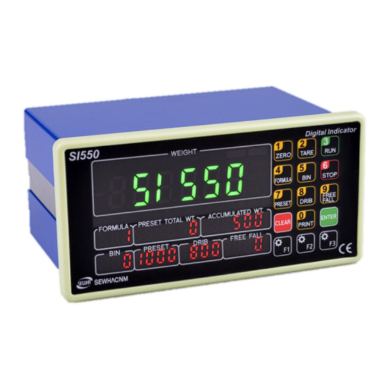
- Page 1 Digital Weighing Indicator SI 550 USER Manual Ver. 1.0 2017.09.05...
-
Page 2: Table Of Contents
SI 510 WEIGHING INDICATOR INDEX 1. BEFORE INSTALLATION ..................- 4 - 2. Introduction ......................- 5 - 2-1. Introduction ......................... - 5 - 2-2. Cautions........................- 5 - 2-3. Features ........................- 5 - 3. Specification......................- 6 - 3-1. - Page 3 SI 510 WEIGHING INDICATOR 6-5. Analogue I-Output Interface (4~20mA) .............. - 52 6-6. Analog V-Output Interface (0~10V) ..............- 53 6-7. Analog output selection ..................- 54 6-8. Print Interface ......................- 54 6-9. BCD IN card (Changing Product number) ............-56 6-10 BCD OUT Card (Weight data out) ...............
-
Page 4: Before Installation
Copy Rights 1. All Right and Authority for this manual is belonged to SEWHA CNM CO., LTD. 2. Any kinds of copy or distribution without permission of SEWHA CNM CO.,LTD will be prohibited. -
Page 5: Introduction
SI 510 WEIGHING INDICATOR 2. Introduction 2-1. Introduction Thank you for your choice of this "SI550" Industrial Digital Weighing Indicator. This "SI550" model is high-performance weighing indicator. We support Serial communication, ETHENET, BCN IN/OUT, Analog out, SD MEMORY CARD. Please review and learn this instruction Manual and enjoy your process efficiency with "SI550"... -
Page 6: Specification
SI 510 WEIGHING INDICATOR 3. Specification 3-1. specification Content Specification Display Resolution 1/20,000 Internal Resolution 1/2,000,000 (±1,000,000) Input sensitivity Min 0.1µV/V Max signal input voltage Max 3.0mV/V Load cell excitation DC +5V Analog Part A/D conversion method Sigma-Delta Decimal point 0, 0.0, 0.00, 0.000 Offset 10PPM/℃... -
Page 7: State Led
SI 510 WEIGHING INDICATOR 3-2. Option Option 1 Serial Port (RS-422) Option 2 Serial Port (RS-485) Option 3 Serial Port (RS-232) Option 4 ETHERNET CARD Option 5 Analog Output(4~20mA) Option 6 Analog Output(0~10V) Option 7 BCD OUT Option 8 BIN IN Option 9 SD Memory Card 3-3. - Page 8 SI 510 WEIGHING INDICATOR 3-3-1. Key operation - Press 4 times within 3secs, to enter to Function setting mode. - Press 4 times within 3secs, to enter to “Hidden function” mode. - Make the Weight Value to Zero - Number 1 - Set the Tare Function - Number 2 - Use for Run weighing...
- Page 9 SI 510 WEIGHING INDICATOR 3-3-2. Hot key Use for tare value setting Use for over tare weight setting Use for under tare weight setting Use for compulsory finish Over weight setting Under weight setting Subtotal weight Print Delete subtotal P/N's accumulated weighing count and weight Set the procedure of BIN Delete accumulated weight for each BIN Print accumulated weight and all count of formula...
-
Page 10: Behind Of The Si550
SI 510 WEIGHING INDICATOR 3-4. Behind of the SI550 (1)Power (5) Relay output (4)Loadcell Input (2) External (3)Serial I/F (1) AC Power input terminal (2) External input terminal: User selectable 6EA (3) Serial Interface terminal Terminal RS – 232 (4) Loadcell Input terminal Terminal EXC+ EXC-... -
Page 11: Installation
SI 510 WEIGHING INDICATOR 4. Installation 4-1. External Dimension & Cutting Size 4-2. Installation Components SI 550 Main Body User Manual - 11 -... -
Page 12: Load Cell Installation
SI 510 WEIGHING INDICATOR 4-3. Load Cell Installation Load Cell Wire Connection (In case of SEWHACNM’s Load cell) It depends on the manufacturer of load cell, please check the specification. - Under Set-up the Load cell, if EXC+ and EXC- have a short circuit, It may cause damage in the indicator.(specially analogue board) - If you connect other wires to Load cell terminal wrongly, it may cause damage in the analogue board. -
Page 13: Set-Up
SI 510 WEIGHING INDICATOR 5. SET-UP 5-1. Test Weight Calibration Mode (Using Test Weight) 5-1-1. Calibration Mode Calibration is the process of adjusting weight balance between "Real Weight" on the Load Cell and "Displayed weight of Indicator". When you replace Load Cell or Indicator, you have to do Calibration process once again. - Page 14 SI 510 WEIGHING INDICATOR 5-1-2. Test Weight Calibration Mode (Using Test Weight) STEP 1 1) Remove "CAL-BOLT" on the real panel. 2) Press "CAL-LOCK S/W" inside. STEP 2 – Setting "Capacity of weighing scale" 1) When "CALIBR" display. 2) Press "F1"...
- Page 15 SI 510 WEIGHING INDICATOR STEP 3 – Decimal point and division setting 1) After "DIVI" is displayed, locate the decimal point with "F1"key. 2) Set the division with "F2" key. Press enter key to save. Max decimal point will be 0.0001, and digit can be selected among 1,2,5,10,20,50. Digit and decimal point must be fulfilled under the below condition.
- Page 16 SI 510 WEIGHING INDICATOR STEP 5 – Calculation Span Value 1) If the count is over, "SPAN" will be displayed. 2) Input the weight of your "Test Weight" and press "ENTER" key. 3) If "UP" is displayed, Please load "Test Weight"...
-
Page 17: Simulation Calibration Mode (Calibrate Without Test Weight)
SI 510 WEIGHING INDICATOR 5-2. Simulation Calibration Mode (Calibrate without Test Weight) With this "Simulation Calibration Mode" you can make simple calibration without any "TEST weight". This calibration mode uses "Load cells max capacity" and "Max Output Rate (mV)", so the weight adjustment degree might be less than "Test Weight Calibration". - Page 18 SI 510 WEIGHING INDICATOR STEP 3 – Setting "Capacity of Load Cell" 1) "CAPA" become displayed. 2) Check the Max Capacity of Load Cell and Input the Max Capacity to Load cell. (Refer to the load cell label or Test Report.) And Press "ENTER"...
- Page 19 SI 510 WEIGHING INDICATOR STEP 5 – Measuring the “DEAD Weight” of Weighing Scale. 1) When "DEAD" displays, Press Enter key. 2) Then indicator will calculate dead weight of scale part automatically. ( While this process, there should be nothing on the scale part. ) ...
- Page 20 SI 510 WEIGHING INDICATOR 4) Calculated span value will be displayed. Then press enter key to finish the calibration step. In case of multiple pieces of load cells are connected, the rated output will be same as single load cell’s. (Because plural load cells are connected with parallel connection, the sum of rated output voltage is same as single load cell’s rated output) ※Due to some variation between “State output rate”...
-
Page 21: F-Function Setting
SI 510 WEIGHING INDICATOR 5-3. F-FUNCTION Setting STEP 1 – Starting F-FUNCTION Mode 1) Press "F1" key 4 times. 2) When "SET-UP" is displayed, Press number 1 key. STEP 2 – Explanation of details. Set Value Function No. 1) "F1"... - Page 22 SI 510 WEIGHING INDICATOR 5-3-1. F-Function List List Subject Contents Equipment No. setting – ID 01~99 No.setting Weight–Back up Mode 00 : Normal mode 01 : Weight Back up Mode(Zero) 02 : Weight Back up Mode(Zero & Tare) Weighing Data Save Method 00 : Manual : Whenever “Print”...
- Page 23 SI 510 WEIGHING INDICATOR Sub-total date delete after printing 00 : No delete 01 : Delete Grand-total date delete after 00 : No delete printing 01 : Delete Steady Range 01 ~ 99 (Unit : 0.25 : 0.25: 0.25 gradation ) Steady condition check time 01 ~ 99 (Unit : 0.1 : 0.1: 0.1 sec) Digital Filter Setting...
- Page 24 SI 510 WEIGHING INDICATOR External Digital Input 1 00: Disuse 01: Run External Digital Input 2 02: Stop External Digital Input 3 03: Complete BIN with enforce External Digital Input 4 04: Reset BATCH External Digital Input 5 05: Make Zero External Digital Input 6 Communication Setting Port 1 Parity / Stop bit...
- Page 25 SI 510 WEIGHING INDICATOR Set displayed data for Port 1 00 : Current Weight (Same as main display) Simplex 01 : Accumulated Weight (accumulated value by Batch process) Port 2 Parity / Stop bit 00: Data bit8, Stop bit1, Parity bit Non 01: Data bit8, Stop bit1, Parity bit Odd 02: Data bit8, Stop bit1, Parity bit Even 03: Data bit7, Stop bit1, Parity bit Odd...
- Page 26 SI 510 WEIGHING INDICATOR Date transference under Ethernet 00 : Simplex / Stream Mode 01 : Duplex / Command Mode 02 : Modbus (TCP/IP) Data Format under Ethernet 00 : Format 1 (18byte) Stream Mode Ethernet 01 : Format 2 (22byte) 02 : Format 3 (17byte) 03 : Format 4 (22byte) Date transference under Ethernet...
- Page 27 SI 510 WEIGHING INDICATOR BIN OUT Setting (BIN No. Output) 00 : Output Unit digit and Tenth digit separately 01 : One to One Output (OUT1=BIN 1…OUT8=BIN8) SD_Setting 00 : Disuse 01 : Use SD_Print Auto Save 00 : Disuse 01 : Use Subject Control Setting...
- Page 28 SI 510 WEIGHING INDICATOR Tare Setting Zero Output Use 00 : When weight is zero with tare input, Zero relay output is not activated 01 : When weight is zero with tare input, Zero relay output is activated Run time Auto Tare Setting 00 : Disuse 01 : Use Tare Release Time...
- Page 29 SI 510 WEIGHING INDICATOR <Weighing Mode> - 29 -...
- Page 30 SI 510 WEIGHING INDICATOR 5-3-2. Hidden Function Setting Mode This setting become enter the hidden Function.. How to enter Hidden Function Setting Mode : Press "F2" key 4 times and input your password. (1111) * Key function: F1 – Move hidden function number / Enter – Save Serial Number Check HF01 Check your device's serial number.
- Page 31 SI 510 WEIGHING INDICATOR Ip Address Check / Modification HF17 Check the Ip Address. Ip Address Check / Modification HF18 Check the weight of test weight which is used for your last calibration. Ip Address Check / Modification HF19 Check the analog value of ZERO. GateWay Check / Modification HF20 Check the GateWay and can modify.
-
Page 32: Test Mode
SI 510 WEIGHING INDICATOR 5-4. Test Mode Test mode for Indicator. 5-4-1. Enter to Test Mode Test mode is on, if press when Press 4times “SETUP” is displayed. Shortcut Test Mode Press 4 times Analog value Press 4 times ... -
Page 33: Test Mode Detail Information
SI 510 WEIGHING INDICATOR 5-5. Test Mode Detail information Before starting the TEST mode, please remove other connected devices. STEP 1 : Press 4times -> “SETUP” mode is on. -> 5-5-1. Analog Value (Press 4times –> –> You can check analog value. Small variation of analog value is normal. - Page 34 SI 510 WEIGHING INDICATOR 5-5-3. Key test (Press 4times –> Press –> Each key on the screen show 5-5-4. Display test ( Press 4times (1) FND test mode. (2) Turn on FND and LED by 1 Segment gradually. 5-5-5.
- Page 35 SI 510 WEIGHING INDICATOR 5-5-7. Analog Output 4~20mA, 0~10V ( Press 4times Analog output simulation : 0(4mV,0V)~20(20mV,10V) If the range is 4~20mA, A will be displayed. If the range is 0~10V, V will be displayed. Use left and right key to check the output value with unit 0.1. If entered value is over maximum value, actual output will be 100% of that range.
-
Page 36: Interface
SI 510 WEIGHING INDICATOR 6. INTERFACE 6-1. Serial Interface 6-1-1. Main Serial Interface (1) RS - 232 6-1-2. Optional Serial Interface (1) RS – 232 Indicator Option Card - 36 -... - Page 37 SI 510 WEIGHING INDICATOR (2) RS – 422 Indicator Option Card 32 pcs of Indicator are connectable (3) RS – 485 - Serial communication interface is sensitive to electric noise. - Install isolated place from Power cable or other electric cables and wires, and please use shielded cable for better performance - 37 -...
- Page 38 SI 510 WEIGHING INDICATOR 6-1-3. Data Format (1) Data Format1: ID Number is not transferred. (Refer F-function 203-00) – 18 byte Header1 Header2 OL : OVER LOAD NT : NET-WEIGHT(Tare is not set) ST : STEADY GS : when setting TARE US : UNSTEADY (2) Data Format 2 : ID Number+Data Transference (Refer F-function 203-01) –...
- Page 39 SI 510 WEIGHING INDICATOR (4) Data Format 4 : ID Number (Refer F-function 302-03) – 22 byte ID Number : F-function 101 Header1 Header2 OL : OVER LOAD NT : NET-WEIGHT(Tare is not set) ST : STEADY GS : when setting TARE US : UNSTEADY Lamp Display information Bit 0...
- Page 40 SI 510 WEIGHING INDICATOR 6-1-4. Command Mode Under “Command Mode”, Indicator will recognize the receipt of Order based on 02h(STX) and 03h(ETX) signal, and transfers 06h(ACK), 15h(NAK). 6-1-5. Read Command (Standard Serial Port and Optional Port is same / SI4500 compatibility) Current Weight Data ASCII : STX ID(2Byte) RCWT ETX...
- Page 41 SI 510 WEIGHING INDICATOR ASCII : STX ID(2Byte) RDRI ETX Total Length Receive: STX + ID(2Byte) + RDRI + ETX [8Byte] 8 byte SI 4500 Transmit: STX + ID(2Byte) + RDRI + PRE 1 value(5byte) + ETX 13 byte response [13Byte] Current Weighing BIN’s Free fall ASCII : STX ID(2Byte) RFRE ETX...
- Page 42 SI 510 WEIGHING INDICATOR 6-1-6. Write Command (SI4500 compatibility) Transmit (Normal): STX + ID(2Byte) + ACK + ETX [5Byte] Transmit (Error): STX + ID(2Byte) + NAK + ETX [5Byte] Make Zero ASCII : STX ID(2Byte) WZER ETX 8 byte SI 4500 Normal : STX + ID(2BYTE) + ACK Error : STX + ID(2BYTE) + NAK Normal : 5 byte...
- Page 43 SI 510 WEIGHING INDICATOR ASCII : STX ID(2Byte) WRUN ETX 8 byte SI 4500 Normal : STX + ID(2BYTE) + ACK Error : STX + ID(2BYTE) + NAK Normal : 5 byte response + ETX + ETX Error : 5 byte Stop ASCII : STX ID(2Byte) WSTB ETX 8 byte...
- Page 44 Length Receive: STX + ID(2Byte) + RCWT + ETX [8Byte] 8 byte Transmit: STX + ID(2Byte) + RCWT + State 1(1Byte) + State SI 550 2(1Byte) + P + Decimal Point(1Byte) + Mark(1Byte) + Current 21 byte response Weight값(6Byte) + Unit(2Byte) +ETX...
- Page 45 Current Weighing Formula No. ASCII : STX ID(2Byte) RFML ETX Total Length Receive: STX + ID(2Byte) + RFML + ETX [8Byte] 8 byte SI 550 Transmit: STX + ID(2Byte) + RFML + Current Formula No.(2byte) response 10 byte + ETX Current Weighing BIN’s FINAL...
- Page 46 Receive: STX + ID(2Byte) + RFT1 + ETX [8Byte] 8 byte Transmit: STX + ID(2Byte) + RFT1 + Formula No.(2Byte) + P + 146 byte SI 550 Decimal Point(1Byte) + 1st BIN Finish Value(6Byte) ~ 20 response Finish Value(6Byte) + Mark(1Byte) + Current Weight(6Byte) + Output Relay(7Byte) + ETX 6-1-8.
- Page 47 SI 510 WEIGHING INDICATOR ASCII : STX ID(2Byte) WGTC ETX 8 byte SI 550 Normal : STX + ID(2BYTE) + Error : STX + ID(2BYTE) + Normal : 6 byte response ACK+ ERR_CODE + ETX NAK + ERR_CODE +ETX Error : 6 byte...
- Page 48 SI 510 WEIGHING INDICATOR ASCII : STX ID(2Byte) WBIN BIN No. (2 byte) ETX 10 byte SI 550 Normal : STX + ID(2BYTE) + Error : STX + ID(2BYTE) + Normal : 6 byte response ACK+ ERR_CODE + ETX NAK + ERR_CODE +ETX Error : 6 byte Set every Bin data, Pre 1data.
- Page 49 SI 510 WEIGHING INDICATOR 6-1-9. Modbus Memory Map If you need more detailed Modbus Resister Map, please refer to the information on the home page or contact our support team. - RO : Read Only - RW : Read Write - Each P/N’s set point can’t over max capacity of Indicator.
- Page 50 SI 550 WEIGHING INDICATOR 6-2. External input Each external input’s function is selectable from F-function 156~161. 6-2-1. External input circuit composition 6-2-2. External input Terminal Terminal INPUT IN COM 6-3. Relay output 7pcs relay out A dry : Each relay output’s function is selectable from function 140~147.
- Page 51 SI 550 WEIGHING INDICATOR 6-4. Current loop Current loop is suitable for middle distance transmission because stronger than RS-232C against electric noise. (About 100M) Maximum communication speed is 9,600. 6-4-1. Current loop circuit composition 6-4-2. Connection 6-3-2. Connector Terminal RS232...
-
Page 52: Analogue I-Output Interface (4~20Ma)
SI 550 WEIGHING INDICATOR 6-5. Analogue I-Output Interface (4~20mA) This output card converts weight value to Analog output signal (4~20mA) and transfers to external devices(Recorder, P.L.C), controlled by voltage output. 6-5-1. Specification Temperature Max Loaded Output current Accuracy compensation Impedance 0㎃... -
Page 53: Analog V-Output Interface (0~10V)
SI 550 WEIGHING INDICATOR 6-6. Analog V-Output Interface (0~10V) This output card converts weight value to Analog output signal (0~10V) and transfers to external devices (Recorder, P.L.C), controlled by voltage output. 6-6-1. Specification Output Voltage 0~10V DC output Accuracy 1/5,000 Under Calibration mode or “CELL-ERR”... -
Page 54: Analog Output Selection
SI 550 WEIGHING INDICATOR 6-7. Analog output selection (1) On the option board, there is switch for analog output selection 4-20mA or 0-10V. (2) "HF09 Analog output setting" should be changed also. 6-8. Print Interface It can be connected with all kinds of Serial interface printer, but the printing format is already programmed and fixed with SE7200/7300 model. - Page 55 SI 550 WEIGHING INDICATOR 소 계 SUB-TOTAL 날짜 : 2016-03-28 DATE : 2016-03-28 시간 : 10:20:25 TIME : 10:20:25 장비번호: 01 공식 : 01 ID_No : 01 FORMULA : 01 빈번호 중량 BIN_NUMBER WEIGHT Sub Total 01빈 1.000kg 01BIN 1.000kg Print 02빈...
- Page 56 SI 550 WEIGHING INDICATOR 6-9. BCD IN card (Changing Product number) 6-9-1. BCD IN card circuit composition 6-9-2. BCD IN card connection 6-9-3. BIN IN Card connection and Function PIN No. Function IN COM 310-01 310-02 310-03 PLC connection: Supply power through PIN 7(DC12V, 24V) and PIN 19(GND).
- Page 57 SI 550 WEIGHING INDICATOR 6-9-4. BIN OUT Card connection and Function PIN No. Function Out1 Out2 Out3 Out4 Out5 Out6 Out7 Out8 Out COM 311-00 311-01 6-10 BCD OUT Card (Weight data out) 6-10-1. Circuit composition 6-10-2. Card switch setting...
-
Page 58: Ethernet Card
SI 550 WEIGHING INDICATOR 6-11. Ethernet card Using this Ethernet communication, indicator and other external devices can be communicate (10/100Mbps). Function HF16~HF28 Depending on your selection from function 212 (Stream mode or command mode), this function is rely on function 203~205. -
Page 59: Option Card Combination
SI 550 WEIGHING INDICATOR 6-12-3 Save Format for accumulated weighing for each formula (File Name: S + Date) EX : S160114 TOTAL BATCH TOTAL DATE TIME UNIT COUNT WEIGHT 2016-01- 12:27:30 5000 BATCH FORMULA WEIGHT UNIT COUNT … … …... -
Page 60: Error & Treatment
SI 550 WEIGHING INDICATOR 7. Error & Treatment 7-1. Load Cell Installation Error Cause Treatment Remarks 1) Load cell broken 1. Input Resistance of 2) Load cell isolation “EXC+” and “EXC-“ is 1) Measure input/output resistance error about 400Ω ±30 resistance of Load cell. -
Page 61: Indicator Error & Treatment
SI 550 WEIGHING INDICATOR 7-3. Indicator Error & Treatment Below error is under situation what indicator is not able to measure weight or not able to progress weighing process. Display Cause Treatment 1. Under “TEST” mode 1, check analogue value. If you cannot get 1. - Page 62 SI 550 WEIGHING INDICATOR WARRANTY CERTIFICATION This product is passed “Sewhacnm’s strict quality test. If there is defect of manufacturing or abnormal detection within warrantee period, please contact our Agent or Distributor with this Warrantee certificate. Then, we will repair or replace free of charge.
Need help?
Do you have a question about the SI 550 and is the answer not in the manual?
Questions and answers