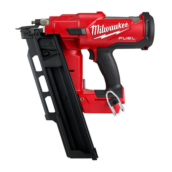
Milwaukee M18 FUEL Service Parts List
5kg sds-max
Hide thumbs
Also See for M18 FUEL:
- Operator's manual (29 pages) ,
- Quick start manual (2 pages) ,
- Operator's manual (8 pages)
Advertisement
EXAMPLE:
00
Component Parts (Small #) Are Included
0
When Ordering The Assembly (Large #).
FIG. PART NO.
DESCRIPTION OF PART
21
43-62-5316
Side Handle Assembly
21a 42-68-5316
Clamping Band
21b 06-54-5316
M8 x 6.5mm Square Nut
32
49a
(9x)
(2x)
49b
50
FIG. PART NO.
DESCRIPTION OF PART
21c 44-40-5316
Clamp Holder
21d 43-98-5316
Side Handle
22a 05-78-5316
M4 x 14mm Pan Hd. Taptite T-20
23
42-36-0019
Belly Shroud
24
14-29-0028
Gearcase Assembly
32
34-40-5308
O-Ring
40
34-40-5320
O-Ring
41
02-04-0009
Ball Bearing
42
45-88-5313
Snap Ring
43
16-10-0045
Service Rotor Assembly
43a ---------------
Retaining Ring
43b ---------------
Rotor
43c 02-04-5382
Ball Bearing
45
14-20-0235
Electronics Assembly
45a ---------------
On-Off Switch
45b ---------------
Stator Assembly
45c ---------------
LED Assembly
45d ---------------
Terminal Block (See Item 55)
45e ---------------
PCBA
46
31-44-0046
Motor Housing Insulator Assembly
46a ---------------
Motor Housing Insulator Halve - Left
46b ---------------
Motor Housing Insulator Halve - Right
46c 06-82-2025
M3.5 x 16mm Pan Hd. ST T-10 Screw
47
06-82-0026
M6.0 x 27mm Pan Hd. Tapt. T-30 Screw
48
42-42-0019
Locking Shuttle
49
31-44-0068
Housing/FUEL™ Logo Assembly
49a 05-78-5311
M5 x 18mm Pan Hd. ST T-20 Screw
49b ---------------
Housing Halve - Right (Cover)
49c ---------------
Housing Halve - Left (Support)
49d ---------------
FUEL™ Logo Plate
50
12-20-0072
Service Nameplate
51
42-55-2717
Blow Molded Carrying case
54
45-06-0052
Rotary Seal
55
22-56-0014
Terminal Block/Housing Service Kit
SERVICE PARTS LIST
SPECIFY CATALOG NO. AND SERIAL NO. WHEN ORDERING PARTS
M18™ FUEL™ 5Kg SDS-Max Rotary Hammer
2717-20
CATALOG NO.
NO. REQ.
(1)
(1)
(1)
45
48
45a
55
45d 49b
45b
49c 50
45d
47
(4x)
46b
46c
(6x)
NO. REQ.
(1)
(1)
(1)
(1)
(1)
(2)
(1)
(1)
(1)
(1)
(1)
(1)
(1)
(1)
(1)
(1)
(1)
(1)
(1)
(1)
(1)
(1)
(6)
(4)
(1)
(1)
(9)
(1)
(1)
(1)
(1)
(1)
(1)
(1)
STARTING
SERIAL NO.
45a 45b 45c
45d 45e
49d
46a
45c
45e
46
46a 46b
46c
40
41
43a
43b
FIG.
NOTE:
45d,55
Terminal Block (45d) is not available
individually and must be ordered in a
Terminal Block/Housing Service Kit (55).
The service kit contains the following parts:
1 --------------- Housing Support
1 --------------
1 --------------
2 --------------
2 --------------
1 12-20-0072 Service Nameplate
1 58-22-0114 Service Instruction Sheet
It is recommended that this kit be installed at a Milwaukee Authorized
Service Station or Factory Service Center.
• See page 2 for the exploded view and parts listing of the
mechanical portion of the tool and service fi xtures.
• See page 3 for lubrication instructions, torques chart,
maintenance instructions and service kits.
• See Page 4 for wiring instructions.
REVISED BULLETIN
WIRING INSTRUCTION
G89A
SEE PAGE 4
= Component of the
14-46-0064
Service Maintenance Kit
49
49a 49b
49c 49d
54
49c
24
42
23
43
43a 43b
43c
21
21a 21b
43c
21c 21d
Housing Cover
Service Terminal Block
4mm dia. x 20mm Shrink Tube
2mm dia. x 20mm Shrink Tube
MILWAUKEE ELECTRIC TOOL CORPORATION
13135 W. Lisbon Road, Brookfi eld, WI 53005
BULLETIN NO.
54-24-2760
DATE
Nov. 2015
21a
51
22a
21b
21c
21d
Drwg. 1
Advertisement
Table of Contents

Summary of Contents for Milwaukee M18 FUEL
- Page 1 Motor Housing Insulator Assembly 1 58-22-0114 Service Instruction Sheet 46a --------------- Motor Housing Insulator Halve - Left It is recommended that this kit be installed at a Milwaukee Authorized 46b --------------- Motor Housing Insulator Halve - Right Service Station or Factory Service Center.
- Page 2 FIG. PART NO. DESCRIPTION OF PART NO. REQ. 31a 31b DO NOT exceed 45-56-5316 Striker Assembly 40 In/Lbs for #29b 31c 31d 19a 45-56-5320 Striker 19b 34-40-5310 O-Ring 29b (2x) 45-88-5314 Washer (2x) 22b 05-78-5316 M4 x 14mm Pan Hd. Taptite T-20 14-29-0028 Gearcase Assembly 14-08-0055...
- Page 3 Doing so will prolong the life of the hammer by reducing wear to gears and mechanism parts. The carbon brushes and armature commutator in this MILWAUKEE Rotary Hammer are designed and matched for many hours of reliable performance.
- Page 4 Locking Shuttle O-Ring (Both sides) On-Off Switch Fuel Logo Plate = WIRE TRAPS Terminal Block or GUIDES AS AN AID TO REASSEMBLY, TAKE NOTICE OF WIRE ROUTING AND POSITION IN WIRE GUIDES AND TRAPS WHILE DISMANTLING TOOL. BE CAREFUL AND AVOID PINCHING WIRES BETWEEN HANDLE HALVES WHEN ASSEMBLING.


Need help?
Do you have a question about the M18 FUEL and is the answer not in the manual?
Questions and answers