Table of Contents
Advertisement
Advertisement
Table of Contents

Related Manuals for Siemens SIMATIC HMI TP900


Summary of Contents for Siemens SIMATIC HMI TP900
- Page 1 Function Manual SIMATIC HMI TP900 Operator Panel Edition 10/2016 www.siemens.com...
-
Page 3: Description
Introduction Safety notes Description Medium-voltage converters Screens SIMATIC TP900 Function Manual Installing software Service & Support Function Manual 10/2016 A5E39487277A... - Page 4 Note the following: WARNING Siemens products may only be used for the applications described in the catalog and in the relevant technical documentation. If products and components from other manufacturers are used, these must be recommended or approved by Siemens. Proper transport, storage, installation, assembly, commissioning, operation and maintenance are required to ensure that the products operate safely and without any problems.
-
Page 5: Table Of Contents
Table of contents Introduction..............................7 About these instructions......................7 Safety notes..............................9 Description..............................11 TP900 operator panel......................11 Screen display areas......................12 Color information ........................15 Setting the screen........................16 Screens..............................17 Overview screen........................17 "Status" screen selection.......................18 4.2.1 "DC Link" screen........................18 4.2.2 "Recooling Unit" screen......................19 4.2.3 "Power Cells" screen......................19 4.2.4 "Drive"... - Page 6 Table of contents TP900 Function Manual Function Manual, 10/2016, A5E39487277A...
-
Page 7: Introduction
Introduction About these instructions These instructions describe the software and functions of the TP900 operator panel and how to work with it. These instruction are valid as of software version 1.9.9.2. Keep these instructions for later use. Read these instructions before you work with the operator panel and follow the instructions. - Page 8 Introduction 1.1 About these instructions TP900 Function Manual Function Manual, 10/2016, A5E39487277A...
-
Page 9: Safety Notes
Safety notes It is essential that you follow all the safety instructions listed in the converter operating instructions, for your own safety, to protect other people and to avoid damage to property. The product/system described in this documentation may only be operated by personnel qualified for the specific task in accordance with the relevant documentation for the specific task, in particular its warning notices and safety instructions. - Page 10 Safety notes TP900 Function Manual Function Manual, 10/2016, A5E39487277A...
-
Page 11: Description
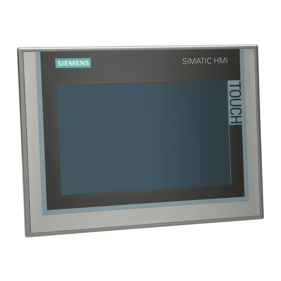
Description TP900 operator panel The converter is operated and diagnosed using the operator panel. Figure 3-1 Operator panel The operator panel communicates with the drive via Ethernet. The operator panel has the following functions: ● Touch-screen operation ● Screen saver ●... -
Page 12: Screen Display Areas
Description 3.2 Screen display areas Screen display areas The operator panel screen is divided into several areas. Not all areas are displayed depending on the function. ① Header ② Configuration of the converter ③ Main contents area ④ Function keys ⑤... - Page 13 Description 3.2 Screen display areas "Configuration of the converter" display This area displays the configuration of the converter. Additional color information is provided for the operating state of the drive. You will find information in Section "Color information". Single-circuit converter Double-circuit converter ①...
- Page 14 Description 3.2 Screen display areas Function keys This area contains the buttons for controlling the operator panel and the converter. The <Local> button switches the converter to local operation. Operator con‐ trol is enabled when the converter is in the "Ready for switch on" status. The status display changes from "0"...
-
Page 15: Color Information
Description 3.3 Color information Button Display Fault/Alarm This button calls the detailed fault and alarm messages of the converter. Local operation This button controls the local operation of the converter. The following functions are available: ● Speed controlled ● Parameters ●... -
Page 16: Setting The Screen
Description 3.4 Setting the screen Setting the screen Press the <Settings> button on the right side of the header. Figure 3-5 Settings The screen is divided into several areas: ● Screen – <Calibrate>: Parallax may occur on the touch screen depending on the mounting position and the viewing angle. -
Page 17: Screens
Screens The following sections contain a description of the screens which you can call in the navigation bar. Overview screen The "Overview" screen displays the following information: ● Actual values of the converter ● The current status of the converter. Calling the screen Press the "Home"... -
Page 18: Status" Screen Selection
Screens 4.2 "Status" screen selection "Status" screen selection 4.2.1 "DC Link" screen The "DC Link" screen displays the following information: ● Actual values of the DC link ● The current status of the pre-charging unit. ● The current status of the transformer ●... -
Page 19: Recooling Unit" Screen
Screens 4.2 "Status" screen selection 4.2.2 "Recooling Unit" screen The "Recooling Unit" screen displays the following information: ● The current values of the cooling system ● The current status of the pumps ● The current status of the deionizer ● The current status of the expansion tank Calling the screen Press the "Status"... -
Page 20: Drive" Screen
Screens 4.2 "Status" screen selection The cell status is displayed as follows: Color Cell status No color Not charged Green Charged Yellow Fault pending Alarm pending Pink Bridged (bypass) Calling the screen Press the "Status" button in the navigation bar. Select the "Power Cells" screen. Figure 4-4 Example: "Power Cells"... -
Page 21: Infeed" Screen
Screens 4.2 "Status" screen selection Figure 4-5 Example: "Drive" screen, single-circuit Further information can be found in the List Manual of the converter, Chapter "PROFIdrive", Section STW1, ZSW1. 4.2.5 "Infeed" screen The "Infeed" screen displays the current status of the control bits. The bit values are displayed as follows: ●... -
Page 22: Temperature" Screen Selection
Screens 4.3 "Temperature" screen selection Figure 4-6 Example: "Infeed" screen, single-circuit "Temperature" screen selection 4.3.1 "Temperature" screen The "Temperature" screen displays the following information: ● All temperatures measured in the converter control cabinet ● Fan status during operation Calling the screen Press the "Temperature"... -
Page 23: Trace" Screen Selection
Screens 4.4 "Trace" screen selection Figure 4-7 Example: "Temperature" screen, double-circuit converter ● When the fan is in operation, the color changes to green. Defective fans are displayed as alarm text ● When the control cabinet temperature is exceeded, the control cabinet color changes to yellow or red. - Page 24 Screens 4.4 "Trace" screen selection Calling the screen Press the <Trace> button in the navigation bar. Figure 4-8 Example: "Trace" screen Selecting values Press the <Setpoints> button. The overview for selecting the trace signals appears. You can select up to eight signals that you want to record. Figure 4-9 Example: Selection of the trace signals TP900 Function Manual...
-
Page 25: Fault/Alarm" Screen Selection
Screens 4.5 "Fault/Alarm" screen selection "Fault/Alarm" screen selection 4.5.1 "Fault/Alarm" screen The "Fault/Alarm" screen displays the following information: ● Faults/alarms are displayed with the fault time, the fault number, the drive object and a fault description. ● An alarm or fault is also displayed in the navigation bar in the "Fault/Alarm" field: –... -
Page 26: Local Operation" Screen Selection
Screens 4.6 "Local Operation" screen selection "Local Operation" screen selection 4.6.1 "Speed control" screen You can change the speed of the motor during local operation in this screen. Note Enabling of the local operation Local operation can only be enabled when the converter is not in operation. Calling the screen Press the <Local operation>... -
Page 27: Parameters" Screen
Screens 4.6 "Local Operation" screen selection Figure 4-12 Example: Communication fault display 4.6.2 "Parameters" screen You can change individual parameters with this screen. The screen is password-protected: ● User: gh ● Password: 150 Note Qualified personnel The "Parameters" screen must only be used for the specific Qualified personnel task. Observe the documentation to be used, particularly regarding the warning and safety instructions. -
Page 28: Expert" Screen
2. Accept the changed value. Press the respective "Take over" button. 4.6.3 "Expert" screen This screen is used for the configuration of the operator panel and for troubleshooting. The "Expert" screen is intended for SIEMENS personnel only and is therefore password-protected. TP900 Function Manual Function Manual, 10/2016, A5E39487277A... -
Page 29: Installing Software
6AV2181-8XP00-0AX0. Order the SD card via the Industry Mall (https:// mall.industry.siemens.com/goos/WelcomePage.aspx?regionUrl=/&language=en). The software for the operator panel is on the CompactFlash card supplied with the converter. If you have to install the software for the operator panel, proceed as follows: 1. - Page 30 Installing software 5.1 Setting up the operator panel TP900 Function Manual Function Manual, 10/2016, A5E39487277A...
-
Page 31: Service & Support
(www.siemens.com/yourcontact) Siemens Support for on the move You can obtain optimum support anywhere you go using the "Siemens Industry Online Support” app. The app is available for Apple iOS, Android and Windows Phone. TP900 Function Manual... - Page 32 Service & Support TP900 Function Manual Function Manual, 10/2016, A5E39487277A...
-
Page 33: Index
Index " ", 16 Language, 16 Local service, 31 Actual values, 18 Main contents area, 13 More information, 31 Brightness, 16 Navigation bar, 14 Cell ID, 19 Cell status, 19 Changing the speed, 26 Operating system, 16 Close, 16 Conductivity, 19 Configuration of the converter, 13 Current status, 18 Runtime, 16... - Page 34 Index TP900 Function Manual Function Manual, 10/2016, A5E39487277A...
- Page 36 Siemens AG Industrie Sector Driver Technoligies and Industry Automation Postfach 48 48 90026 NÜRNBERG Deutschland...