Table of Contents
Advertisement
Quick Links
Advertisement
Table of Contents

Related Manuals for IXXAT CAN@net II


Summary of Contents for IXXAT CAN@net II
- Page 1 CAN@net II Intelligent PC/CAN Interface USER MANUAL ENGLISH...
-
Page 2: Registered Trademarks
Internet: www.hms-networks.de E-Mail: info-ravensburg@hms-networks.de Support For problems or support with this product or other HMS products please request support at www.ixxat.com/support. Further international support contacts can be found on our webpage www.ixxat.com Copyright Duplication (copying, printing, microfilm or other forms) and the electronic distribution of this document is only allowed with explicit permission of HMS Technology Center Ravensburg GmbH. -
Page 3: Table Of Contents
5.1 Technical specifications ............17 5.2 Default Network Settings ............. 18 5.3 Accessories ................18 5.3.1 CAN Bus Termination Resistor ..........18 5.4 Notes on EMC ............... 19 Declaration of Conformity ............20 FCC Compliance ................21 CAN@net II - Manual, V1.7... -
Page 5: Introduction
CAN@net II. As a TCP/IP based PC/CAN interface for standard Windows applications the CAN@net II/VCI is the best choice. It offers with the IXXAT standard Windows driver interface VCI an easy to handle and wide functional interface for Windows applications. The IXXAT tools also use this standard driver interface. -
Page 6: Support
1.3 Support For more information on our products, FAQ lists and installation tips, please refer to the support section of our website (http://www.ixxat.de), which also contains information on current product versions and available updates. If you have any further questions after studying the information on our website and the manuals, please contact our support department. -
Page 7: Installation
Installation 2 Installation 2.1 Software Installation To operate the CAN@net II/VCI interface, a driver is required. This driver is part of the VCI (Virtual CAN Interface), which can be downloaded for free from the HMS website (http://www.ixxat.de). For the installation of the CAN driver VCI under Windows, please refer to the VCI installation manual. -
Page 8: Connections And Indicators
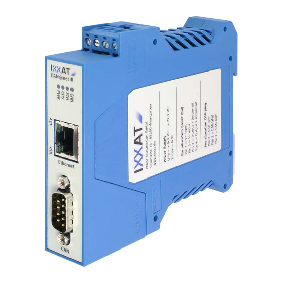
Picture 3-1: Connectors and indicators of the CAN@net II 3.1.1 Power Connector For the power connection of the CAN@net II, a screw terminal is used. For wiring, please ensure that the cross-sectional area of the cable is larger than or equal to 0.14mm². -
Page 9: Ethernet Socket
The Ethernet socket is designed as a standard RJ45 socket. The pin allocation is according to the Ethernet standard. The Ethernet PHY has an auto-crossover feature, so the CAN@net II can be connected with a crossover cable or with a 1-to-1 network cable. -
Page 10: Can Bus Connector
Connections and Indicators 3.1.3 CAN Bus Connector The CAN@net II has a CAN bus interface according to ISO 11898-2. The signals of the CAN bus interface are connected to the Sub D-9 plug (see table 3-1). Pin No. Sub D9... -
Page 11: Power Led (Pwr)
• Device fully functional green Power ok Table 3-4: States of the Power LED 3.2.2 Status LED (CPU) The two-color (green and red) LED indicates the CAN@net II device status. Flashing Description Causes/Hints mode • Boot manager or application firmware... -
Page 12: Ethernet Led (Eth)
3.2.3 Ethernet LED (ETH) The two-color (green and red) LED for Ethernet indicates the Ethernet communication status of the CAN@net II. For each successfully transmitted TCP/IP packet, the LED flashes green. In the case of a transmission error, the LED flashes red. -
Page 13: Link/Data Activity Led (Act)
Warning“ or „Error passive“ state, state the reception/transmission of CAN messages is still possible • The CAN controller is in the „Bus Bus Off Off“ state. No more CAN communication possible Table 3-9: States of the CAN LED CAN@net II - Manual, V1.7... -
Page 14: Can Bus Termination
The configuration tool, which is installed automatically with the VCI, is used to set the network parameters of the CAN@net II. The tool scans the network for CAN@net II devices. The detected devices are shown in the “Device List” and can be configured separately. -
Page 15: Usage
(5) Put the printed board back in the bottom housing. Pay attention to the ESD plastic film, because it has to be assembled. (6) Connect the CAN@net II to the power supply. A green and red running light has to be displayed by the LEDs PWR, CPU, ETH and CAN. - Page 16 Picture 4-2: Position of the DIP switch Switch Position Signal Normal usage (default setting) Resetting of the network parameters to the default settings Unused (default setting) Unused Table 4-1: Functions of the DIP switch CAN@net II - Manual, V1.7...
-
Page 17: Appendix
-40 °C to +85 °C Relative humidity: 10 to 95 %, non-condensing Galvanic isolation: 500 V AC for 1 min Device security: CSA/UL 60950-00 Class 3862 10, 3862 90 Environmental directive: RoHS, WEEE, directive (2002/95/EC) CAN@net II - Manual, V1.7... -
Page 18: Default Network Settings
Table 5-1: Default Network Settings 5.3 Accessories 5.3.1 CAN Bus Termination Resistor HMS offers a bus terminal resistor as a feed through connector (order number 1.04.0075.03000). Picture 5-1: Connections of the CAN bus terminal resistor CAN@net II - Manual, V1.7... -
Page 19: Notes On Emc
Picture 5-2: CAN bus termination resistor 5.4 Notes on EMC The PC/CAN-Interface CAN@net II may only be used with a PC that has a CE- symbol. The CAN-bus connected to the interface must have a shielded lead. The shield braiding must be connected with low impedance to the connector housing. -
Page 20: Declaration Of Conformity
1.01.0086.10200 1.01.0086.10201 1.01.0086.10202 do comply with the EC directives 2004/108/EC. Applied harmonized standards in particular: EN 55022:2006 + A1:2007 EN 61000-6-2:2005 23.08.2011, Dipl.-Ing. Christian Schlegel, Managing Director IXXAT Automation GmbH Leibnizstrasse 15 88250 Weingarten CAN@net II - Manual, V1.7... -
Page 21: Fcc Compliance
Operation of this equipment in a residential area is likely to cause harmful interference, in which case the user will be required to correct the interference at his own expense. CAN@net II - Manual, V1.7... - Page 22 This page intentionally left blank...
Need help?
Do you have a question about the CAN@net II and is the answer not in the manual?
Questions and answers