Table of Contents
Advertisement
Quick Links
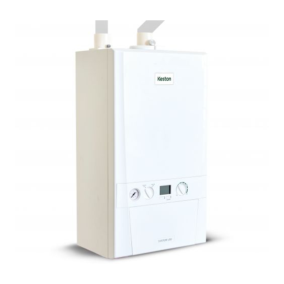
System s30
Installation and Servicing Instructions
FAN POWERED HIGH EFFICIENCY
MODULATING DOMESTIC CONDENSING
GAS SYSTEM BOILER
When replacing any part on this appliance, use only spare parts that you can be
assured conform to the safety and performance specification that we require.
Do not use reconditioned or copy parts that have not been clearly authorised by Keston.
For the very latest copy of literature for specification and maintenance practices visit our website
www.keston.co.uk where you can download the relevant information in PDF format.
August 2016
UIN 215352 A01
Advertisement
Chapters
Table of Contents

Related Manuals for Keston System s30


Summary of Contents for Keston System s30
-
Page 1: Installation And Servicing Instructions
Do not use reconditioned or copy parts that have not been clearly authorised by Keston. For the very latest copy of literature for specification and maintenance practices visit our website www.keston.co.uk where you can download the relevant information in PDF format. - Page 2 ERP DATA MODEL SYMBOL UNITS Condensing Boiler Low Temperature Boiler B1 Boiler Cogeneration Space Heater Equipped with a Supplementary Heater Combination Heater Nominal Heat Output for Space Heating Full Load Part Load Auxiliary Electricity Consumption Full Load 0.048 Part Load 0.013 Standby 0.005...
-
Page 3: Control Of Water Temperature
PRODUCT FICHE KESTON SYSTEM S BOILER Keston Heating ERP DATA SYMBOL UNITS MODEL Condensing boiler Seasonal Space heating efficiency class Rated heat output ƞ Seasonal space heating energy efficiency Annual energy consumption 93.0 Sound power level, indoors Seasonal Space Heating Energy Efficiency of the Boiler... - Page 4 Installation and Servicing...
- Page 5 To restart the boiler press the RESTART button. The boiler will repeat the ignition sequence if a heat demand is present. DOCUMENT AMENDMENTS Relevant Installation changes implemented in this book from Mod Level ........A01 (Aug 16) Keston reserve the right to vary specification without notice Installation and Servicing...
- Page 6 Installation and Servicing...
-
Page 7: Table Of Contents
Safety Relief Valve Replacement ....... 48 Flue System ............... 18 3.22 Pump Automatic Air Vent Replacement ..... 48 Flue Installation Example Keston System S 30 ..20 3.23 Pump Head Replacement .......... 49 Flue Installation Example Keston System S 30 ..20 3.24... -
Page 8: General
SECTION 1 - GENERAL Table 1 - General Data Gas supply 2H - G20 - 20mbar Gas Supply Connection 15mm copper compression Injector Size (mm) 4.65 Flow Connection Central Heating 22mm copper compression Return Connection Central Heating 22mm copper compression Flue Terminal Diameter mm (in) 50 (2) - Page 9 SECTION 1 - GENERAL Keston System S Natural Gas only Boiler size G.C. Appliance No. PI No. (Benchmark No.) 41-930-45 86 CR 18 Destination Country: GB, IE For GB, to comply with Building Regulations Part L1 (Part 6 in Scotland) the boiler should be fitted in accordance with the manufacturer’s instructions.
-
Page 10: Introduction
1.3 SAFE HANDLING This boiler may require 2 or more operatives to move it to its The Keston System S boiler is wall mounted, full sequence, installation site, remove it from its packaging base and during automatic spark ignition, low water content, fanned flue, high movement into its installation location. -
Page 11: Safety
In both cases, details of essential features of cupboard / compartment design, including airing cupboard installation, are to Any direct connection of a control device not approved by Keston conform to the following: could invalidate the certification and the normal appliance warranty. -
Page 12: Gas Supply
BS6891:2005. Whilst of temperature in individual rooms should also be fitted with a the principle of the 1:1 gas valve ensures the Keston range is room thermostat controlling the temperature in a space served by able to deliver it’s full output at inlet pressures as low as 14mb,... -
Page 13: Boiler Dimensions, Services & Clearances
SECTION 1 - GENERAL 1.13 BOILER DIMENSIONS, SERVICES & CLEARANCES all dimensions in mm The boiler connections are made on the boiler connection tails. Refer to Section 2.13. where wall thicknesses do not exceed 600mm (24”). Where the space into which the boiler is going to be installed is The following minimum clearances must be maintained for less than the length of flue required the flue must be fitted operation and servicing. -
Page 14: System Requirements
SECTION 1 - GENERAL 1.14 SYSTEM REQUIREMENTS - Central Heating Notes a. The method of filling, refilling, topping up or flushing sealed primary hot water circuits from the mains via a temporary hose connection Safety valve setting is only allowed if acceptable to the local water authority. Vessel charge pressure 0.5 to 0.75 b. -
Page 15: System Balancing
Heating Systems. The Heath Business & Technical Park Runcorn Cheshire WA7 4QX If water treatment is used Keston recommend only the use of Tel: 0800 389 4670 SCALEMASTER GOLD 100, FERNOX, MBI, ADEY MC1, SENTINEL www.sentinel-solutions.net inhibitors and associated water... -
Page 16: Boiler Assembly - Exploded View
SECTION 1 - GENERAL 1.17 BOILER ASSEMBLY - Exploded View Note that item numbers are linked to the spares list CH RETURN VALVE GAS VALVE ELECTRODE IGNITION CH FLOW VALVE PIPE - GAS INJECTOR ELECTRODE DETECTION PUMP HEAD INJECTOR ASSEMBLY IGNITER UNIT PUMP AUTO AIR VENT VENTURI... -
Page 17: Unpacking
SECTION 1 - GENERAL 1.18 UNPACKING Unpack and check the contents. Pack A Contents Boiler Hardware Pack Box Wall Mounting Plate These Installation/Users Instructions Wall Mounting Template (located on internal protective packaging) Safety Valve Drain Pipe Boiler Guarantee & Registration Pack Boiler Guarantee HARDWARE PACK CONTENTS Gas Valve Pack... -
Page 18: Installation
SECTION 2 - INSTALLATION 2.1 FLUE SYSTEM When installing a replacement boiler a new flue system must The following pipes and fittings are approved: be used. DO NOT re-use the existing boiler flue installation. Polypipe System 2000 muPVC solvent Weld Waste System (50mm) DESIGN Poly Pipe Code... - Page 19 A 92.5º swept elbow is equivalent to 1.0m straight length. A 45º bend is equivalent to 0.5m straight length. It is possible to have variable flue and air lengths as described within the shaded area of graph below. Keston System 30 - Flue & Air Pipe Length Acceptable Operating Area...
-
Page 20: Flue Installation Example Keston System S 30
SECTION 2 - INSTALLATION 2.2 FLUE INSTALLATION EXAMPLE KESTON SYSTEM S 30 Keston System 30 - Flue & Air Pipe Length 15.5 1.5º back to boiler Bracket at each 1 metre 10.15 1.5m 0.15m Acceptable Operating Area 8 10 12 14 16 18 20 22 24 26 28 30 1.5º... -
Page 21: Flue Termination Position
The boiler casing must always be correctly fitted to the boiler when leaving the appliance operational. External wall faces and any internal faces of cavity walls must be good. AIR SUPPLY The Keston Combi is a room-sealed appliance and therefore does not require purpose provided ventilation to the boiler room for combustion air. COMPARTMENT INSTALLATION Due to the low casing temperatures generated by the boiler, no compartment ventilation is required. -
Page 22: Installing The Boiler
SECTION 2 - INSTALLATION 2.5 INSTALLING THE BOILER Installation of the boiler is straightforward but consideration must be given to access to allow flue and air pipes to be pushed through walls and ceilings. The order in which the components are installed will depend upon particular site conditions, but in general it will be easiest and most accurate to install the boiler and then build up the flue outlet and air inlet pipes to the terminal - this is the sequence described. -
Page 23: Fitting The Wall Mounting Plate
SECTION 2 - INSTALLATION 2.8 FITTING THE WALL MOUNTING PLATE Screw the wall mounting plate to the wall using 2 wall plugs (previously fitted) with the 2 screws provided. Choose one of the 2 sets of slots in left and right bank. Ensuring that at least one of the screws is fitted into a top slot. Example of fixing 3G9948 2.9 MOUNTING THE BOILER... -
Page 24: Assembly Practice
SECTION 2 - INSTALLATION 2.10 ASSEMBLY PRACTICE • Assemble, using solvent weld cement, the pipework from Remove all plastic debris and burrs when installing air intake the boiler connections to the exit from the first wall/ceiling, piping. Plastic fillings caused by cutting muPVC pipe must (remount the boiler if removed). -
Page 25: Fitting The Sleeving
SECTION 2 - INSTALLATION 2.11 FITTING THE SLEEVING 1. Cut hole in wall. 2. Measure wall Thickness 3. Cut sleeve length to match wall thickness & remove burrs. 4. Grout sleeve into wall with flange on external face. 5. Slide flue pipe into sleeve, checking it is free to slide. 6. -
Page 26: Condensate Drain
SECTION 2 - INSTALLATION 2.12 CONDENSATE DRAIN Condensate Pump Where gravity discharge to an internal termination is not physically Condensate possible or where very long internal pipe runs would be required Drain to reach a suitable discharge point, a condensate pump of a specification recommended by the boiler or pump manufacturer should be used terminating into a suitable internal foul water discharge point such as an internal soil and vent stack or internal... - Page 27 SECTION 2 - INSTALLATION CONT’D..Figure 3 - Connection of a Condensate Pump Typical Figure 4 - Connection of condensate Drainage Pipe to Method (see manufacturers detailed instructions) External Soil & Vent Stack Boiler Water/weather Visible air break with 75mm proof insulation Boiler sealed...
-
Page 28: Connections & Filling
SECTION 2 - INSTALLATION 2.13 CONNECTIONS & FILLING NOTES. Ensure all boss blanking plugs are removed before connecting hardware. Each valve must be fitted to the correct boss as shown in the picture. Ensure each union is fitted with fibre seals provided. Do not subject any of the isolating valves to heat as the seals may be damaged. -
Page 29: Electrical Connections
2.15 INSTALLER WIRING The Keston System S boiler comes pre-fitted with 1.8m of All of the connections can now be readily accessed, the plugs can mains cable. This must be connected to a permanent live be removed to aid wiring. - Page 30 MAINS IN CH ON TIMER HW ON HW OFF Note. If an outside sensor is connected, then see diagram below KESTON SYSTEM S BOILER WITH Y PLAN SYSTEM & OUTSIDE SENSOR KIT Y PLAN FUSED VALVE SPUR BOILER SL 2...
-
Page 31: Replacing Pre-Fitted Mains Cable
SECTION 2 - INSTALLATION 2.16 REPLACING PRE-FITTED MAINS CABLE If it is necessary to use an alternative mains cable to the one pre-fitted then use the following guide. Replacement wiring should comply with notes in Section 2.18 and be caried out by a qualified person to avoid a hazard. 1. -
Page 32: External Electrical Controls
SECTION 2 - INSTALLATION 2.18 EXTERNAL ELECTRICAL CONTROLS EXAMPLE - Connection to Honeywell Evohome Wiring External to the Boiler The fuse rating should be 3A. Wiring external to the boiler MUST be in accordance with the current I.E.E. (BS.7671) Wiring Regulations and any local regulations. Frost Protection If parts of the pipework run outside the house or if the boiler will be left off for more than a day or so then a frost thermostat should be wired... -
Page 33: Wiring Diagram
SECTION 2 - INSTALLATION 2.20 WIRING DIAGRAM Installation and Servicing... -
Page 34: Commissioning And Testing
SECTION 2 - INSTALLATION 2.21 COMMISSIONING AND TESTING B. Gas Installation A. Electrical Installation 1. The whole of the gas installation, including the meter, 1. Checks to ensure electrical safety should be carried out by a should be inspected and tested for tightness and purged in competent person. -
Page 35: Initial Lighting
SECTION 2 - INSTALLATION 2.22 INITIAL LIGHTING Legend A. Central Heating Temperature Knob BOILER BOILER B. Mode Knob C. Boiler Status ºC D. Burner ‘on’ indicator E. Central Heating Economy Setting CH Flow Isolating Valve G. System Pressure Gauge RESTART H. -
Page 36: General Checks
SECTION 2 - INSTALLATION 2.23 GENERAL CHECKS Make the following checks for correct operation: CENTRAL HEATING (CH) MODE WATER CIRCULATION SYSTEM 1. Ensure that the CH external controls are 1. With the system COLD, check that the initial pressure is correct to the calling for heat. -
Page 37: Accessing The Installer Mode
SECTION 2 - INSTALLATION 2.25 ACCESSING THE INSTALLER MODE 5. “dU” will be shown To access Installer Mode press the function button and “RESTART” press the Function button Buttons together for more than 5s. 6. “P1” will be shown 1. The last 3 faults will be shown To set the minimum CH pump speed to 100% press “RESTART”, See Section 4.1 for Fault Code descriptions otherwise press the function button. -
Page 38: Servicing
SECTION 3 - SERVICING 3.1 SERVICING SCHEDULE For the very latest copy of literature for specification & maintenance practices, visit our website www.keston.co.uk, where you will be able to download the relevant information. . WARNING. Always turn OFF the gas supply at the gas service cock, and switch OFF and disconnect the electricity supply to the appliance before servicing. -
Page 39: Boiler Front Panel Removal / Replacement
SECTION 3 - SERVICING 3.2 BOILER FRONT PANEL REMOVAL / REPLACEMENT REMOVAL REPLACEMENT 1. Loosen the two screws retaining the front panel. 3. Hook the panel onto the top retaining clips. 2. Pull the two clips down to disengage and pull panel forward 4. -
Page 40: Burner Removal And Cleaning
SECTION 3 - SERVICING 3.4 BURNER REMOVAL AND CLEANING 1. Ensure the sump is fully drained. Refer to Section 3.17. 2. Undo the two screws and remove the sump cover retaining the lower flue manifold. 3. Lift the manifold to clear the bottom sealing gasket and remove manifold. -
Page 41: Cleaning The Heat Exchanger
SECTION 3 - SERVICING 3.6 CLEANING THE HEAT EXCHANGER Note: Ensure the condensate trap/siphon is fully drained before cleaning. Refer to Ignition Electrode Flame Detection Section 3.17. 1. Remove ignition and flame detection electrodes. Refer to Sections 3.13 & 3.14. 2. -
Page 42: Replacement Of Components
SECTION 3 - SERVICING 3.8 REPLACEMENT OF COMPONENTS GENERAL IMPORTANT. When work is complete, the front panel must be correctly When replacing ANY component refitted - ensuring that a good seal is made. 1. Isolate the electricity supply. Notes. 2. Turn off the gas supply. 1. -
Page 43: Burner Injector Replacement
SECTION 3 - SERVICING 3.10 BURNER INJECTOR REPLACEMENT 1. Refer to Section 3.8. 2. Disconnect the electrical leads from the fan. 3. Remove the clip from the gas valve to venturi pipe and ease the pipe upwards, rotate and ease down to remove. 4. -
Page 44: Return Thermistor Replacement
SECTION 3 - SERVICING 3.12 RETURN THERMISTOR REPLACEMENT 1. Refer to Section 3.8. 2. Unclip the return thermistor from the return pipe and withdraw it from the boiler. 3. Disconnect the electrical leads from the thermistor. 4. Reconnect the electrical lead to the new thermistor and reassemble in reverse order, ensuring that the thermistor is securely fitted to the pipe on the thermistor locator tab as shown. -
Page 45: Flame Detection Electrode Replacement
SECTION 3 - SERVICING 3.14 FLAME DETECTION ELECTRODE REPLACEMENT 1. Refer to Section 3.8. 2. Remove the burner. Refer to Section 3.11. Flame Detection Electrode 3. Unplug the flame detection lead from the electrode. 4. Remove the 2 screws retaining the detection electrode. -
Page 46: Gas Control Valve Replacement
SECTION 3 - SERVICING 3.16 GAS CONTROL VALVE REPLACEMENT 1. Refer to Section 3.8. 2. Unplug the electrical lead connection from the gas control valve. 3. Remove the outlet gas valve clip and slide the pipe upwards 4. Undo the gas inlet pipe union at the inlet to the gas valve. -
Page 47: Pcb Replacement
SECTION 3 - SERVICING 3.18 PCB REPLACEMENT Note. Fit the earth strap provided with the PCB to your wrist and secure to a suitable earth on the boiler chassis. 1. Refer to Section 3.8. 2. Ensure the control knobs are in the 12 o clock position. 3. -
Page 48: Pressure Gauge Replacement
SECTION 3 - SERVICING 3.20 PRESSURE GAUGE REPLACEMENT 1. Refer to Section 3.8. 2. Drain the heating system. Refer to Section 3.19. 3. Remove the boiler front (See Section 3.2), lower the control panel and remove the control box cover. 4. -
Page 49: Pump Head Replacement
SECTION 3 - SERVICING 3.23 PUMP HEAD REPLACEMENT 1. Refer to Section 3.8. 2. Drain the boiler. Refer to Section 3.19. 3. Disconnect the two electrical leads from the pump. 4. Remove the 4 Allen screws retaining the pump head. 5. -
Page 50: Heat Engine Replacement
SECTION 3 - SERVICING 3.26 HEAT ENGINE REPLACEMENT Refer also to Section 2.1 - ‘Boiler Exploded View’ IMPORTANT Before starting the removal procedure, protect the gas and electrical controls with a waterproof sheet or plastic bag. 1. Refer to Section 3.8. 12. -
Page 51: Expansion Vessel Recharging & Replacement
SECTION 3 - SERVICING 3.27 EXPANSION VESSEL RECHARGING & REPLACEMENT RECHARGING 1. Remove the charge point cover. Recharge 2. Recharge the tank pressure to 0.75 bar. Point 3. Re-assemble in reverse order 4. Check operation of the boiler. Refer to Sections 2.22 &... -
Page 52: Fault Finding
SECTION 4 - FAULT FINDING 4.1 FAULT FINDING CHART MAIN MENU In order to assist fault finding the boiler has a 7 segment display. The key to the display codes is as follows: GO TO SECTION 4.2 - ‘L1’ FLOW TEMPERATURE OVERHEAT LOCKOUT or NO WATER FLOW LOCKOUT GO TO SECTION 4.3 - ‘L2’... -
Page 53: L1'-Flow Temp Ov'heat Lockout/No Water Flow Lockout
SECTION 4 - FAULT FINDING 4.2 ‘L1’ - FLOW TEMPERATURE OVERHEAT LOCKOUT OR NO WATER FLOW LOCKOUT Is the Boiler and CH System filled with water and all Fill and vent the system and open all isolation and radiator valves open? isolation valves, then restart boiler If the PCB has been replaced check a BCC has been fitted then restart the boiler. -
Page 54: L6' - False Flame Lockout
SECTION 4 - FAULT FINDING 4.4 ‘L6’ - FALSE FLAME LOCKOUT Check routing and integrity of internal boiler Restart the boiler, does Boiler Work OK? wiring is OK. Check condition of Flame Sense Electrode and replace if deteriorated. Separate the flame detection electrode in-line Replace Flame Detection Electrode connector. -
Page 55: L4' Or 'F4' - Control / No Flow Thermistor Fault
SECTION 4 - FAULT FINDING 4.8 ‘L4’ OR ‘F4’ - CONTROL / NO FLOW THERMISTOR FAULT Fit a new Thermistor Remove the Control/No Flow Thermistor from the Heat Exchanger and disconnect the wires. Check the resistance using a suitable multimeter connected across the thermistors terminal pins. -
Page 56: No Ch Operation
SECTION 4 - FAULT FINDING 4.11 NO CH OPERATION Move the mode knob to the ON position Is the mode knob in the ON position? Switch the Timer, Room Stat and Cylinder Stat On Are the Timer and the Room Thermostat or cylinder thermostat switched on? Open the Radiator Valves Are the Radiator Valves Open? -
Page 57: Spare Parts
When replacing any part on this appliance use only spare parts that you can be assured conform to the safety and performance specification that we require. Do not use reconditioned or copy parts that have not been clearly authorised by Keston. Failure to do so could affect safety or performance of this appliance. -
Page 59: Benchmark & Commissioning
Benchmark Commissioning and Servicing Section It is a requirement that the boiler is installed and commissioned to the manufacturers instructions and the data fields on the commissioning checklist completed in full. To instigate the boiler guarantee the boiler needs to be registered with the manufacturer within one month of the installation. -
Page 60: Gas Boiler System Commissioning Checklist
GAS BOILER SYSTEM COMMISSIONING CHECKLIST This Commissioning Checklist is to be completed in full by the competent person who commissioned the boiler as a means of demonstrating compliance with the appropriate Building Regulations and then handed to the customer to keep for future reference. CONTROLS Programmable room thermostat Optimum start control... -
Page 61: Service Record
SERVICE RECORD It is recommended that your heating system is serviced regularly and that the appropriate Service Interval Record is completed. Service Provider SERVICE 01 SERVICE 02 ² % ² % ² % ² % (Where Possible) (Where Possible) Signature Signature SERVICE 03 SERVICE 04... - Page 62 FLOWCHART FOR CO LEVEL AND COMBUSTION RATIO CHECK ON COMMISSIONING A CONDENSING BOILER Important Preliminary Information on Checks The air gas ratio valve is factory-set and must not be adjusted DURING COMMISSIONING. If the boiler requires conversion to operate with a different gas family (e.g. conversion from natural gas to LPG) sepa- rate guidance is provided with the conversion kit supplied and this must be followed.
- Page 63 Start Set Boiler to Maximum Gas Rate Carry Out Flue Integrity Check Using Analyser In accordance with boiler instructions, Insert analyser probe into air inlet test point (where available) and allow set boiler to operate at maximum rate readings to stabilise. (full load condition).
- Page 64 Keston Heating, PO Box 103, National Avenue, Kingston Upon Hull, HU5 4JN Tel. +44 (0) 1482 443005 Fax. +44 (0) 1482 467133. www.keston.co.uk K e s t o n p u r s u e s a p o l i c y o f c o n t i n u i n g i m p r o v e m e n t i n t h e d e s i g n a n d p e r f o r m a n c e o f i t s p r o d u c t s .
-
Page 65: User Guide
Do not use reconditioned or copy parts that have not been clearly authorised by Keston. For the very latest copy of literature for specification and maintenance practices visit our website... - Page 66 INTRODUCTION CONTENTS The Keston System S is a system boiler, featuring full sequence automatic spark ignition and fan assisted combustion. It is 1. Introduction .............. 2 designed to provide central heating and hot water when a separate hot water cylinder is installed.
-
Page 67: Boiler Operation
BOILER OPERATION Legend A. CH temperature control B. Mode Control Knob C. Boiler Status BOILER BOILER D. Burner ‘on’ indicator E. Function Button ºC F. Restart Button G. Pressure Gauge H. Central Heating Economy Setting RESTART TO START THE BOILER EFFICIENT HEATING SYSTEM OPERATION If a programmer is fitted refer to separate instructions for the The boiler is a high efficiency, condensing appliance which will... -
Page 68: Condensate Drain
CONDENSATE DRAIN GENERAL INFORMATION This appliance is fitted with a siphonic condensate trap system BOILER PUMP that reduces the risk of the appliance condensate from freezing. The boiler pump will operate briefly as a self-check once every 24 However should the condensate pipe to this appliance freeze, hours, regardless of system demand. -
Page 69: Points For The Boiler User
Registered Engineer or in IE a Registered Engineer or in IE a Registered Gas Installer (RGII) Registered Gas Installer (RGII) FOR ANY QUERIES PLEASE RING THE KESTON CONSUMER HELPLINE : 01482 498660 NOTE. BOILER RESTART PROCEDURE - To restart boiler, press the “RESTART” button. User’s... -
Page 70: Normal Operation Display Codes
NORMAL OPERATION DISPLAY CODES DESCRIPTION DISPLAY CODE ON BOILER The boiler is in standby operation awaiting either a central heating call or hot water demand. The boiler has a call for central heating but the appliance has reached the desired temperature set on the boiler. -
Page 71: Fault Codes
(RGII). Fan Fault Restart the appliance - if the boiler fails to operate then please contact Keston (if under warranty) or alternatively a Gas Safe Registered Engineer if outside of the warranty period. In IE contact a Registered Gas Installer (RGII). - Page 72 Check system pressure is between 1 & 1.5bar on the pressure gauge (if fitted Flow Temperature Overheat to a sealed system). If the boiler fails to operate then please contact Keston (if under warranty) or alternatively a Gas Safe Registered Engineer if outside Unconfigured PCB of the warranty period.
Need help?
Do you have a question about the System s30 and is the answer not in the manual?
Questions and answers