Table of Contents
Advertisement
WD265/0/2002
Fan Powered High Efficiency
Modulating Domestic Condensing Gas Boiler
Installation And Servicing Instructions
C40, C40P, C55 & C55P Models
These instructions must be left either with
the user or next to the site gas meter.
Tel. +44 (0)20 8462 0262 Fax. +44 (0)20 8462 4459
email : info@keston.co.uk web : www.keston.co.uk
COMPLIANT WITH BUILDING REGULATION PART L1 & L2 2002
CE/PI No : 87BN14
C40 - GC No : 41-930-07
C40P - GC No : 41-930-08
C55 - GC No : 41-930-09
C55P - GC No : 41-930-10
34 West Common Road
Hayes, Bromley, Kent BR2 7BX
SEDBUK A RATED
The Keston C40, C40P, C55 & C55P
Advertisement
Table of Contents

Related Manuals for Keston C40


Summary of Contents for Keston C40
-
Page 1: Installation And Servicing Instructions
WD265/0/2002 The Keston C40, C40P, C55 & C55P Fan Powered High Efficiency Modulating Domestic Condensing Gas Boiler Installation And Servicing Instructions C40, C40P, C55 & C55P Models CE/PI No : 87BN14 C40 - GC No : 41-930-07 C40P - GC No : 41-930-08... -
Page 2: Table Of Contents
WD265/0/2002 The Keston C40, C40P, C55 & C55P CONTENTS Section Description HANDLING INSTRUCTIONS List of contents Recommended handling procedure GENERAL INSTRUCTION Description Boiler Schematic Related Documents Physical Data Performance Data C40 and C40P Performance Data C55 and C55P Optional Accessories BOILER LOCATION Dimensions &... - Page 3 WD265/0/2002 The Keston C40, C40P, C55 & C55P COMMISSIONING OF THE BOILER Initial Flushing Gas Supply Electrical Installation LP Gas Initial Firing Hot Flushing Combustion Testing Checking The Gas Pressure Timing The Gas Meter 4.10 Handing Over To The User...
-
Page 4: Recommended Handling Procedure
0. HANDLING INSTRUCTION LIST OF CONTENTS The Keston C40 and C55 are supplied almost totally pre-assembled. Since the units use standard 50 mm muPVC pipe for the flue and air intake systems the boiler is packed in a single box without additional flue kit. All additional components are packed inside the boiler cabinet itself. - Page 5 Safety footwear and gloves are recommended PPE when lifting this appliance. The C40 and C55 boilers can be fitted in compartments with very small clearances required around the appliance (refer to Section 1.4). Due consideration should therefore be given to access within the compartment for lifting and positioning.
-
Page 6: Description
11kW to 40kW (C40 & C40P) and 14kW to 55kW (C55 & C55P). The integral Grundfos pump is automatically controlled to best match water flow rate to heat output &... -
Page 7: Related Documents
The C40 and C55 feature an integral frost protection function which will operate the pump, regardless of the external controls, should the boiler temperature fall below 7 C. -
Page 8: Physical Data
Keston Boilers Ltd declare that there are no substances harmful to health within the appliance or used during the production of the appliance. The C40 and C55 are intended for domestic and commercial EMC environments and on a governed G20 meter supply. -
Page 9: Performance Data: C40&C40P/C55&C55P
WD265/0/2002 Chapter 1 : General Instruction The Keston C40, C40P, C55 and C55P PERFORMANCE DATA - C40 & C40P C40P Nat. Gas (G20) LPG (G31) Min. Input (Gross CV) kW/(Btu/h) 12.9/(43,900) 12.6/(43,000) Max. Input (Gross CV) kW/(Btu/h) 45.6/(155,600) 43.2/(147,400) Max. Output To Water... -
Page 10: Optional Accessories
BENCHMARK INITIATIVE As part of the industry wide “Benchmark” initiative C40 & C55 boilers manual includes Gas Boiler Commissioning Checklist (Chapter 9). This form should be completed by your installer at the end of the installation and commissioning process. The details of the Checklist will be required in the event of any warranty work being required. -
Page 11: Dimensions & Minimum Clearances
See Section 1.5 - Optional Accessories. Figure 2.1.2 Dimensions All dimensions in mm. POSITION The C40 and C55 are not suitable for Air Intake external installation. The boiler may be installed in any room or internal space, Flue although particular attention is drawn... - Page 12 Chapter 2 - Boiler Location The Keston C40, C40P, C55 & C55P the bath or shower. The C40 and C55 are classified as IP20 (IPX0) and are therefore suitable for installation in Zone 3 areas, unless subject to hose down.
-
Page 13: Boiler Size Selection
2.4.4 Wiring Expample - Honeywell S-Plan for DHW and (Optional) Weather Compensated Heating Control BOILER SIZE SELECTION The C40 and C55 will automatically adjust heat output and pump speed to match the system requirements at any given time. Efficiency and combustion levels are maintained at optimum levels throughout the possible output range. -
Page 14: Water Systems
Chapter 2 - Boiler Location The Keston C40, C40P, C55 & C55P the length of run from the meter to the boiler at a supply rate of 46kW for the C40 and 57kW for the C55 model. A gas cock is supplied loose with the boiler. This cock should be fitted in the gas line to the boiler as close to the boiler as possible so that it is easily identified as the cock to isolate the boiler. - Page 15 Where thermal stores are to be used the thermal store supplier should be consulted as to the compatibility of the thermal store with a Keston C40 and C55. Thermal store units where the boiler directly heats an open vented thermal store are not suitable for use with the C40 or C55.
- Page 16 1394. It is advisable to fit a locksheild valve on the cylinder return to enable balancing of the flow rate through the cylinder. The Keston Spa range of stainless steel unvented cylinders are an ideal option for use with the Keston range. The Keston Spa range combine Installation &...
- Page 17 WD265/0/2002 Chapter 2 - Boiler Location The Keston C40, C40P, C55 & C55P exceptional recovery times with durable, long life stainless steel construction and all associated controls. Contact Keston Boilers Ltd for information 2.7.4 Boiler By-pass Piping Boiler water flows are critical to the operation of the boiler. If flow cannot be maintained through the system piping to meet the minimums required by the boiler, insufficient water flows through the boiler will cause the boiler to "kettle"...
-
Page 18: Flue System
WD265/0/2002 Chapter 2 - Boiler Location The Keston C40, C40P, C55 & C55P bubbles can interfere with pumping and heat transfer and must be eliminated. Installation of air bleed valves at the high spot(s) in the system will allow for air elimination when filling the system and will allow re-venting in a day or so after all air has been driven out of solution. - Page 19 WD265/0/2002 Chapter 2 - Boiler Location The Keston C40, C40P, C55 & C55P 2.8.2 Maximum Lengths The maximum lengths of both air inlet pipe and flue outlet pipe, when no bends are used, are as detailed below. 50mm 75mm Maximum Air Inlet Length 29.0 m...
- Page 20 WD265/0/2002 Chapter 2 - Boiler Location The Keston C40, C40P, C55 & C55P entering the pipe. There must Figure 2.8.3 : be no troughs in any of the Flue Condensate Drain pipework, whether it be air Point Example inlet or flue outlet.
-
Page 21: Compartment Installation
2.11 CONDENSATE DRAINAGE Being a condensing boiler, the C40 and C55 are fitted with a condensate trap at the base of the heat exchanger and flue assembly, with facility to connect to a drain point underneath the appliance. -
Page 22: Wall Mounting Bracket
WD265/0/2002 Chapter 3 : Installation The Keston C40, C40P, C55 & C55P 3. INSTALLATION OF THE BOILER Read Chapter 2 - Boiler Location and decide upon the position of the boiler. Installation of the boiler is straightforward but consideration must be given to access to allow flue and air pipes to be pushed through walls and ceilings. -
Page 23: Water System
WD265/0/2002 Chapter 3 : Installation The Keston C40, C40P,C55 & C55P Remember the flue pipe must slope downwards back towards the boiler and this is best achieved using 92.5 bends. Using the template supplied within the boiler packaging mark the positions of the two holes for the flue and air pipes on the wall(s) or ceiling. -
Page 24: Gas Supply
WD265/0/2002 Chapter 3 : Installation The Keston C40, C40P, C55 & C55P For optimum performance after installation, this boiler and its associated central heating system must be flushed in accordance with the guidelines given in BS7592:1992, "Treatment of water in domestic hot water central heating systems". - Page 25 It is essential that sludge or scale is removed from an existing system. The guarantee provided with the Keston C40 and C55 does not cover damage caused by system debris or sludge. Connect the new boiler as instructed in this manual and fit in accordance with Sections 3.1 to 3.8...
-
Page 26: Commissioning Of The Boiler
INITIAL FLUSHING All waterways within the Keston C40 and C55 are either copper, high alloy stainless steel or aluminium. As a result water treatment chemicals for central heating boilers such as Fernox MB1, Sentinel X100 or equivalent, are suitable. -
Page 27: Combustion Testing
) levels will be between 8 & 8.2% (C40 low rate), 8.3 & 8.5% (C55 low rate), 8.2 & 8.7% (C40 high rate) and 8.6 & 9% C55 (high rate) and carbon oxide (CO) levels will be between 5 to 20 ppm (low rate) and 50 to 150 ppm (high rate) for natural gas. For LP gas, carbon dioxide (CO ) levels will be between 9.3 &... -
Page 28: Checking The Gas Pressure
8% to 8.2% for C40 and 8.3% to 8.5% for C55 with a corresponding CO level of 5 to 20 ppm for natural gas and 9.3% to 9.5% for C40P and 9.6% to 9.8% for C55P with a corresponding CO level of 5 to 20 ppm for LPG. - Page 29 WD265/0/2002 Chapter 4 : Commissioning The Keston C40, C40P, C55 & C55P If all joints are sound and the gas inlet pressure is satisfactory check the gas input by timing the gas meter as detail in Section 4.9 Timing The Gas Meter.
-
Page 30: Fault Finding
WD265/0/2002 Chapter 5 : Fault Finding The Keston C40, C40P, C55 & C55P 5. FAULT FINDING ELECTRICAL CONTROL SEQUENCE When the external controls are calling for heat, power will be fed to the boiler connection strip at terminals SL1 (Switched Live 1) &/or SL2 (Switched Live 2) and N (Neutral). If the user control setting on the relevant knob is to a temperature less than the boiler flow temperature the display will show “6 nn”... -
Page 31: Normal Operation
QUICK REFERENCE NORMAL OPERATION The C40 and C55 boilers feature a user display which shows actual flow temperature at all times (the last two digits of the display) and a status number (the first digit) which identifies what the boiler is doing at any given time. The table below shows the range of status codes which will be... -
Page 32: Lockout
WD265/0/2002 Chapter 5 : Fault Finding The Keston C40, C40P, C55 & C55P 5.3.2 LOCKOUT If the fault is persistent or more severe the boiler will lockout with a error code. When the boiler has entered this error mode it will not attempt to restart until the “Reset” button is pressed. - Page 33 WD265/0/2002 Chapter 5 : Fault Finding The Keston C40, C40P, C55 & C55P FUNCTIONAL FLOW WIRING DIAGRAM Installation & Servicing Instructions Page : 28...
- Page 34 WD265/0/2002 Chapter 5 : Fault Finding The Keston C40, C40P, C55 & C55P ELECTRICAL WIRING DIAGRAM Installation & Servicing Instructions Page : 29...
- Page 35 WD265/0/2002 Chapter 5 : Fault Finding The Keston C40, C40P, C55 & C55P ILLUSTRATED WIRING DIAGRAM Installation & Servicing Instructions Page : 30...
- Page 36 WD265/0/2002 Chapter 5 : Fault Finding The Keston C40, C40P, C55 & C55P Exploded Assembly Diagrams 5.7.1 Boiler Controls Assembly Installation & Servicing Instructions Page : 31...
- Page 37 WD265/0/2002 Chapter 5 : Fault Finding The Keston C40, C40P, C55 & C55P 5.7.2 Waterway, Condensate & Flue Assembly Installation & Servicing Instructions Page : 32...
- Page 38 WD265/0/2002 Chapter 5 : Fault Finding The Keston C40, C40P, C55 & C55P 5.7.3 Air - Gas Assembly Installation & Servicing Instructions Page : 33...
- Page 39 WD265/0/2002 Chapter 5 : Fault Finding The Keston C40, C40P, C55 & C55P 5.7.4 Casing Assembly Installation & Servicing Instructions Page : 34...
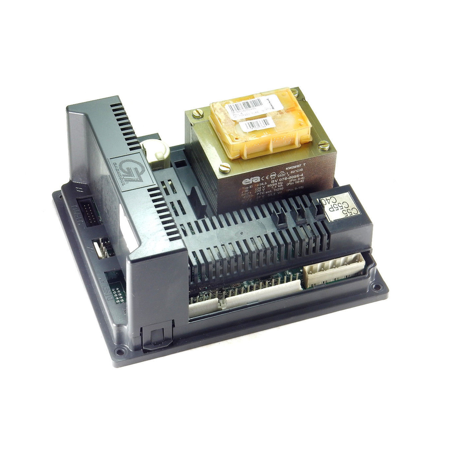
- Page 40 WD265/0/2002 Chapter 5 : Fault Finding The Keston C40, C40P, C55 & C55P 5.7.5 Exploded Diagrams Parts Reference List Boiler Controls Assembly (Fig. 5.7.1) GC Number Code Description E93-126 C55/C55P/C40 Main Control Box (C.17.4.01.00.0) E93-127 C40P Main Control Box (C.13.4.03.00.0) E93-130 Control Panel (C.17.4.02.00.0)
- Page 41 It should be noted that setting the user controls to “Standby” does not isolate the electrical supply and parts of the boiler will remain live. Hazardous materials are not used in the construction of the C40 and C55. However, due care should be taken when handling boiler components.
- Page 42 WD265/0/2002 Chapter 6 : Servicing The Keston C40, C40P, C55 & C55P Remove the condensate trap (Section 7.8) and clean by flushing through with clean running water. Check the electrode assembly mounted on the heat exchanger. If the point is damaged or burnt replace it.
-
Page 43: Replacement Of Parts
WD265/0/2002 Chapter 7 : Replacement Of Parts The Keston C40, C40P, C55 & C55P 7. REPLACEMENT OF PARTS CONTENTS GENERAL PRECAUTIONS ACCESS REPLACEMENT PROCEDURE ELECTRICAL COMPONENTS 7.4.1 CONTROL PANEL 7.4.2 BOILER FLOW & RETURN THERMISTORS 7.4.3 CABINET TEMPERATURE SENSOR 7.4.4 FLUE PROTECTION THERMOMSTAT 7.4.5... - Page 44 WD265/0/2002 Chapter 7 : Replacement Of Parts The Keston C40, C40P, C55 & C55P 7.4.2 Boiler Flow and Return Thermistors (Fig. 5.7.2 item 47) Isolate the appliance (Section 7.1) Gain access (Section 7.2) iii) Remove the push on connectors from the thermistor taking note of the correct positions.
- Page 45 WD265/0/2002 Chapter 7 : Replacement Of Parts The Keston C40, C40P, C55 & C55P 7.4.8 Gas Control Valve / Venturi Assembly (Fig. 5.7.3 item 163) Isolate the appliance (Section 7.1) Gain access (Section 7.2) iii) Remove the push on connector block to the gas valve.
- Page 46 WD265/0/2002 Chapter 7 : Replacement Of Parts The Keston C40, C40P, C55 & C55P Remove the two screws fixing the heat exchanger to the top mounting bracket (Fig 5.7.2 item 63) xii) Remove the heat exchanger xiii) Reassemble (Section 7.3)
- Page 47 WD265/0/2002 Chapter 8 : Spare Parts Listings The Keston C40, C40P, C55P & C55P 8. SHORT SPARE PARTS LIST Item GC No Part Denomination Item GC No PartDenomination E93-137 C55 Burner E93-141 Burner Gasket E93-138 C55P/C40/C40P Burner E93-142 Ignitor Gasket...
- Page 48 WD265/0/2002 Chapter 8 : Spare Parts Listings The Keston C40, C40P, C55 & C55P SHORT SPARE PARTS LIST FOR THE KESTON CONDENSING BOILER RANGE Item GC No Part Denomination E93-145 Flow/Return Temperature Thermistor 114-045 Water Pressure Switch E72-332 Flue Protection Thermostat...
- Page 49 WD209/1/2000 Chapter 9 : Benchmark Checklist Final The Keston Celsius 25 & 25P 9. GAS BOILER COMMISSIONING CHECKLIST BENCHMARK No. GAS BOILER COMMISSIONING CHECKLIST BOILER SERIAL No. ___________________ NOTIFICATION No. ____________________ CONTROLS To comply with the Building Regulation, each section must have a tick in one or other of the boxes TIME &...
-
Page 50: Service Interval Record
WD209/1/2000 Chapter 9 : Benchmark Checklist Final The Keston Celsius 25 & 25P SERVICE INTERVAL RECORD It is recommended that your heating system is serviced regularly and that you complete the appropriate Service Interval Record Below Service Provider. Before completing the appropriate Service Interval Record below, please ensure you have carried out the service as described in the boiler manufacturer’s instructions. - Page 51 KESTON CONDENSING BOILERS IMPORTANT C40 & C55 INSTALLATION KEY POINTS † Read Installation Manual Carefully † Ensure that there is at least 9 feet head of water pressure at the top of the boiler . † Ensure that ALL dust particles, filings , plastic chips etc. are removed from the inlet pipe.
- Page 52 LPG CONVERSION INSTRUCTIONS FOR KESTON C40 MODEL The Keston C40 condensing boiler are supplied fabricated for Natural Gas combustion at a supply pressure of 20 mbar. These conversion instructions must be read in conjunction with the Keston C40 Installation &...
- Page 53 If following the above procedure, combustion levels described above at both high and low rate could not be obtained, please turn off the appliance and isolate the gas to the appliance. Telephone KESTON BOILERS technical support (phone no. 0208 462 0262) To revert to normal modulation Press the “Mode”...
- Page 54 NG CONVERSION INSTRUCTIONS FOR KESTON C40P MODEL The Keston C40P condensing boiler are supplied fabricated for LP Gas combustion at a supply pressure of 37 mbar. These conversion instructions must be read in conjunction with the Keston C40P Installation &...
- Page 55 If following the above procedure, combustion levels described above at both high and low rate could not be obtained, please turn off the appliance and isolate the gas to the appliance. Telephone KESTON BOILERS technical support (phone no. 0208 462 0262) To revert to normal modulation Press the “Mode”...
- Page 56 LPG CONVERSION INSTRUCTIONS FOR KESTON C55 MODEL The Keston C55 condensing boiler are supplied fabricated for Natural Gas combustion at a supply pressure of 20 mbar. These conversion instructions must be read in conjunction with the Keston C55 Installation &...
- Page 57 If following the above procedure, combustion levels described above at both high and low rate could not be obtained, please turn off the appliance and isolate the gas to the appliance. Telephone KESTON BOILERS technical support (phone no. 0208 462 0262) To revert to normal modulation Press the “Mode”...
- Page 58 NG CONVERSION INSTRUCTIONS FOR KESTON C55P MODEL The Keston C55P condensing boiler are supplied fabricated for LP Gas combustion at a supply pressure of 37 mbar. These conversion instructions must be read in conjunction with the Keston C55P Installation &...
- Page 59 If following the above procedure, combustion levels described above at both high and low rate could not be obtained, please turn off the appliance and isolate the gas to the appliance. Telephone KESTON BOILERS technical support (phone no. 0208 462 0262) To revert to normal modulation Press the “Mode”...
- Page 60 Gas valve/Venturi assembly replacement procedure for KESTON C55, C40, C55P and C40P boilers. These conversion instructions must be read in conjunction with the Keston C55 & C40 Installation & Servicing Instructions – WD265. Before proceeding to the replacement procedure please check if the tamper paint on the offset adjustment cap (see attached picture) is intact.
- Page 61 If CO levels above these values are experienced, the combustion chamber and flue system should be investigated. The C55 & C40 are factory set for combustion and should need no adjustment. However, in the event adjustment is required. Check combustion errors are not a result of incorrectly installed flue and/or air system, terminal location or damage or debris on the burner.
Need help?
Do you have a question about the C40 and is the answer not in the manual?
Questions and answers