Table of Contents
Advertisement
Advertisement
Table of Contents

Subscribe to Our Youtube Channel
Related Manuals for Dettson R02P029


Summary of Contents for Dettson R02P029
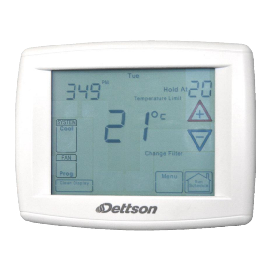
- Page 1 INSTALLATION AND OPERATING INSTRUCTIONS Communicating Touchscreen Thermostat Model R02P029 FAILURE TO READ AND FOLLOW ALL INSTRUCTIONS CAREFULLY BEFORE INSTALLING OR OPERATING THIS CONTROL COULD CAUSE PERSONAL INJURY AND/OR PROPERTY DAMAGE. 2015-09-22 X00482 Rev.A...
-
Page 2: Table Of Contents
TABLE OF CONTENT Introduction Thermostat 6.2.2- Dual Fuel System Disable .... 9 Communicating System ........4 6.2.3- Air Handler Lockout Temperature 9 Safety ............. 4 6.3- Permanent Temperature Hold ..9 Installation ..........4 6.4- Normal Mode ........9 3.1- Battery Location ......... - Page 3 LIST OF TABLES Tableau 1: Thermostat User Menus ....13 Tableau 20: Fault History Heat Pump User Menu Tableau 2: Status User Menu ......13 ................ 19 Tableau 3: Setup User Menu ......14 Tableau 21: 2 week History Heat Pump User Tableau 4: Status 1 Furnace User Menu ..
-
Page 4: 1- Introduction To Thermostat And
instructions of the furnace or air handler and 1- INTRODUCTION TO outdoor AC condensing unit or heat pump are THERMOSTAT AND provided with each of these devices. COMMUNICATING SYSTEM 3.1- BATTERY LOCATION The system consists of a premium indoor Figure 1: Battery Location furnace or air handler, an outdoor AC condensing unit or heat pump and touchscreen thermostat that is the HVAC command center. -
Page 5: Quick Install Steps
3.3- QUICK INSTALL STEPS 4.1- MESSAGE AT THERMOSTAT Determine location thermostat installation. Mount thermostat base to wall. Connect wires to thermostat base. Remove battery tag to provide battery power to the thermostat. Attach thermostat to base. Turn power system. Allow approximately 1 minute for the system to configure. -
Page 6: 2- Heating System
Press FAN until FAn Auto is displayed. The Touch either the key until you reach the fan should stop operating. correct hour and AM or PM designation. Then touch Set Time again to display minutes only in 4.3.2- Heating System clock display. -
Page 7: Choose The System Setting (Cool, Off, Heat, Em, Auto)
5.2- CHOOSE THE SYSTEM SETTING a menu option. Touch to advance to the next (COOL, OFF, HEAT, EM, AUTO) menu item or to return to the previous menu item. Touch Run Schedule at any time to exit the menu and return to Home Screen Display. Touch the SYSTEM key to select: Cool: Thermostat controls only the cooling Select continuous FAN speed. - Page 8 Select temperature offset. Scrolling message Select air filter maintenance reminder. Scrolling will show “TEMPERATURE ADJUSTMENT”. message will show “AIR FILTER Your thermostat was accurately calibrated at the MAINTENANCE”. Default is OFF. It can be factory, however this option allows you to change changed to a setting from 25 to 1975 hours in the display temperature to match your previous increments of 25 hours to select the amount of...
-
Page 9: 6- Using The Thermostat
6.2.2- Dual Fuel System Disable This feature is applicable only when a heatpump is connected on the communication network. When this feature is selected, the thermostat will switch to fossil fuel heat and shut off the compressor when the outside temperature falls below the DF balance point. -
Page 10: Auto Mode
6.5- AUTO MODE 6.8- MAINTENANCE REMINDER MESSAGE In Programmable mode or Non-programmable mode, you can touch the SYSTEM key to select A reminder will display in the scrolling message AUTO to allow the thermostat to automatically area when it is time for accessory maintenance if change between Heat and Cool. -
Page 11: Fault Status
To change the display to the Equipment User Menu, touch Touch and hold the Installer Config key to 7.3- EQUIPMENT USER MENUS approximately 3 seconds to enter the Thermostat Options Configuration Menu. The equipment found in the system will display in the scrolling message area. - Page 12 Touch to step through the items of the Touch Menu to step out of the equipment equipment submenu and view settings. submenu parameters back to the equipment submenu. Each touch of Menu will step up one If a setting can be adjusted, the keys will menu level back to the Thermostat Options appear.
-
Page 13: Thermostat User Menu
Each Equipment User Menu has submenus to divide the information into categories. Each equipment has a different set of submenus, with different parameters depending on the equipment. The submenus are showing similar information for each equipment. The submenus and the information they provide are: Tableau 1: User Menus Status Used to display or modify equipment settings... -
Page 14: Furnace User Menus
Tableau 3: Setup User Menu Setup Parameter Options Comments bL – (7 Days Programming only) Factory default is (bLink), alternates time display between time and outdoor temperature. Outdoor On – (0 Days Programming default) The outdoor Temperature bL, On, OFF Display temperature is displayed continuously on the time display. -
Page 15: Tableau 5: Status 2 Furnace User Menu
Tableau 5: Status 2 Furnace User Menu Status 2 Parameter Indications Comments Mod Heat, Lo Heat, Hi Heat, AC1, AC2, Fan Only, Off, Mode Indicates Operating Mode of System HP1, HP2 Motor Mfgr Regblt, Emerson Blower Motor Manufacturer Motor RPM Blower Motor RPM Maximum CFM CFM XXXX... -
Page 16: Tableau 9: Life History Furnace User Menu
Tableau 8: 2 week history Furnace User Menu 2 week History (2 wK HIST) Parameter Indications Comments 2wk Lo HT Hrs 2 Weeks Low Heat Hours of Operation 2wk Lo HT Cycls XXXX 2 Weeks Low Heat Cycles 2wk Hi HT Hrs 2 Weeks High Heat Hours of Operation 2wk Hi HT Cycls XXXX... -
Page 17: Air Handler User Menus
Tableau 11: Dipswitch Furnace User Menu Dipswitch* Dip Switch Indications Comments Cool Airflow XXXXCFM Airflow Dipswitch Settings Heat Rise Nom, Nom+10 Heat Rise Airflow Settings Hi Heat Adj -15%, -7%, 0%, 7%, 15% High Heat Airflow Settings Lo Heat Adj -15%, -7%, 0%, 7%, 15% Low Heat Airflow Settings Fan Spd Select... -
Page 18: Tableau 16: Unit Info Air Handler User Menu
Tableau 14: 2 week History Air Handler User Menu 2 week History (2 wK HIST) Parameter Indications Comments 2wk AuxHT Hrs 2 Week Auxiliary Heat Hours of Operation 2wk AuxHT Cycls XXXX 2 Week Auxiliary Heat Cycles 2wk G Hrs 2 Week Blower Hours of Operation 2wk G Cycles XXXX... -
Page 19: Heat Pump User Menus
7.7- HEAT PUMP USER MENUS “X” in the following tables indicate alpha or numeric character. Tableau 19: Status Het Pump User Menu Status Parameter Indications Comments Compressor Off, On Compressor Status AC, AC1, AC2, HP, HP1, HP2, Mode System Mode of Operation Defrost, Time Delay, Off Comp Hi Pres SW... -
Page 20: Air Conditioner User Menus
Tableau 23: Unit Info Heat Pump User Menu Unit Info Parameter Indications Comments Model Number XXXX-XXXXXXXXXXXXXXXX Unit Model Number Unit Serial Number (not available if Serial Number XXXXXXXXXXXXXXXXXXX control is replaced) Software Vers XXXXXX Control Software Version Tableau 24: Cool Setup Heat Pump User menu Cool Setup Parameter Options... -
Page 21: Tableau 30: Unit Info Air Conditioner User
Tableau 27: Fault History Air Conditioner User Menu Fault History (FAULT HIST) Fault Code Fault Occurred Comments Displays up to 6 faults; Days (XX) indicates how many days ago the fault XXXXXXXXXXXXXXX Days XX occurred Clear Faults No, Yes Tableau 28: 2 week History Air Conditioner user menu 2 week History (2 wK HIST) Parameter Indications... -
Page 22: Modulating Chinook Furnace Fault Codes
8- MODULATING CHINOOK FURNACE FAULT CODES Display code Diagnostic Description Long Run Time System Pressure Trip Short Cycling 4 (L4) Locked Rotor 5 (L5) Open Circuit 6 (L6) Open Start Circuit 7 (L7) Open Run Circuit Low Secondary Voltage Failed ignition Low flame sense current Flame lost after established Flame present with gas valve off...
Need help?
Do you have a question about the R02P029 and is the answer not in the manual?
Questions and answers