
Related Manuals for SEW MOVITRAC LTP-B


Summary of Contents for SEW MOVITRAC LTP-B
-
Page 1: Operating Instructions
*22872051_0916* Drive Technology \ Drive Automation \ System Integration \ Services Operating Instructions Standard Inverters ® MOVITRAC LTP-B Edition 09/2016 22872051/EN... - Page 2 SEW-EURODRIVE—Driving the world...
-
Page 3: Table Of Contents
Table of contents Table of contents General information........................ 8 About this documentation .................... 8 Structure of the safety notes ................... 8 1.2.1 Meaning of signal words ................ 8 1.2.2 Structure of section-related safety notes............ 8 1.2.3 Structure of embedded safety notes .............. 8 Rights to claim under limited warranty ................ 9 Content of the documentation.................. 9 Exclusion of liability...................... 9... - Page 4 Startup for asynchronous motors with VFC torque control ...... 61 5.3.4 Startup of synchronous motors without encoder feedback (PMVC control).. 62 5.3.5 Startup with LSPM motors from SEW‑EURODRIVE ........ 63 5.3.6 Startup with preset motors from SEW‑EURODRIVE ........ 64 Startup of control...................... 65 5.4.1 Terminal mode (factory setting) P1-12 = 0...........
- Page 5 Table of contents 5.5.3 Hoisting mode .................... 72 5.5.4 Troubleshooting and optimizing the hoist function ........ 73 Fire mode/emergency mode .................. 74 Operation at 87 Hz characteristic.................. 75 Motor potentiometer function – crane application ............ 75 5.8.1 Motor potentiometer operation .............. 76 5.8.2 Terminal assignment ..................
- Page 6 Table of CANopen-specific objects ............ 106 7.4.8 Table of manufacturer-specific objects ............ 108 7.4.9 Emergency code objects ................ 108 Service ........................... 109 Electronics Service by SEW‑EURODRIVE.............. 109 Extended storage...................... 109 Waste disposal...................... 110 Parameters .......................... 111 Overview of parameters.................... 111 9.1.1 Parameters for realtime monitoring (read only).......... 111 9.1.2...
- Page 7 Table of contents 11.1.1 Safe condition .................... 193 11.1.2 Safety concept ................... 193 11.1.3 Restrictions .................... 196 11.2 Safety conditions...................... 197 11.2.1 Storage requirements................. 197 11.2.2 Installation requirements ................ 197 11.2.3 Requirements on the external safety controller.......... 199 11.2.4 Requirements for safety relays .............. 200 11.2.5 Requirements on startup ................
-
Page 8: General Information
If you are unclear about any of the information in this documentation or require further in- formation, contact SEW‑EURODRIVE. Structure of the safety notes 1.2.1... -
Page 9: Rights To Claim Under Limited Warranty
Read the information in this documentation, otherwise safe operation is impossible. You must comply with the information contained in this documentation to achieve the specified product characteristics and performance features. SEW‑EURODRIVE as- sumes no liability for injury to persons or damage to equipment or property resulting... -
Page 10: Safety Notes
If you are unclear about any of the information in this documentation, or if you re- quire further information, contact SEW‑EURODRIVE. The operator must ensure that the following works are only performed by qualified per- sonnel: •... -
Page 11: Designated Use
Safety notes Designated use Specialist for elec- Any electronic work may only be performed by adequately skilled persons (electric- trotechnical work ally). Qualified electricians in the context of this documentation are persons familiar with electrical installation, startup, troubleshooting and servicing of the product who possess the following qualifications: •... -
Page 12: Functional Safety Technology
Safety notes Functional safety technology Functional safety technology The product must not perform any safety functions without a higher-level safety sys- tem, unless explicitly allowed by the documentation. Transport Inspect the shipment for damage as soon as you receive the delivery. Inform the ship- ping company immediately about any damage. -
Page 13: Restrictions Of Use
Safety notes Electrical connection 2.7.1 Restrictions of use The following applications are prohibited unless explicitly permitted: • Use in potentially explosive areas • Use in areas exposed to harmful oils, acids, gases, vapors, dust, and radiation • Operation in applications with impermissibly high mechanical vibration and shock loads in excess of the regulations stipulated in EN 61800-5-1 •... -
Page 14: Protective Separation
When in doubt, switch off the product whenever changes occur in relation to normal operation. Possible changes are e.g. increased temperatures, noise, or oscillation. De- termine the cause. Contact SEW‑EURODRIVE if necessary. When the device is switched on, dangerous voltages are present at all power connec- tions as well as at any connected cables and terminals. -
Page 15: Device Structure
Device structure Nameplate Device structure Nameplate The following figure shows an example of a nameplate. 18014412064772491 Type designation Example: MCLTP-B 0015-2B1-4-00 (60 Hz) ® Product name MCLTP MOVITRAC LTP-B Version Version status of the device series Recommended motor 0015 0015 = 1.5 kW power Connection voltage 2 = 200 –... -
Page 16: Device Structure Of The Standard Inverter
Device structure Device structure of the standard inverter Device structure of the standard inverter 3.3.1 Inverters with degree of protection IP20/NEMA 1 The following inverters have the housing shown below: Nominal line voltage Power of the inverter 230 V 0.75 – 5.5 kW 400 V 0.75 –... -
Page 17: Inverters With Degree Of Protection Ip66/Nema 4X
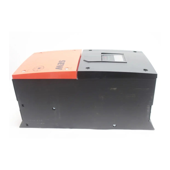
Device structure Device structure of the standard inverter 3.3.2 Inverters with degree of protection IP66/NEMA 4X The following inverters have the housing shown below: Nominal line voltage Power of the inverter 230 V 0.75 – 4 kW 400 V 0.75 – 7.5 kW 575 V 0.75 –... -
Page 18: Inverters With Degree Of Protection Ip55/Nema 12K
Device structure Device structure of the standard inverter 3.3.3 Inverters with degree of protection IP55/NEMA 12K The following inverters have the housing shown below: Nominal line voltage Power of the inverter 230 V 5.5 – 75 kW 400 V 11 – 160 kW 575 V 15 –... -
Page 19: Installation
Installation General information Installation General information • Carefully check the inverter for damage before the installation. • Store the inverter in its original packaging until it is used. The storage location must be clean and dry with an ambient temperature between ‑40 °C and +60 °C. •... -
Page 20: Permitted Tightening Torques
Installation Permitted tightening torques Permitted tightening torques Tightening torque in Nm for inverter Power of the inverter Control terminals Power terminals Nominal line voltage 230 V 0.75 – 2.2 kW 3 – 5.5 kW (IP20) 1 (IP20) 3 – 4 kW (IP66) 1 (IP66) 5.5 kW (IP66) 4 (IP66) 7.5 –... -
Page 21: Mechanical Installation
Installation Mechanical installation Mechanical installation 4.3.1 IP20 housing: Installation and installation space Inverters with degree of protection IP20 must be installed in a control cabinet. Observe the following requirements: • The control cabinet must be made of a heat conductive material unless it has forced cooling. -
Page 22: Ip55/Ip66 Housing: Installation And Control Cabinet Dimensions
Installation Mechanical installation 4.3.2 IP55/IP66 housing: Installation and control cabinet dimensions Inverters with degree of protection IP55/IP66 can be used indoors. In control cabinets or in field, the following minimum distances must not be underrun. 9007208910888971 Power of the inverter A in mm B in mm 230 V... -
Page 23: Electrical Installation
Installation Electrical installation Electrical installation WARNING Electric shock due to charged capacitors. Dangerous voltage levels may still be present inside the device and at the terminals up to 10 minutes after disconnection from the power supply. Severe or fatal injuries. • Wait 10 minutes after you have de-energized the inverter and have switched off the line voltage and the DC 24 V voltage. -
Page 24: Line Contactors
Installation Electrical installation • Do not loop the ground connections of the inverter from one inverter to the other. Neither route the ground connections to the inverters from other inverters. • The impedance of the ground circuit must comply with the local safety regulations of the industry sector. -
Page 25: Mains Fuses
• If the use of a residual current device is not mandatory according to the standards, SEW‑EURODRIVE recommends not to use a residual current device. ® Operating Instructions – MOVITRAC... -
Page 26: Operation On An It System
Protection Earth 9007204745593611 SEW‑EURODRIVE recommends using earth-leakage monitors with pulse code meas- urement in voltage supply systems with a non-grounded star point (IT systems). Use of such devices prevents the insulation monitor mis-tripping due to the earth capacit- ance of the inverter. -
Page 27: Operation On A Tn System With An Rcd Switch (Ip20)
Installation Electrical installation 4.4.5 Operation on a TN system with an RCD switch (IP20) ® IP20 inverters with integrated EMC filter (such as MOVITRAC LT xxxx xAx-x-00 or ® MOVITRAC LT xxxx xBx-x-00) have a higher leakage current than devices without EMC filter. -
Page 28: Removing The Terminal Cover
Installation Electrical installation 4.4.8 Removing the terminal cover To access the terminals of inverters with degree of protection IP55/IP66, remove the front cover of the frequency inverter. Only use cross-head or slot screwdrivers to open the terminal cover. The connection terminals can be accessed when the screws on the front of the product are removed as shown below. - Page 29 Installation Electrical installation Inverters with degree of protection IP55/NEMA 12K The following inverters have the housing shown below: Nominal line voltage Power of the inverter 230 V 5.5 – 75 kW 400 V 11 – 160 kW 575 V 15 – 110 kW 9007212609488907 • 230 V: 5.5 –...
-
Page 30: Cable Gland Plate
Installation Electrical installation 4.4.9 Cable gland plate A suitable cable gland system is required to maintain the respective IP/NEMA degree of protection. Cable entry holes have to be drilled that correspond to this system. NOTICE Drilling cable entry holes may lead to particles entering the inverter. Possible damage to property. -
Page 31: Connecting And Installing The Braking Resistor
Installation Electrical installation 4.4.10 Connecting and installing the braking resistor WARNING Danger of electric shock. The supply cables to the braking resistors carry a high voltage (approx. DC 900 V) during rated operation. Severe or fatal injuries. • Before removing the supply cable, disconnect the inverter from the power supply and wait at least 10 minutes. -
Page 32: Motor Temperature Protection Tf, Th, Kty84, Pt1000
Installation Electrical installation 4.4.11 Motor temperature protection TF, TH, KTY84, PT1000 Motors with internal temperature sensor (TF, TH, KTY84, PT1000 or similar) can be directly connected to the inverter. If the thermal protection is triggered, the inverter displays the error "F-PTC". For motor protection monitoring, the following types can be selected: •... -
Page 33: Multi-Motor Drive/Group Drive
For detailed information about the SEW‑EURODRIVE brake system, refer to the "AC Motors" catalog, which you can order from SEW‑EURODRIVE. SEW‑EURODRIVE brake systems are disk brakes with a DC coil that release electric- ally and brake using spring force. A brake rectifier supplies the brake with DC voltage. -
Page 34: Ul-Compliant Installation
Installation Electrical installation 4.4.15 UL-compliant installation Note the following information for UL-compliant installation: Ambient temperatures The inverters can be operated at the following ambient temperatures: Degree of protection Ambient temperature IP20/NEMA 1 -10 °C to 50 °C IP55/NEMA 12K -10 °C to 40 °C IP66/NEMA 4X Use only copper connection cables suited for ambient temperatures up to 75 °C. - Page 35 Installation Electrical installation 3 × 200 – 240 V devices 3 × 200 − 240 V Fuse or MCB (type B) Max. supply short circuit Max. line voltage current 0008 10 A 100 kA rms (AC) 240 V 0015 15 A 0022 17.5 A 0030 30 A 0040 30 A 0055 40 A...
- Page 36 Installation Electrical installation 3 × 500 – 600 V devices 3 × 500 − 600 V Fuse or MCB (type B) Max. supply short circuit Max. line voltage current 0008 6 A 100 kA rms (AC) 600V 0015 6 A 0022 10 A 0040 10 A 0055 15 A 0075 20 A...
-
Page 37: Information Regarding Ul
Installation Electrical installation 4.4.16 Information regarding UL INFORMATION Due to UL requirements, the following chapters are always printed in English inde- pendent of the language of the revision: Thermal motor protection Thermal motor overload protection shall be provided by one of the following means: •... -
Page 38: Electromagnetic Compatibility (Emc)
Installation Electrical installation 4.4.17 Electromagnetic compatibility (EMC) Inverters with EMC filters are designed for use in machines and drive systems. They meet the EMC product standard EN 61800-3 for drives with variable speed. Observe the specifications of Directive 2014/30/EU for EMC‑compliant installation of the drive system. - Page 39 Installation Electrical installation General information about connecting the motor shield We strongly recommend that you use the shield plate with LTX applications. Connect the shield by the shortest possible route and make sure it is earthed over a wide area at both ends. This also applies to cables with several shielded core strands. 9007200661451659 Recommendation for motor shield connection at frequency inverters with IP20 Inverters with de-...
- Page 40 Installation Electrical installation Example LTP-B inverter Example LTP-B inverter with LTX module 9007212157809419 [1] Motor cable [5] Control cables [2] Additional PE connection [6] • 230 V: 0.75 – 2.2 kW • 400 V: 0.75 – 4 kW • 575 V: 0.75 – 5.5 kW [3] Encoder cable [7] •...
- Page 41 Installation Electrical installation Recommendation for motor shield connection at frequency inverters with IP55/IP66 The use of metal screw fittings is recommended to connect the motor shield to the device. For the inverters listed below, the threads must be at least 8 mm. Inverters with de- The following inverters have the housing shown below: gree of protection...
- Page 42 Installation Electrical installation LTP-B LTP-B + LTX 9007212157811595 [1] Metal counter nut [4] LTX module [2] Metal cable gland [5] Motor cable [3] Enclosed rubber gasket [6] Supply system cable ® Operating Instructions – MOVITRAC LTP-B...
- Page 43 Installation Electrical installation Recommendation for routing the encoder, control and communication cables 9007212386365579 [1] Encoder cable, if LTX module [4] Signal terminal/communication [2] Signal terminal/communication [5] Supply system cable [3] Motor cable Inverters with de- The following inverters have the housing shown below: gree of protection Nominal line voltage Power of the inverter...
-
Page 44: Overview Of Signal Terminals
Installation Electrical installation The following inverters have the housing shown below: Nominal line voltage Power of the inverter 230 V 22 – 75 kW 400 V 45 – 160 kW 575 V 55 – 110 kW 18243537675 [1] Supply system cable [2] Metal cable gland [3] Motor cable 4.4.18 Overview of signal terminals... - Page 45 Installation Electrical installation The signal terminal block is equipped with the following connections: Ter- Signal Connection Description minal +24 VIO +24 V: Reference voltage/ Reference voltage for controlling the digital inputs backup voltage (max. 100 mA) Adhere to the "Note for connecting the STO function" (→ 2 46).
- Page 46 Installation Electrical installation All digital inputs are enabled with an input voltage in the range of 8 – 30 V. This means they are +24 V compatible. The response time of the digital and analog inputs is less than 4 ms. The resolution of the analog inputs is 12 Bit at an accuracy of ±2% in reference to the set maximum scaling.
-
Page 47: Communication Socket Rj45
Installation Electrical installation Relay terminals NOTICE Possible damage to property Do not connect any inductive loads to the relay contact. Ter- Signal Relay function selec- Description minal tion Relay output 1 reference P2-15 Relay contact (AC 250 V / DC 30 V, max. -
Page 48: Backup Mode
Installation Electrical installation 4.4.20 24 V backup mode The inverter allows for realizing a backup mode via external 24 V. This means the control electronics and the option cards such as the fieldbus cards are fully functional even when the power supply is switched off. Requirements Firmware version 1.20 (can be seen in P0-28). -
Page 49: Dc Link Connection
The DC link is routed on terminals for all power ratings. It is thus possible to couple all devices with a DC link connection or to directly supply them with DC voltage. Contact SEW‑EURODRIVE in such a case. Wiring diagram WARNING Danger of electric shock. - Page 50 Installation Wiring diagram L2/N not single-phase 230 V F11/F12/F13 (AC-3) Option ND.. input choke L1 ' L 2' L3 ' DC bus “–” access Power section B W .. / BW..-T braking resistor connection* DC bus “+” access 3-phase 18380767883 Line contactor between supply system and inverter.
-
Page 51: Brake Control
Installation Wiring diagram 4.5.1 Brake control V DC (BMV) V AC V AC (BMK) V AC F14/F15 F14/F15 F14/F15 (A C-3) (A C-3) C-3) (A C-3) (AC-3) white white BM K BG E BG E blue BM V white DR/DT/DV: DR/DT/DV: blue Cut-off in the DC... -
Page 52: Startup
Startup User interface Startup User interface 5.1.1 Keypads The inverters in IP20 design are equipped with a standard keypad. The inverters in IP55/IP66 design are equipped with a full text display with language switching function. Both keypads allow for operation and setup of the inverter without additional devices. Standard keypad 9007202188405387 [1] 6-digit 7-segment display... - Page 53 Startup User interface Operation Both keypads have 5 keys with the following functions: Start [2] • Enable drive • Changing the direction of rotation Stop [3] • Stop drive • Acknowledge error Navigate [4] • Switch menu • Save parameter values •...
-
Page 54: Resetting Parameters To Default Settings
Startup User interface 5.1.2 Resetting parameters to default settings To reset the parameters to the factory setting, proceed as follows: 1. The inverter must not be enabled and the display must show "Inhibit". 2. Press the 3 keys , and simultaneously for at least 2 s. -
Page 55: Software Lt Shell
Software LT Shell The LT Shell software enables an easy and quick startup of the inverters. It is avail- able for download on the SEW‑EURODRIVE website. After the installation, perform software updates on a regular basis. In combination with the engineering package (cable set C) and the USB11A interface adapter, the inverter can be connected to the software. - Page 56 Startup User interface ® Bluetooth LTP-B L1/L L2/N L3 1 2 3 4 5 6 7 8 9 10 11 12 13 14 15 16 17 18 9007216440559755 Parameter module ® Operating Instructions – MOVITRAC LTP-B...
-
Page 57: Movitools ® Motionstudio Engineering Software
• Save parameter settings • Monitor the state of the inputs/outputs and the motor. ® Connection to MOVITOOLS MotionStudio The connection can be set up indirectly via SEW‑EURODRIVE gateway or SEW‑EURODRIVE controller. Gateway LTP-B L1/L L2/N L3 DFP 21B FAULT... - Page 58 Startup User interface Controller LTP-B L1/L L2/N L3 DHP 11B 1 2 3 4 5 6 7 8 9 10 11 12 13 14 15 16 17 18 17186293003 Cable USB A-B Terminating connector (120 Ω) USB11A Cable splitter RJ10 to RJ10 cable Cable USB A-B RJ45 cable with open end RJ45 Ethernet cable...
-
Page 59: Automatic Measuring Procedure "Auto Tune
Startup Auto tune Auto tune Automatic measuring procedure "Auto tune" With the automatic measuring procedure, the inverter can measure almost any motor to determine the motor data. • After a reset to the factory settings, the measuring procedure starts automatically after the first enable and takes up to 2 minutes depending on the control type. -
Page 60: Startup For Asynchronous Motors With V/F Control
Startup Startup for motors 5.3.1 Startup for asynchronous motors with V/f control 1. Connect the motor to the inverter. During the connection, adhere to the nominal motor voltage. 2. Enter the motor data indicated on the motor nameplate: • P1-07 = nominal voltage of the motor •... -
Page 61: Startup For Asynchronous Motors With Vfc Torque Control
Startup Startup for motors 5.3.3 Startup for asynchronous motors with VFC torque control 1. Connect the motor to the inverter. During the connection, adhere to the nominal motor voltage. 2. Enter the motor data indicated on the motor nameplate: • P1-07 = nominal voltage of the motor •... -
Page 62: Startup Of Synchronous Motors Without Encoder Feedback (Pmvc Control)
Startup Startup for motors 5.3.4 Startup of synchronous motors without encoder feedback (PMVC control) The synchronous motors are permanent magnet motors. INFORMATION The operation of synchronous motors without encoder must be checked in a test ap- plication. Stable operation in this operating mode cannot be ensured for all applica- tion cases. -
Page 63: Startup With Lspm Motors From Sew-Eurodrive
Startup Startup for motors 5.3.5 Startup with LSPM motors from SEW‑EURODRIVE DR..J type motors are motors with LSPM technology (Line Start Permanent Magnet motors). 1. Connect the motor to the inverter. During the connection, adhere to the nominal motor voltage. -
Page 64: Startup With Preset Motors From Sew-Eurodrive
Startup Startup for motors 5.3.6 Startup with preset motors from SEW‑EURODRIVE Startup can be performed if one of the following CMP.. motors (speed class 4500 1/ min) or MGF..-DSM motors (speed class 2000 1/min) are connected to the inverter: Motor type Display... -
Page 65: Startup Of Control
Startup Startup of control Startup of control WARNING Installing sensors or switches at the terminals may cause an enable signal. The mo- tor may start up automatically. Severe or fatal injuries. • Make sure that no persons are within the reach of moving parts of the system. •... -
Page 66: Keypad Mode (P1-12 = 1 Or 2)
Startup Startup of control 5.4.2 Keypad mode (P1-12 = 1 or 2) For operation in keypad mode: • Set P1-12 to "1" (uni-directional) or "2" (bi-directional). • Connect a jumper or switch between terminals 1 and 2 on the terminal block to en- able the inverter. - Page 67 Startup Startup of control General informa- Connect the sensor for the controlled variable to analog input 1 or 2 depending on tion on the use P3-10. You can scale the sensor value using parameter P3-12 in such a way that the value is indicated on the inverter display with the proper quantity, for example 0 ...
-
Page 68: Master-Slave Mode (P1-12 = 4)
Startup Startup of control 5.4.4 Master-slave mode (P1-12 = 4) Master Slave 1 Slave 2 L1/L L2/N L3 L1/L L2/N L3 L1/L L2/N L3 1 2 3 4 5 6 7 8 9 10 11 12 13 1 2 3 4 5 6 7 8 9 10 11 12 13 1 2 3 4 5 6 7 8 9 10 11 12 13 IOIOI IOIOI... -
Page 69: Fieldbus Mode (P1-12 = 5, 6 Or 7)
Startup Startup of control Configuring the slave inverters • Each connected slave must have a unique slave communication address that is set with the inverter address P5-01. You can assign slave addresses from 2 to 63. Set: • P1-12 = 4 (control signal source) •... -
Page 70: Hoist Function
• Use a sufficiently dimensioned braking resistor. • SEW‑EURODRIVE recommends not to run the motor in very low speed ranges or to keep the load at zero speed without application of the brake. • If you need sufficient torque, operate the motor within its nominal range. -
Page 71: General Information
Startup Hoist function 5.5.1 General information • Clockwise rotating field of the motor corresponds to upward direction. • Counterclockwise rotating field of the motor corresponds to downward direction. • Stop the motor to reverse the direction of rotation. To do so, activate the brake. Set the controller inhibit before you reverse the direction of rotation. -
Page 72: Hoisting Mode
Startup Hoist function 5.5.3 Hoisting mode The following diagram shows hoisting mode. Setpoint speed Brake release speed P2-07 Brake application speed P2-08 Enable (DI01) Mechanical brake Contact relay 2 18014401720170891 Inverter enable The motor runs up to brake release speed (fixed setpoint speed 7). -
Page 73: Troubleshooting And Optimizing The Hoist Function
Startup Hoist function 5.5.4 Troubleshooting and optimizing the hoist function SP-Err / ENC02: Increase the speed error window in P6-07 if this error message appears. In case of problems such as sagging of the hoist, check the following parameters and/ or adapt: P1-03/04 = Reduce ramp times, pass through slow speed ranges as quickly as... -
Page 74: Fire Mode/Emergency Mode
Startup Fire mode/emergency mode Fire mode/emergency mode Set the fire mode/emergency mode as follows: • Perform a motor startup. • Set parameter P1-14 to "201" to access further parameters. • Set parameter P1-15 to "0" to configure the digital inputs. •... -
Page 75: Operation At 87 Hz Characteristic
Startup Operation at 87 Hz characteristic Operation at 87 Hz characteristic The V/f ratio remains the same at 87 Hz operation. However, higher power and speeds are generated which causes a higher current flow. 400 V 230 V 87 Hz 50 Hz 9007206616827403 Do the following to set "87 Hz characteristic"... -
Page 76: Motor Potentiometer Operation
Startup Motor potentiometer function – crane application 5.8.1 Motor potentiometer operation The following figure shows the basic function of the motor potentiometer. The descrip- tion in chapter "Parameter settings" (→ 2 77) is based on the frequently used crane function and works according to the terminal assignment in chapter "Terminal assignment" (→ 2 77). -
Page 77: Terminal Assignment
Startup Motor potentiometer function – crane application 5.8.2 Terminal assignment [1] [2] [3] 7834026891 [1] DI1 Reduce enable/speed [2] DI2 Increase speed [3] DI3 Fixed setpoint speed 1 [4] DI4 Change of direction (clockwise rotation/counterclockwise rotation) 5.8.3 Parameter settings Start up the motor as described in chapter "Startup" (→ 2 59). Make the following settings to being able to use the motor potentiometer: •... -
Page 78: Examples Of Analog Input Scaling And Offset Setting
Startup Examples of analog input scaling and offset setting Examples of analog input scaling and offset setting Analog input format, scaling and offset are connected to each other. Inverter setting: P1-01 = 50 Hz 5.9.1 Example 1: Analog input scaling Control 0 – 40 Hz with analog input 0 – 10 V: = 0 Hz, n = 40 Hz P2-31 = 80%... -
Page 79: Example 2: Analog Input Offset
Startup Examples of analog input scaling and offset setting 5.9.2 Example 2: Analog input offset Control 15 – 35 Hz with analog input 0 – 10 V: = 15 Hz, n = 35 Hz Offset P2-31 = 40%, P2-32 = -75% Analog input 13627144971 n - n −... -
Page 80: Example 3: Analog Input Scaling And Offset
Startup Examples of analog input scaling and offset setting 5.9.3 Example 3: Analog input scaling and offset Control 15 - 45 Hz with analog input 3 - 8 V: P2-31 = 120%, P2-32 = 5% Analog input 18364553227 18364558219 18364573451 ® Operating Instructions – MOVITRAC LTP-B... -
Page 81: Fans And Pumps
Startup Fans and pumps 5.10 Fans and pumps The following functions are available for applications with pumps or fans: • Voltage increase/boost (P1-11) • Adjustment of the V/f characteristic curve (P4-10, P4-11) • Energy-saving function (P1-06) • Flying start function (P2-26) •... -
Page 82: 3-Wire Control
Startup 3-wire control 5.12 3-wire control The function is activated via the digital input function selection P1-15 = 21. The 3-wire control principle determines the control. The enable and direction of rotation signals of the inverter then react edge controlled. •... -
Page 83: Operation
Operation Inverter status Operation The following information is displayed to being able to read off the operating state of the inverter at any time: Status Abbreviation display Drive OK Static inverter status Drive running Operating state of the inverter Fault / trip Fault Inverter status 6.1.1... -
Page 84: Operating State Of The Inverter
Operation Inverter status 6.1.2 Operating state of the inverter The list below shows the abbreviations that are displayed to indicate the inverter status when the motor is running. Pressing the "Navigate" key on the keypad lets you toggle between output frequency, output current, output power and speed. -
Page 85: Status Displays Of The Parameter Module
Operation Inverter status 6.1.3 Status displays of the parameter module The parameter module status is displayed on the frequency inverter display. Display Description PASS-r The parameter module successful read/saved the frequency inverter parameters. OS-Loc The parameter module is locked. Attempt to read parameter from frequency inverter with activated parameter module lock. -
Page 86: Troubleshooting
Operation Troubleshooting Troubleshooting Symptom Cause and solution Overload or overcurrent error of the Check the star/delta terminal connection in the motor. The nominal unloaded motor during acceleration operating voltage of motor and inverter must match. Delta connec- tion always yields the lower voltage of a multi-voltage motor. Overload or overcurrent –... -
Page 87: Error Codes
• the motor is connected correctly and without error. • the power rating of the motor corresponds with the power rating of the connected inverter. dAtA-E 0x62 0x1013 Internal memory Contact the SEW‑EURODRIVE Service. error (DSP) dAtA-F 0x62 0x1011 Internal memory Contact the SEW‑EURODRIVE Service. - Page 88 The connected motor protection sensor is defined in P2-33 triggered (PTC, TF, TH, KTY or PT1000), and connected to the analog input 2 (terminal 10). FAN-F 0x32 0x1016 Internal fan error. Contact the SEW‑EURODRIVE Service. FLt-dc 0x07 0x320D DC link ripple too Check the current supply. high.
- Page 89 Operation Error codes Error message Error code CANopen Explanation Solution Inverter display P0-13 status word if Emer- error history Bit5 = 1 gency Code Inverter MotionStu display dio cod- ing dec I.t-trp 0x08 0x1004 Overload of in- Make sure that: verter/motor •...
- Page 90 Note the minimum res- istor values for the used inverter. OF-01 0x1C 0x103C Internal connec- Contact the SEW‑EURODRIVE Service. tion to option module error. OF-02 0x1C 0x103D Option module Contact the SEW‑EURODRIVE Service.
- Page 91 Bit5 = 1 gency Code Inverter MotionStu display dio cod- ing dec SC-F05 0x29 0x1036 LTX module com- Contact the SEW‑EURODRIVE Service. munication error SC-F01 0x2B 0x1032 Modbus commu- Check the communication settings. nication error SC-F02 0x2F 0x1033 SBus/CANopen Check: communication •...
-
Page 92: Fieldbus Mode
Fieldbus mode General information Fieldbus mode General information 7.1.1 Structure and settings of process data words Control and status word have a fixed assignment. All the other process data words can be freely configured as required using parameter group P5-xx. The structure of process data words is identical for SBus/Modbus RTU/CANopen, as well as with inserted communication card. - Page 93 Fieldbus mode General information Process input words Description Settings Byte Status word 0 Output stage enable 0: Disabled Low byte 1: Enabled Frequency inverter ready 0: Not ready for operation 1: Ready PO data enabled 1 if P1-12 = 5 3 – 4 Reserved Fault/warning...
-
Page 94: Communication Example
Fieldbus mode General information 7.1.2 Communication example The following information is sent to the inverter if • The digital inputs have been configured and wired properly to enable the inverter. Description Value Description Control word 0x0000 Stop along the second Deceleration ramp (P2-25). 0x0001 Coast to a stop 0x0002... -
Page 95: Connecting The Signal Terminals At The Inverter
Fieldbus mode General information 7.1.4 Connecting the signal terminals at the inverter For bus mode, you can connect the signal terminals using the default setting of P1-15 as described in chapter "Overview of signal terminals" (→ 2 44). When the DI3 signal level changes, the system toggles between the speed setpoint source fieldbus (low) and fixed setpoint 1 (high). -
Page 96: Connecting A Gateway Or Controller (Sbus Movilink ® )
MOVILINK profile CAN/SBus application profile from SEW‑EURODRIVE specifically adjusted to SEW inverters. For detailed information, ® refer to the "MOVIDRIVE MDX60B/61B Communication and Fieldbus Device Profile" manual. For using SBus, configure the inverter as described in chapter "Parameter settings for the inverter" (→ 2 94). -
Page 97: Startup At Gateway
Fieldbus mode Connecting a gateway or a controller (SBus MOVILINK) Wiring from the control to the "communication socket RJ45" (→ 2 47) of the inverter: Side view Designation Terminal at CCU/PLC Signal RJ45 socket Signal ® MOVI-PLC or Gate- X26:1 CAN 1H SBus/CAN bus h way (DFX/UOH) X26:2 CAN 1L... -
Page 98: Startup At A Ccu
Fieldbus mode Connecting a gateway or a controller (SBus MOVILINK) 7.2.4 Startup at a CCU Before taking the inverter into operation with "Drive Startup" in MotionStudio, you have to set the following parameters directly on the inverter: • Set parameter P1-14 to "1"... -
Page 99: Modbus Rtu
Fieldbus mode Modbus RTU Modbus RTU The inverters support communication via Modbus RTU. Holding registers (03) are used for reading, and single holding registers (06) for writing. For using Modbus RTU, configure the inverter as described in chapter "Parameter settings for the inverter" (→ 2 94). -
Page 100: Register Allocation Of The Process Data Words
Fieldbus mode Modbus RTU 7.3.3 Register allocation of the process data words The process data words are allocated to the Modbus registers shown in the table. The status and control words have a fixed allocation. The other process data words can be configured as required in parameter group P5-xx. -
Page 101: Data Flow Example
Fieldbus mode Modbus RTU 7.3.4 Data flow example In this example, the following parameters are read by the controller (PLC address base = 1): • P1-07 (rated motor voltage, modbus register 107) • P1-08 (rated motor current, modbus register 108). Request master → slave (Tx) Reading register Address... - Page 102 Fieldbus mode Modbus RTU Start address Register start address =0x0001 = 1 (first register to be written on = 2 PA2) Information 0700 (setpoint speed) 2 × CRC bytes CRC_high, CRC_low ® Operating Instructions – MOVITRAC LTP-B...
-
Page 103: Canopen
Fieldbus mode CANopen CANopen The inverters support communication via CANopen. For using CANopen, configure the inverter as described in chapter "Parameter settings for the inverter" (→ 2 94). Following a general overview of how to establish a communication connection via CANopen and the process data communication. The CANopen configuration is not de- scribed. -
Page 104: Supported Transmission Modes
Fieldbus mode CANopen 7.4.4 Supported transmission modes The various transmission types can be selected for every process data project (PDO) in the network management (NMT). The following transmission types are supported for Rx-PDOs: Rx PDO transmission mode Transmission Mode Description type 0 –... -
Page 105: Data Flow Example
Fieldbus mode CANopen 7.4.6 Data flow example Process data communication example with default setting: Word 1 Word 2 Word 3 Word 4 COB ID DB Byte 1 Byte 2 Byte 3 Byte 4 Byte 5 Byte 6 Byte 5 Byte 6 Description 0x701 "00"... -
Page 106: Table Of Canopen-Specific Objects
Fieldbus mode CANopen 7.4.7 Table of CANopen-specific objects CANopen-specific objects Index Sub in- Function Access Type PDO map Default value 1000h Device type Unsigned 32 1001h Error register Unsigned 8 1002h Manufacturer status register Unsigned 16 1005h COB-ID Sync Unsigned 32 00000080h 1008h Manufacturer device name... - Page 107 Fieldbus mode CANopen CANopen-specific objects Index Sub in- Function Access Type PDO map Default value 1A01h Tx PDO2 mapping / no. of entries Unsigned 8 Tx PDO2 1st mapped object Unsigned 32 21180010h Tx PDO2 2nd mapped object Unsigned 32 21190010h Tx PDO2 3rd mapped object Unsigned 32...
-
Page 108: Table Of Manufacturer-Specific Objects
Fieldbus mode CANopen 7.4.8 Table of manufacturer-specific objects The manufacturer-specific objects of the inverter are defined as follows: Manufacturer-specific objects Index Sub in- Function Access Type Note 2000h Reserved / no function Unsigned 16 Read as 0, writing not possible 2001h Integer 16 Defined as command... -
Page 109: Service
Service Electronics Service by SEW‑EURODRIVE Service To ensure fault-free operation, SEW-EURODRIVE recommends that you check the ventilation openings in the housing at regular intervals and clean them if necessary. Electronics Service by SEW‑EURODRIVE If you are unable to rectify a fault, contact SEW‑EURODRIVE... -
Page 110: Waste Disposal
Service Waste disposal • Step 3: AC 420 V for 15 minutes • Step 3: AC 500 V for 15 minutes • Step 4: AC 600 V for 1 hour After you have completed the regeneration process, the device can be used immedi- ately or stored again for an extended period with maintenance. -
Page 111: Parameters
Parameters for realtime monitoring (read only) Parameter group 0 gives access to internal inverter parameters for monitoring pur- poses. These parameters cannot be changed. Parameter group 0 is visible if P1-14 is set to "101" or "201". Para- SEW in- Modbus Description Display range Explanation... - Page 112 Parameters Overview of parameters Para- SEW in- Modbus Description Display range Explanation meters register P0-27 11294, MWh counter 0.0 – 65535 MWh 100 = 10.0 MWh (cumulative energy consumption) 11295 MWh counter (can be reset) P0-28 11247 – Software version and e.g. "1 1.00", "1 4F3C"...
- Page 113 Parameters Overview of parameters Para- SEW in- Modbus Description Display range Explanation meters register P0-49 11224 Counter for Modbus com- 0 – 65535 – munication errors P0-50 11225 Counter for CAN bus com- 0 – 65535 – munication errors P0-51 11256 –...
- Page 114 Parameters Overview of parameters Para- SEW in- Modbus Description Display range Explanation meters register P0-68 11229 User ramp value The indicating accuracy on the inverter display de- pends on the ramp time received via the fieldbus. For the inverters: • 230 V: 0.75 – 5.5 kW •...
- Page 115 Parameters Overview of parameters Para- SEW in- Modbus Description Display range Explanation meters register P0-79 11355, IO version and DSP boot- Example: L 1.00 2 entries; first for lib version of the motor control, 11356 loader version for motor Example: b 1.00 second for DSP bootloader version.
-
Page 116: Parameter Register
Parameters Overview of parameters 9.1.2 Parameter register The following table lists all parameters together with their factory settings (in- dicated in bold). Numerical values are displayed with the complete setting range. Modbus SBus/ Associated parameter Range/factory setting register CANopen index 11020 "P1-01 Maximum speed" (→ 2 122) P1-02 –... - Page 117 Parameters Overview of parameters Modbus SBus/ Associated parameter Range/factory setting register CANopen index 11039 "P2-04 Fixed setpoint speed 4" (→ 2 132) -P1-01 – 50.0 Hz – P1-01 11040 "P2-05 Fixed setpoint speed 5" (→ 2 132) -P1-01 – 0.0 Hz – P1-01 11041 "P2-06 Fixed setpoint speed 6" (→ 2 133) -P1-01 –...
- Page 118 Parameters Overview of parameters Modbus SBus/ Associated parameter Range/factory setting register CANopen index 11073 "P2-39 Parameter lock" (→ 2 142) 0: Disabled 11074 "P2-40 Extended parameter access code 0 – 101 – 9999 definition" (→ 2 142) 11075 "P3-01 PID proportional gain" (→ 2 142) 0 – 1 – 30 11076 "P3-02 PID integral time constant" (→ 2 142) 0 –...
- Page 119 Parameters Overview of parameters Modbus SBus/ Associated parameter Range/factory setting register CANopen index 11111 "P5-07 Ramp specified via fieldbus" (→ 2 152) 0: Disabled 11112 "P5-08 Synchronization duration" (→ 2 152) 0, 5 – 20 ms 11369 "P5-09 Fieldbus PO2 definition" (→ 2 153) 0 − 7 11370 "P5-10 Fieldbus PO3 definition" (→ 2 153) 0 −...
- Page 120 Parameters Overview of parameters Modbus SBus/ Associated parameter Range/factory setting register CANopen index 11143 "P7-04 Motor magnetization current (Id 10% × P1-08 − 80% × P1-08 rms)" (→ 2 162) 11144 "P7-05 Motor leakage loss coefficient 0,025 – 0.10 – 0.25 (sigma)" (→ 2 162) 11145 "P7-06 Motor stator inductance (Lsq) −...
- Page 121 Parameters Overview of parameters Modbus SBus/ Associated parameter Range/factory setting register CANopen index 11189 "P9-19 Input speed selection 1" (→ 2 170) OFF, din-1 – din-8, On 11190 "P9-20 Input speed selection 2" (→ 2 170) OFF, din-1 – din-8, On 11191 "P9-21 Fixed setpoint speed selection input OFF, din-1 –...
-
Page 122: Explanation Of The Parameters
Parameters Explanation of the parameters Explanation of the parameters 9.2.1 Parameter group 1: Basic parameters (level 1) P1-01 Maximum speed Setting range: P1-02 – 50.0 Hz – 5 × P1-09 (max. 500 Hz) Specifies the upper limit for the frequency (speed) that can be applied to the motor in any operating mode. - Page 123 Parameters Explanation of the parameters P1-04 Deceleration ramp time Setting range: For the inverters: IP20 IP66 • 230 V: 0.75 – 5.5 kW • 230 V: 0.75 – 4 kW • 400 V: 0.75 – 11 kW • 400 V: 0.75 – 7.5 kW •...
- Page 124 Parameters Explanation of the parameters P1-07 Rated motor voltage Setting range: • 230 V inverter: 20 – 230 − 250 V • 400 V inverter: 20 – 400 – 500 V • 575 V inverter: 20 – 575 – 600 V Specifies the nominal voltage of the motor connected to the inverter (in accordance with the motor nameplate).
- Page 125 Parameters Explanation of the parameters P1-11 Voltage increase, boost Setting range: Auto / 0 – 30% (default value depends on inverter voltage and power rating) Determines the voltage increase at low speeds in order to facilitate the removal of ap- plied loads. Modifies the V/f limit values by ½ P1-07 and ½ P1-09. P1-07 P1-07 20 %...
- Page 126 Parameters Explanation of the parameters P1-13 Error history Includes the 4 most recent faults and/or events that have occurred. Each fault is dis- played with abbreviated text. The most recent fault is displayed first. When a new fault occurs, it will be entered at the top of the list. All other faults are shifted downwards. The oldest fault will be deleted from the error history.
- Page 127 Parameters Explanation of the parameters P1-15 Digital input 1 Digital input 2 Digital input 3 Analog input 1: Di- Analog input 2: Di- Remarks / preset gital input 4 gital input 5 value 0: Stop (controller 0: Clockwise rota- 0: Open 0: Open 0: Open Fixed setpoint speed...
- Page 128 Parameters Explanation of the parameters P1-15 Digital input 1 Digital input 2 Digital input 3 Analog input 1: Di- Analog input 2: Di- Remarks / preset gital input 4 gital input 5 value 0: Stop (controller 0: Stop (controller 0: Open 0: Open 0: Open Fixed setpoint speed...
- Page 129 Parameters Explanation of the parameters P1-15 Digital input 1 Digital input 2 Digital input 3 Analog input 1: Di- Analog input 2: Di- Remarks / preset gital input 4 gital input 5 value 0: Normal mode 0: Normal mode 0: Normal mode Speed setpoint 0: Normal mode Only in combination...
-
Page 130: Parameter Group 1: Servo-Specific Parameters (Level 1)
P4-01 to synchronous motor control. 40M 2 230 V / 400 V Preset CMP motors from SEW‑EURODRIVE. Selecting one of those motor types will auto- 40M 4 CMP40M matically set all the motor-specific parameters. The overload behavior is set to 200% for 60 s and 250% for 2 s. - Page 131 Parameters Explanation of the parameters This parameter is available for the following inverters: IP20 IP66 • 230 V: 0.75 – 5.5 kW • 230 V: 0.75 – 4 kW • 400 V: 0.75 – 11 kW • 400 V: 0.75 – 7.5 kW P1-17 Servo module function selection Setting range: 0 −...
-
Page 132: Parameter Group 2: Extended Parameter Setting (Level 2)
Parameters Explanation of the parameters The inertia ratio between motor and connected load can be specified in this para- meter. This value can usually remain set to the default value "1.0". However, the iner- tia ratio is used by the control algorithm as precontrol value for CMP../synchronous motors from P1-16 to provide the optimal torque/current for accelerating the load. - Page 133 Parameters Explanation of the parameters P2-06 Fixed setpoint speed 6 Setting range: -P1-01 – 0.0 Hz – P1-01 Is also used as reference travel speed. P2-07 Fixed setpoint speed 7 Setting range: -P1-01 – 0.0 Hz – P1-01 Used for brake release speed in hoist mode. P2-08 Fixed setpoint speed 8 Setting range: -P1-01 –...
- Page 134 Parameters Explanation of the parameters Analog output mode: 0 – 10 V oder 0 / 4 – 20 mA Setting Function Explanation Motor speed (analog) The amplitude of the analog output signal represents the motor speed. It is scaled from 0 to the maximum speed limit defined in P1-01. Motor current (analog) The amplitude of the analog output signal represents the inverter output current (torque).
- Page 135 Parameters Explanation of the parameters P2-15 – P2-20 Relay outputs The function of the relay outputs can be selected according to the table below. If a re- lay is controlled depending on a limit value, it reacts as follows: Relay closed Relay open lower limit upper limit...
- Page 136 Parameters Explanation of the parameters P2-18 User relay output 2 function selection Setting range: 0 – 3 – 11 See table "P2-15 – P2-20 Relay outputs" (→ 2 135). P2-19 Upper limit of user relay 2: Analog output 2 Setting range: 0.0 – 100.0 – 200.0% P2-20 Lower limit of user relay 2: Analog output 2 Setting range: 0.0 –...
- Page 137 Parameters Explanation of the parameters Specifies the pulse width modulated switching frequency. A higher switching fre- quency means less motor noise, but also higher losses in the output stage. The max- imum switching frequency depends on the inverter power rating. The inverter reduces the switching frequency automatically when the heat sink tem- perature is excessively high.
- Page 138 Parameters Explanation of the parameters For example, if a slave motor is set in P2-29 = 80% and P2-28 = 1 and the master mo- tor in the network runs at 50 Hz, then the slave motor will run at 40 Hz after being en- abled.
- Page 139 Parameters Explanation of the parameters P2-31 Analog input 1 scaling Setting range: 0 – 100 – 500% 100% 100% Analog input 9007206625474443 P2-32 Analog input 1 offset Setting range: -500 – 0 – 500% Specifies an offset as a percentage of the entire input range applied to the analog in- put signal.
- Page 140 Parameters Explanation of the parameters P2-33 Analog input 2 format / motor protection • 0: 0 – 10 V / unipolar voltage input • 1: 10 – 0 V / unipolar voltage input • 2: PTC-th / motor thermistor input • 3: 0 – 20 mA / current input •...
- Page 141 Parameters Explanation of the parameters WARNING With the setting "Auto-0" and set enable signal, there is a danger of an automatic re- start of the drive after an error message has been acknowledged (reset) or after switch-on (voltage on). Fatal or severe injuries and damage to property. •...
-
Page 142: Parameter Group 3: Pid Controller (Level 2)
Parameters Explanation of the parameters • 4: Minimum speed (terminal mode). Following a stop or restart, the inverter always runs at the minimum speed set in P1-02. • 5: Last speed (terminal mode). Following a stop or restart, the inverter returns to the value prior to stopping that was last set. - Page 143 Parameters Explanation of the parameters PID controller integral time constant. Higher values result in a damped response to systems in which the overall process responds slowly. P3-03 PID differential time constant Setting range: 0.00 – 1.00 s P3-04 PID operating mode •...
- Page 144 Parameters Explanation of the parameters P3-10 PID feedback selection Selects the source for the PID feedback signal. • 0: Analog input 2 • 1: Analog input 1 P3-11 PID ramp activation error Setting range: 0.0 – 25.0% Defines a PID error threshold. If the difference between setpoint and actual value is less than the threshold, the internal ramps of the inverter are disabled.
-
Page 145: Parameter Group 4: Motor Control (Level 2)
6: LSPM motor speed control The LSPM control is a control type for asynchronous motors with synchronous characteristics such as motors of type DR..J with LSPM technology from SEW‑EURODRIVE. INFORMATION "Auto tune" has to be performed after each control mode change. - Page 146 Parameters Explanation of the parameters P4-02 "Auto tune" • 0: Inhibited • 1: Enable Only enable the inverter after you have entered all nominal motor data correctly in the parameters. You can also start the automatic measuring procedure "Auto tune" manu- ally with the parameter P4-02 after entering the motor data.
- Page 147 Parameters Explanation of the parameters P4-01 = 1 or 4 (VFC torque control), this parameter defines the source for the torque reference value (setpoint). P4-01 = 2 (V/f open-loop speed control), this parameter defines the source for the maximum torque limit value. However, compliance with the torque limit is less dynamic in V/f control mode.
- Page 148 Parameters Explanation of the parameters The maximum torque limit can also be specified directly via process data communica- tion. P4-09 P4-07 P4-08 P4-08 P4-07 P4-09 18014401982492939 P4-07 Max. motor torque limit Setting range: P4-08 – 200 – 500% This parameter is used to set the upper torque limit. The limit value source is specified with parameter P4-06.
- Page 149 Parameters Explanation of the parameters For a calculated torque limit of 109.45%, P0-15 should display the following 0 15 2 06 × Example synchronous motors: Setting and verifying the torque limit (P4-07) for synchronous motors: The torque is limited to M = 1.6 Nm.
- Page 150 Parameters Explanation of the parameters Parameter P4-10 can be set to any frequency between 0 and the base frequency (P1-09). It represents the frequency at which the percentage adjustment level set in P4-11 is used. This function is only active when P4‑01 = 2. P1-07 = 230 V P4-11 = 165 V P1-11 = X% of P1-07...
-
Page 151: Parameter Group 5: Fieldbus Communication (Level 2)
Parameters Explanation of the parameters P4-15 Torque threshold for brake release Setting range: 0.0 – 200% Defines the torque in % of the maximum torque. This percentage torque must be gen- erated before the motor brake is released. This is to ensure that the motor is connected and torque is generated to prevent the load from dropping when the brake is released. - Page 152 Parameters Explanation of the parameters P5-03 Modbus RTU baud rate Sets the expected Modbus baud rate. • 0: 9.6: 9600 Bd • 1: 19.2: 19200 Bd • 2: 38.4: 38400 Bd • 3: 57.6: 57600 Bd • 4: 115.2: 115200 Bd P5-04 Modbus RTU data format Sets the expected Modbus data format.
- Page 153 Parameters Explanation of the parameters P5-09 – P5-11 Fieldbus process output data (POx) definition This parameter is used to define the process data words sent from the PLC or the gateway to the inverter. • 0: Speed U/min (1 = 0.2 1/min)→ only possible, if P1-10 ≠ 0 •...
- Page 154 Parameters Explanation of the parameters High byte Low byte – – – RL5* RL4* RL3* RL2 DI8* DI7* DI6* *Only available with suitable option module. RL = Relay • : LTX position low byte (number of increments within one revolution) •...
-
Page 155: Parameter Group 6: Extended Parameters (Level 3)
Parameters Explanation of the parameters P5-17 Relay 3 lower limit Setting range: 0.0 – 200.0% P5-18 Expansion relay 4 function selection Defines the function of expansion relay 4. Parameter description like P5-15. P5-19 Relay 4 upper limit Setting range: 0.0 – 100.0 – 200.0% P5-20 Relay 4 lower limit Setting range: 0.0 –... - Page 156 Parameters Explanation of the parameters Temperature limits Action 97 °C Error message overtemperature P6-03 Auto-reset delay time Setting range: 1 – 20 – 60 s Sets the delay time that elapses between consecutive reset attempts of the inverter, if auto reset is enabled in P2-36. P6-04 Hysteresis band user relay Setting range: 0.0 –...
- Page 157 Parameters Explanation of the parameters Use this parameter if the motor speed setpoint is to be controlled by a frequency input signal (connected to digital input 3). You can use this parameter to determine the input frequency that corresponds to the maximum motor speed (set in P1-01).
- Page 158 Parameters Explanation of the parameters P6-13 Fire mode logic/emergency mode Enables fire mode/emergency mode. In this mode, the inverter ignores most faults. When the inverter is in fault condition, it resets itself every 5 s until total failure or lack of power. Do not use this function for servo applications or lifting applications.
- Page 159 Parameters Explanation of the parameters This parameter specifies the offset in % used for analog output 1. 100% Analog output 100% -50% -100% 13089606539 P6-17 Max. torque limit timeout Setting range: 0.0 – 0.5 − 25.0 s Specifies the maximum time allowed for the motor to run at the torque limit for motor/ generator mode (P4-07: P4-09) before issuing a fault.
- Page 160 Parameters Explanation of the parameters P6-21 Brake chopper operating cycle at undertemperature Setting range: 0.0 – 20.0% This parameter is used to specify the duty cycle for the brake chopper when the in- verter is in undertemperature fault state. To heat the inverter, install a braking resistor at the heat sink of the inverter until the correct operating temperature is reached.
-
Page 161: Parameter Group 7: Motor Control Parameters (Level 3)
Parameters Explanation of the parameters Selection 2: Deleting the saved parameterization from the secure memory. The internal memory is deleted again. The display shows "USr-cL". Restoring the saved parameterization from the memory: By pressing the four keys "Start + Stop + Up + Down" simultaneously for at least 2 ... - Page 162 Parameters Explanation of the parameters For induction motors: Phase stator inductance value. For synchronous motors: Phase d-axis stator inductance in Henry. P7-04 Motor magnetization current (Id rms) Setting range: 10% × P1-08 − 80% × P1-08 (A) For induction motors: Magnetizing current/no-load current. Before auto tune, this value is approximated to 60% of the rated motor current (P1-08) assuming a motor power factor of 0.8.
- Page 163 Parameters Explanation of the parameters P7-10 Stiffness (for vector control) Setting range: 0 – 10 – 600 P7-10 is used to improve the control response for control modes without encoder feedback. P7-10 has an internal effect on the P and I components of the control. This value can usually remain set to the default value "10".
-
Page 164: Parameter Group 8: Application-Specific Parameters (Only Ltx) (Level 3)
Parameters Explanation of the parameters P7-14 is used in conjunction with P7-12 to align the rotor initially. 18364580875 P7-15 Torque boost frequency limit Setting range: 0.0 – 50% Frequency range for the applied boost current (P7-14) in % of the rated motor fre- quency (P1-09). - Page 165 Parameters Explanation of the parameters P8-03 Lag error low word Setting range: 0 – 65535 Number of increments within a revolution. P8-04 Lag error high word Setting range: 0 – 65535 Number of revolutions. P8-05 Reference travel type • 0: Disabled •...
-
Page 166: Parameter Group 9: Digital Inputs Defined By The User (Level 3)
Parameters Explanation of the parameters • Run forward/run reverse/reverse • Reset P8-10 Acceleration precontrol gain Setting range: 0 – 400% P8-11 Reference offset low word Setting range: 0 – 65535 P8-12 Reference offset high word Setting range: 0 – 65535 P8-13 Reserved P8-14 Reference enable torque Setting range: 0 –... - Page 167 Parameters Explanation of the parameters Inverter display Setting Function Always OFF Function permanently disabled. Always ON Function permanently enabled. Digital input 1 Function linked to digital input 1 status. Digital input 2 Function linked to digital input 2 status. Digital input 3 Function linked to digital input 3 status.
- Page 168 Parameters Explanation of the parameters Inverter display Setting Function Frequency input Pulse frequency input reference. P9-01 Enable input source Setting range: SAFE, din-1, din-2, din-3, din-4, din-5, din-6, din-7, din-8 This parameter specifies the source of the frequency inverter enable function. This function is usually assigned to digital input 1.
- Page 169 Parameters Explanation of the parameters P9-08 External fault input source Setting range: OFF, din-1, din-2, din-3, din-4, din-5, din-6, din-7, din-8, On Specifies the source of the external fault command. P9-09 Terminal control enable source Setting range: OFF, din-1, din-2, din-3, din-4, din-5, din-6, din-7, din-8, On Defines the source of the command used to select terminal control operation of the in- verter.
- Page 170 Parameters Explanation of the parameters P9-16 Speed source 7 Setting range: Ain-1, Ain-2, fixed setpoint speed 1 – 8, d-Pot, PID, Sub-dr, F-bus, user, pulse Specifies the source of the speed. P9-17 Speed source 8 Setting range: Ain-1, Ain-2, fixed setpoint speed 1 –...
- Page 171 Parameters Explanation of the parameters P9-23 P9-22 P9-21 Fixed setpoint speed 2 (P2-02) 3 (P2-03) 4 (P2-04) 5 (P2-05) 6 (P2-06) 7 (P2-07) 8 (P2-08) P9-21 Fixed setpoint speed selection input 0 Setting range: OFF, din-1, din-2, din-3, din-4, din-5, din-6, din-7, din-8, On Specifies input source 0 for the fixed setpoint speed.
- Page 172 Parameters Explanation of the parameters Specifies the source of the logic signal used to increase the speed setpoint with the keypad/motorized potentiometer. When the specified signal source is logic 1, the value increases by the ramp defined in P1-03. P9-29 Motor potentiometer down input source Setting range: OFF, din-1, din-2, din-3, din-4, din-5, din-6, din-7, din-8 Specifies the source of the logic signal used to decrease the speed setpoint with the keypad/motorized potentiometer.
-
Page 173: Technical Data
Technical data Markings Technical data 10.1 Markings The following table lists all markings that can be given on a nameplate or attached to the motor and an explanation of what they mean. Mark Meaning CE mark to state compliance with the Low Voltage Directive 2014/35/EU. EU directive 2011/65/EU (RoHS) serves for limiting the use of hazardous substances in electric and electronic equipment. -
Page 174: Ambient Conditions
Technical data Ambient conditions 10.2 Ambient conditions Ambient temperature range during -10 °C to +50 °C (IP20/NEMA 1) operation -10 °C to +40 °C (IP55/NEMA 12K) (For PWM frequency 2 kHz) -10 °C to +40 °C (IP66/NEMA 4X) Derating depending on the ambi- 2.5%/°C to 60 °C for the following inverters with degree of protection ent temperature IP20/NEMA 1: 230 V: 0.75 –... -
Page 175: 1-Phase System Ac 200 - 240 V
Technical data Technical data 10.3 Technical data The "Horsepower" (HP) specification is defined as follows: • 200 – 240 V devices: NEC2002, table 430-150, 230 V • 380 – 480 V devices: NEC2002, table 430-150, 460 V • 500 – 600 V devices: NEC2002, table 430-150, 575 V 10.3.1 1-phase system AC 200 –... -
Page 176: 3-Phase System Ac 200 - 240 V
Technical data Technical data 10.3.2 3-phase system AC 200 – 240 V INFORMATION All inverters with a power supply of 3 × AC 200 – 240 V can also be operated with 1 × AC 200 – 240 V when observing a derating of 50% of the output current. Power 0.75 –... - Page 177 Technical data Technical data Power 7.5 – 18.5 kW ® MOVITRAC LTPB – EMC filter class C2 according to EN 61800-3 Power in kW 18.5 IP55/NEMA 12K MC LTP-B.. 0075-2A3-4-10 0110-2A3-4-10 0150-2A3-4-10 0185-2A3-4-10 Part number 18251919 18251978 18252036 18252060 INPUT Nominal line voltage V according 3 ×...
- Page 178 Technical data Technical data Power 22 – 45 kW ® MOVITRAC LTPB – EMC filter class C2 according to EN 61800-3 Power in kW IP55/NEMA 12K MC LTP-B.. 0220-2A3-4-10 0300-2A3-4-10 0370-2A3-4-10 0450-2A3-4-10 Part number 18252087 18252117 18252141 18252176 INPUT Nominal line voltage V according 3 ×...
- Page 179 Technical data Technical data Power 55 – 75 kW ® MOVITRAC LTPB – EMC filter class C2 according to EN 61800-3 Power in kW IP55/NEMA 12K MC LTP-B.. 0550-2A3-4-10 0750-2A3-4-10 Part number 18252206 18252230 INPUT Nominal line voltage V according to EN 50160 3 × AC 200 – 240 ±10% line Line frequency f 50 / 60 ±5%...
-
Page 180: 3-Phase System Ac 380 - 480 V
Technical data Technical data 10.3.3 3-phase system AC 380 – 480 V Power 0.75 – 11 kW ® MOVITRAC LTPB – EMC filter class C2 according to EN 61800-3 Power in kW 0.75 IP20/NEMA 1 MC LTP-B.. 0008-5A3-4-00 0015-5A3-4-00 0022-5A3-4-00 0040-5A3-4-00 0055-5A3-4-00 0075-5A3-4-00 0110-5A3-4-00 Part number 18251412 18251552... - Page 181 Technical data Technical data Power 15 – 37 kW ® MOVITRAC LTPB – EMC filter class C2 according to EN 61800-3 Power in kW 18.5 IP55/NEMA 12K MC LTP-B.. 0150-5A3-4-10 0185-5A3-4-10 0220-5A3-4-10 0300-5A3-4-10 0370-5A3-4-10 Part number 18252044 18252079 18252095 18252125 18252168 INPUT Nominal line voltage V 3 ×...
- Page 182 Technical data Technical data Power 45 – 90 kW ® MOVITRAC LTPB – EMC filter class C2 according to EN 61800-3 Power in kW IP55/NEMA 12K MC LTP-B.. 0450-5A3-4-10 0550-5A3-4-10 0750-5A3-4-10 0900-5A3-4-10 Part number 18252184 18252214 18252249 18252273 INPUT Nominal line voltage V 3 ×...
- Page 183 Technical data Technical data Power 110 – 160 kW ® MOVITRAC LTPB – EMC filter class C2 according to EN 61800-3 Power in kW IP55/NEMA 12K MC LTP-B.. 1100-5A3-4-10 1320-5A3-4-10 1600-5A3-4-10 Part number 18252303 18252311 18252346 INPUT Nominal line voltage V according to 3 ×...
-
Page 184: Phase System Ac 500 – 600 V
Technical data Technical data 10.3.4 3-phase system AC 500 – 600 V Power 0.75 – 5.5 kW ® MOVITRAC LTPB – EMC filter class 0 according to EN 61800-3 Power in kW 0.75 IP20/NEMA 1 MC LTP-B.. 0008-603-4-00 0015-603-4-00 0022-603-4-00 0040-603-4-00 0055-603-4-00 Part number 18251447 18251587 18251714... - Page 185 Technical data Technical data Power 7.5 – 30 kW ® MOVITRAC LTPB – EMC filter class 0 according to EN 61800-3 Power in kW 18.5 IP20/NEMA 1 MC LTP-B.. 0075-603-4-00 0110-603-4-00 0150-603-4-00 Part number 18410855 18410863 18410871 IP66/NEMA 4X IP55/NEMA 12K MC LTP-B.. 0075-603-4-10 0110-603-4-10 0150-603-4-10 0185-603-4-10 0220-603-4-10 0300-603-4-10 Part number 18251951 18252028...
- Page 186 Technical data Technical data Power 37 – 110 kW ® MOVITRAC LTPB – EMC filter class 0 according to EN 61800-3 Power in kW IP55/NEMA 12K MC LTP-B.. 0370-603-4-10 0450-603-4-10 0550-603-4-10 0750-603-4-10 0900-603-4-10 1100-603-4-10 Part number 18410901 18252192 18252222 18252257 18252281 18410928 INPUT Nominal line voltage V 3 ×...
-
Page 187: Input Voltage Ranges
3% between the phases. For supply systems with a power grid imbalance of more than 3% (for example, in India and parts of the Asia-Pacific re- gion including China), SEW-EURODRIVE recommends that you use input chokes. INFORMATION *Single-phase inverters can also be connected to 2 phases of a 3-phase power sup- ply system of 200 – 240 V. -
Page 188: Housing Variants And Dimensions
Technical data Housing variants and dimensions 10.6 Housing variants and dimensions 10.6.1 Housing variants The inverter is available with the following housing variants: • IP20/NEMA-1 housing for use in control cabinets • IP55/NEMA-12K housing • IP66/NEMA-4X housing The housings with degree of protection IP55/NEMA 12K and IP66/NEMA 4X are pro- tected against humidity and dust. -
Page 189: Dimensions
Technical data Housing variants and dimensions 10.6.2 Dimensions Inverters with degree of protection IP20/NEMA 1 The following inverters have the housing shown below: Nominal line voltage Power of the inverter 230 V 0.75 – 5.5 kW 400 V 0.75 – 11 kW 575 V 0.75 –... -
Page 190: Dimensions
Technical data Housing variants and dimensions 10.6.3 Dimensions Inverters with degree of protection IP66/NEMA 4X The following inverters have the housing shown below: Nominal line voltage Power of the inverter 230 V 0.75 – 4 kW 400 V 0.75 – 7.5 kW 575 V 0.75 –... - Page 191 Technical data Housing variants and dimensions Inverters with degree of protection IP55/NEMA 12K The following inverters have the housing shown below: Nominal line voltage Power of the inverter 230 V 5.5 – 75 kW 400 V 11 – 160 kW 575 V 15 –...
-
Page 192: Protection Function
Technical data Protection function 10.7 Protection function • Output short circuit, phase-phase, phase-ground • Output overcurrent • Overload protection – Inverter responds to overload as described in chapter "Overload capacity" (→ 2 187). • Overvoltage fault – Set to 123% of the maximum nominal line voltage of the inverter. •... -
Page 193: Functional Safety (Sto)
EN 62061:2005 SIL CL 2 STO certification was conducted by TÜV Rheinland. It is valid only for devices that have the TÜV logo imprinted on the nameplate. Copies of the TÜV certificate can be obtained from SEW‑EURODRIVE. 11.1.1 Safe condition ®... - Page 194 Functional safety (STO) Integrated safety technology The STO function makes the use of electro-mechanical protection with self-checking auxiliary contacts for implementing safety functions redundant. Safe Torque Off function INFORMATION The STO function does not prevent the frequency inverter from restarting unintention- ally.
- Page 195 Functional safety (STO) Integrated safety technology Safety functions The following figure shows the STO function: 2463228171 Speed Time Time at which STO is triggered Switch-off range STO status and diagnostics Frequency in- Frequency inverter display "Inhibit": The STO function is active due to signals verter display present at the safety inputs.
-
Page 196: Restrictions
Functional safety (STO) Integrated safety technology 11.1.3 Restrictions WARNING The safety concept is only suitable for performing mechanical work on the system/ machine components. If the STO signal is disconnected, the line voltage is still present at the frequency in- verter DC link. -
Page 197: Safety Conditions
11.2.1 Storage requirements To avoid accidental damage, SEW‑EURODRIVE recommends keeping the inverter in its original packaging until you are going to install it. The storage location must be dry and clean. The temperature range at the storage location must be between –40°C and + 60°C. - Page 198 Functional safety (STO) Safety conditions • Use only grounded voltage sources with safe isolation (PELV) according to VDE0100 and EN 60204-1. In case of a single fault, the voltage between the out- puts or between any output and grounded parts must not exceed a DC voltage of 60 V.
-
Page 199: Requirements On The External Safety Controller
Functional safety (STO) Safety conditions 11.2.3 Requirements on the external safety controller [2] U 18014400103440907 Safety relay with approval DC 24 V voltage supply Fuses in accordance with the manufacturer's specifications of the safety relay Safety-related DC 24 V voltage supply Reset button for manual reset Approved EMERGENCY STOP actuating device A safety relay can be used as an alternative to a safety controller. -
Page 200: Requirements For Safety Relays
Functional safety (STO) Safety conditions • The switching capacity of the safety relays or the relay outputs of the safety con- troller must, at the very least, correspond to the maximum permitted, limited output current of the 24 V supply voltage. Observe the manufacturer's instructions concerning the permitted contact loads and fusing that may be required for the safety contacts. - Page 201 Functional safety (STO) Safety conditions • The space in which the inverter is installed must be free of dust and condensation. Check the fans and air filters regularly to ensure that they are working properly. • All electrical connections and the correct tightening torque for the terminals must be checked regularly.
-
Page 202: Connection Variants
Functional safety (STO) Connection variants 11.3 Connection variants 11.3.1 General information Generally, all the connection variants listed in this documentation are permitted for safety-relevant applications as long as the basic safety concept is fulfilled. This means you have to make sure that the DC 24 V safety inputs are operated by an external safety relay or a safety controller, thus preventing an automatic restart. -
Page 203: Disconnection Of A Single Drive
Functional safety (STO) Connection variants 11.3.2 Disconnection of a single drive STO according to PL d (EN ISO 13849-1) The procedure is as follows: • The STO input 12 is disconnected. • The motor coasts to a halt, if no brake is installed. STO –... - Page 204 Functional safety (STO) Connection variants Digital control with safety relay with internal 24 V supply Supply Higher-level system +24 V controller Emergency Start Stop stop LTP-B main terminals 24 V Emergency stop 1 = Enable checkback 0 = Stop Reset Safety relay STO+ STO -...
- Page 205 Functional safety (STO) Connection variants Digital control with safety relay with external 24 V supply Supply Higher-level system +24 V controller Emergency Start Stop stop LTP-B main terminals Emergency stop checkback 1 = Enable 0 = Stop Reset Safety relay STO+ STO - 27021606288081419...
-
Page 206: Safety Characteristics
Functional safety (STO) Safety characteristics 11.4 Safety characteristics Characteristic values EN 61800-5-2 EN ISO 13849-1 EN 62061 in accordance with: Classification/underly- SIL 2 PL d (Performance Level) SILCL 2 ing standards (Safety Integrity Level) (PFHd value) 1.23 × 10 1/h Service life / mission 20 years, then the components must be replaced with new components. time Proof test interval 20 years... -
Page 207: Declaration Of Conformity
Declaration of conformity Declaration of conformity EU Declaration of Conformity Translation of the original text 901790212/EN SEW-EURODRIVE GmbH & Co. KG Ernst-Blickle-Straße 42, D-76646 Bruchsal declares under sole responsibility that the following products ® Frequency inverters of the product series... -
Page 208: Index
Index Index Numerical STO according to PL d (EN 13849-1) .. 203 Drive status ............ 83 3-wire control ............ 82 Static .............. 83 87 Hz characteristic .......... 75 Electrical connection ........... 13 AC brakemotors, connection ....... 33 Electrical installation .......... 23 Ambient conditions .......... - Page 209 Index Operation, requirements........ 200 Option card ............ 27 Information Output power and current load ...... 175 Designation in the documentation .... 8 1-phase system AC 200 – 240 V.... 175 Input voltage ranges .......... 187 3-phase system AC 200 – 240 V.... 176 Installation ............
- Page 210 Index P2-10 Skip band .......... 133 P3-06 PID Digital reference....... 143 P2-11 Analog output 1 function selection .. 134 P3-07 PID controller upper limit ...... 143 P2-11: P2-13 analog outputs...... 133 P3-08 PID controller lower limit ...... 143 P2-12 Analog output format ...... 134 P3-09 PID output control ........
- Page 211 Index P5-18 Expansion relay 4 function...... 155 P7-16 Motor nameplate speed ...... 164 P5-19 Relay 4 upper limit ........ 155 P8-01 Simulated encoder scaling...... 164 P5-20 Relay 4 lower limit........ 155 P8-02 Input pulse scaling value ...... 164 P6-01 Firmware upgrade activation .... 155 P8-03 Lag error low ...........
- Page 212 Index P9-29 Motor potentiometer down input source . 172 Operation............ 200 P9-30 Positive limit switch CW ...... 172 Startup............ 200 P9-31 Negative limit switch CCW...... 172 Residual current device ........ 25 P9-32 Rapid deceleration ramp enable ..... 172 Restrictions to application ........ 13 P9-33 Fire mode input selection......
- Page 213 Index STO (Safe Torque Off) ........ 195 STO according to PL d (EN 13849-1) .... 203 UL-compliant installation ........ 34 Structure of process data words...... 92 Use .............. 11 Switching capacity of the safety relay .... 200 User interface ............ 52 Keypad ............
-
Page 214: Address List
Tel. +88 01729 097309 345 DIT Road salesdhaka@seweurodrivebangladesh.com East Rampura Dhaka-1219, Bangladesh Belarus Sales Minsk Foreign unitary production enterprise SEW- Tel. +375 17 298 47 56 / 298 47 58 EURODRIVE Fax +375 17 298 47 54 RybalkoStr. 26 http://www.sew.by 220033 Minsk sales@sew.by... - Page 215 Ancienne Route Bonabéri Fax +237 233 39 02 10 P.O. Box info@sew-eurodrive-cm B.P 8674 Douala-Cameroun Canada Assembly Toronto SEW-EURODRIVE CO. OF CANADA LTD. Tel. +1 905 791-1553 Sales 210 Walker Drive Fax +1 905 791-2999 Service Bramalea, ON L6T 3W1 http://www.sew-eurodrive.ca l.watson@sew-eurodrive.ca Vancouver SEW-EURODRIVE CO.
- Page 216 Floriánova 2459 Fax +420 235 350 613 Service 253 01 Hostivice http://www.sew-eurodrive.cz sew@sew-eurodrive.cz Drive Service +420 800 739 739 (800 SEW SEW) Service Hotline / 24 Tel. +420 255 709 632 Hour Service Fax +420 235 358 218 servis@sew-eurodrive.cz Denmark...
- Page 217 Tel. +49 7251 75-0 Ernst-Blickle-Straße 1 Fax +49 7251-2970 76676 Graben-Neudorf P.O. Box Postfach 1220 – D-76671 Graben-Neudorf Östringen SEW-EURODRIVE GmbH & Co KG, Werk Tel. +49 7253 9254-0 Östringen Fax +49 7253 9254-90 Franz-Gurk-Straße 2 oestringen@sew-eurodrive.de 76684 Östringen Service Competence Mechanics / SEW-EURODRIVE GmbH &...
- Page 218 Address list Germany Würzburg SEW-EURODRIVE GmbH & Co KG Tel. +49 931 27886-60 Nürnbergerstraße 118 Fax +49 931 27886-66 97076 Würzburg-Lengfeld dc-wuerzburg@sew-eurodrive.de Drive Service Hotline / 24 Hour Service 0 800 SEWHELP 0 800 7394357 Great Britain Assembly Normanton SEW-EURODRIVE Ltd.
- Page 219 Ahofer Str 34B / 228 Fax +972 3 5599512 58858 Holon http://www.liraz-handasa.co.il office@liraz-handasa.co.il Italy Assembly Milan SEW-EURODRIVE di R. Blickle & Co.s.a.s. Tel. +39 02 96 980229 Sales Via Bernini,14 Fax +39 02 96 980 999 Service 20020 Solaro (Milano) http://www.sew-eurodrive.it milano@sew-eurodrive.it...
- Page 220 No. 95, Jalan Seroja 39, Taman Johor Jaya Fax +60 7 3541404 Service 81000 Johor Bahru, Johor sales@sew-eurodrive.com.my West Malaysia Mexiko Assembly Quéretaro SEW-EURODRIVE MEXICO S.A. de C.V. Tel. +52 442 1030-300 Sales SEM-981118-M93 Fax +52 442 1030-301 Service Tequisquiapan No. 102 http://www.sew-eurodrive.com.mx Parque Industrial Quéretaro scmexico@seweurodrive.com.mx...
- Page 221 Service 92-518 Łódź http://www.sew-eurodrive.pl sew@sew-eurodrive.pl Service Tel. +48 42 293 0030 24 Hour Service Fax +48 42 293 0043 Tel. +48 602 739 739 (+48 602 SEW SEW) serwis@sew-eurodrive.pl Portugal Assembly Coimbra SEW-EURODRIVE, LDA. Tel. +351 231 20 9670 Sales Av.
- Page 222 Tel. +386 3 490 83-20 Service UI. XIV. divizije 14 Fax +386 3 490 83-21 3000 Celje pakman@siol.net South Africa Assembly Johannesburg SEW-EURODRIVE (PROPRIETARY) LIMITED Tel. +27 11 248-7000 Sales Eurodrive House Fax +27 11 248-7289 Service Cnr. Adcock Ingram and Aerodrome Roads http://www.sew.co.za Aeroton Ext.
- Page 223 Address list South Korea Busan SEW-EURODRIVE KOREA CO., LTD. Tel. +82 51 832-0204 28, Noksansandan 262-ro 50beon-gil, Fax +82 51 832-0230 Gangseo-gu, Busan, Zip 618-820 Spain Assembly Bilbao SEW-EURODRIVE ESPAÑA, S.L. Tel. +34 94 43184-70 Sales Parque Tecnológico, Edificio, 302...
- Page 224 ул. Рабочая, 23-B, офис 409 Fax +380 56 372 2078 Service 49008 Днепропетровск http://www.sew-eurodrive.ua sew@sew-eurodrive.ua Uruguay Assembly Montevideo SEW-EURODRIVE Uruguay, S. A. Tel. +598 2 21181-89 Sales Jose Serrato 3569 Esqina Corumbe Fax +598 2 21181-90 CP 12000 Montevideo sewuy@sew-eurodrive.com.uy Production Southeast SEW-EURODRIVE INC.
- Page 228 SEW-EURODRIVE—Driving the world SEW-EURODRIVE GmbH & Co KG P.O. Box 3023 76642 BRUCHSAL GERMANY Phone +49 7251 75-0 Fax +49 7251 75-1970 sew@sew-eurodrive.com www.sew-eurodrive.com...
Need help?
Do you have a question about the MOVITRAC LTP-B and is the answer not in the manual?
Questions and answers