Sign In
Upload
Manuals
Brands
SEW Manuals
Inverter
MOVITRAC LTP-B
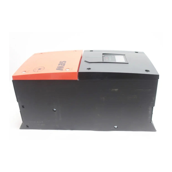
SEW MOVITRAC LTP-B Standard Inverter Manuals
Manuals and User Guides for SEW MOVITRAC LTP-B Standard Inverter. We have
1
SEW MOVITRAC LTP-B Standard Inverter manual available for free PDF download: Operating Instruction
SEW MOVITRAC LTP-B Operating Instruction (228 pages)
Standard inverters
Brand:
SEW
| Category:
Inverter
| Size: 11 MB
Table of Contents
Operating Instructions
1
Table of Contents
3
1 General Information
8
About this Documentation
8
Structure of the Safety Notes
8
Meaning of Signal Words
8
Structure of Section-Related Safety Notes
8
Structure of Embedded Safety Notes
8
Rights to Claim under Limited Warranty
9
Content of the Documentation
9
Exclusion of Liability
9
Product Names and Trademarks
9
Copyright Notice
9
2 Safety Notes
10
Preliminary Information
10
Operator's Duties
10
Target Group
10
Designated Use
11
Hoist Applications
11
Functional Safety Technology
12
Transport
12
Installation/Assembly
12
Restrictions of Use
13
Electrical Connection
13
Required Preventive Measure
13
Stationary Application
13
Protective Separation
14
Startup/Operation
14
3 Device Structure
15
Nameplate
15
Type Designation
15
Device Structure of the Standard Inverter
16
Inverters with Degree of Protection IP20/NEMA 1
16
Inverters with Degree of Protection IP66/NEMA 4X
17
Inverters with Degree of Protection IP55/NEMA 12K
18
4 Installation
19
General Information
19
Permitted Tightening Torques
20
Mechanical Installation
21
IP20 Housing: Installation and Installation Space
21
IP55/IP66 Housing: Installation and Control Cabinet Dimensions
22
Electrical Installation
23
Before Installation
23
Line Contactors
24
Mains Fuses
25
Operation on an IT System
26
Operation on a TN System with an RCD Switch (IP20)
27
Permitted Voltage Supply Systems
27
Help Card
27
Removing the Terminal Cover
28
Cable Gland Plate
30
Connecting and Installing the Braking Resistor
31
Motor Temperature Protection TF, TH, KTY84, PT1000
32
Multi-Motor Drive/Group Drive
33
Motor Cables and Fusing
33
Connecting AC Brakemotors
33
UL-Compliant Installation
34
Information Regarding UL
37
Electromagnetic Compatibility (EMC)
38
Overview of Signal Terminals
44
Communication Socket RJ45
47
Backup Mode
48
DC Link Connection
49
Wiring Diagram
49
Brake Control
51
5 Startup
52
User Interface
52
Keypads
52
Resetting Parameters to Default Settings
54
Key Combinations
54
Software LT Shell
55
MOVITOOLS ® Motionstudio Engineering Software
57
Automatic Measuring Procedure "Auto Tune
59
Startup for Motors
59
Startup for Asynchronous Motors with V/F Control
60
Startup for Asynchronous Motors with VFC Speed Control
60
Startup for Asynchronous Motors with VFC Torque Control
61
Startup of Synchronous Motors Without Encoder Feedback (PMVC Control)
62
Startup with LSPM Motors from SEW-EURODRIVE
63
Startup with Preset Motors from SEW-EURODRIVE
64
Startup of Control
65
Terminal Mode (Factory Setting) P1-12 = 0
65
Keypad Mode (P1-12 = 1 or 2)
66
PID Controller Mode (P1-12 = 3)
66
Master-Slave Mode (P1-12 = 4)
68
Fieldbus Mode (P1-12 = 5, 6 or 7)
69
Multimotion Mode (P1-12 = 8)
69
Hoist Function
70
General Information
71
Startup for Hoist Function
71
Hoisting Mode
72
Troubleshooting and Optimizing the Hoist Function
73
Fire Mode/Emergency Mode
74
Operation at 87 Hz Characteristic
75
Motor Potentiometer Function - Crane Application
75
Motor Potentiometer Operation
76
Terminal Assignment
77
Parameter Settings
77
Examples of Analog Input Scaling and Offset Setting
78
Example 1: Analog Input Scaling
78
Example 2: Analog Input Offset
79
Example 3: Analog Input Scaling and Offset
80
Fans and Pumps
81
Motor Potentiometer
81
3-Wire Control
82
Control Signal Source 3-Wire Control
82
6 Operation
83
Inverter Status
83
Static Inverter Status
83
Operating State of the Inverter
84
Status Displays of the Parameter Module
85
Fault Reset
85
Troubleshooting
86
Error History
86
Error Codes
87
7 Fieldbus Mode
92
General Information
92
Structure and Settings of Process Data Words
92
Communication Example
94
Parameter Settings for the Inverter
94
Connecting the Signal Terminals at the Inverter
95
Establishing a Canopen/Sbus Network
95
Connecting a Gateway or Controller (Sbus MOVILINK ® )
96
Specification
96
Electrical Installation
96
Startup at Gateway
97
Startup at a CCU
98
MOVI-PLC ® Motion Protocol (P1-12 = 8)
98
Modbus RTU
99
Specification
99
Electrical Installation
99
Register Allocation of the Process Data Words
100
Data Flow Example
101
Canopen
103
Specification
103
Electrical Installation
103
COB Ids and Functions in the Inverter
103
Supported Transmission Modes
104
Default Allocation Plan of Process Data Objects (PDO)
104
Data Flow Example
105
Table of Canopen-Specific Objects
106
Table of Manufacturer-Specific Objects
108
Emergency Code Objects
108
8 Service
109
Electronics Service by SEW-EURODRIVE
109
Extended Storage
109
Waste Disposal
110
9 Parameters
111
Overview of Parameters
111
Parameters for Realtime Monitoring (Read Only)
111
Parameter Register
116
Explanation of the Parameters
122
Parameter Group 1: Basic Parameters (Level 1)
122
Parameter Group 1: Servo-Specific Parameters (Level 1)
130
Parameter Group 2: Extended Parameter Setting (Level 2)
132
Parameter Group 3: PID Controller (Level 2)
142
Parameter Group 4: Motor Control (Level 2)
145
Parameter Group 5: Fieldbus Communication (Level 2)
151
Parameter Group 6: Extended Parameters (Level 3)
155
Parameter Group 7: Motor Control Parameters (Level 3)
161
Parameter Group 8: Application-Specific Parameters (Only LTX) (Level 3)
164
Parameter Group 9: Digital Inputs Defined by the User (Level 3)
166
10 Technical Data
173
Markings
173
Ambient Conditions
174
Technical Data
174
1-Phase System AC 200 - 240 V
175
3-Phase System AC 200 - 240 V
176
3-Phase System AC 380 - 480 V
180
Phase System AC 500 – 600 V
184
Input Voltage Ranges
187
Overload Capacity
187
Housing Variants and Dimensions
188
Housing Variants
188
Dimensions
189
Dimensions
190
Protection Function
192
11 Functional Safety (STO)
193
Integrated Safety Technology
193
Safe Condition
193
Safety Concept
193
Restrictions
196
Safety Conditions
197
Storage Requirements
197
Installation Requirements
197
Requirements on the External Safety Controller
199
Requirements for Safety Relays
200
Requirements on Startup
200
Requirements on Operation
200
Connection Variants
202
General Information
202
Disconnection of a Single Drive
203
Safety Characteristics
206
Signal Terminal Block for STO Safety Contact
206
12 Declaration of Conformity
207
Index
208
13 Address List
214
Advertisement
Advertisement
Related Products
SEW Movitrac B
Sew MOVITRAC B Series
SEW MOVIAXIS MX
SEW Movitrac MC07B
Sew MOVITRAC MC07B0003-2A3-4-00
Sew MOVITRAC MC07B0011-2A3-4-00
Sew MOVITRAC MC07B0015-2A3-4-00
Sew MOVITRAC MC07B0005-5A3-4-00/S0
Sew MOVITRAC MC07B0030-5A3-4-00/S0
Sew MOVITRAC MC07B0040-5A3-4-00/S0
SEW Categories
Controller
Inverter
DC Drives
Measuring Instruments
Control Unit
More SEW Manuals
Login
Sign In
OR
Sign in with Facebook
Sign in with Google
Upload manual
Upload from disk
Upload from URL