
Related Manuals for SEW MOVITRAC B Series


Summary of Contents for SEW MOVITRAC B Series
- Page 1 Drive Technology \ Drive Automation \ System Integration \ Services ® MOVITRAC System Manual Edition 02/2008 16601211 / EN...
- Page 2 Color Code System Color code system for catalogs and system manuals Our catalogs and system manuals are identified by a color code system at the back to make it easier to work with these publications. The short designation of the publication is indicated as well.
-
Page 3: Table Of Contents
Contents Contents Important Notes....................6 Structure of the safety notes ............... 6 Rights to claim under warranty ..............6 Exclusion of liability..................6 Safety Notes ......................7 General information ..................7 Target group ....................7 Designated use ................... 7 Transportation, storage................8 Installation.................... - Page 4 Contents Parameters......................86 Explanation of the parameters ..............86 Project Planning....................112 Schematic procedure ................112 Options for standard applications ............113 Description of applications ..............114 Speed-torque characteristic curve ............115 Motor selection..................116 Overload capacity ................... 118 Load capacity of the units at low output frequencies ......119 Selecting the braking resistor..............
- Page 5 9.10 Startup with PC and MOVITOOLS MotionStudio........202 9.11 Startup for MBG11A speed control module ..........202 9.12 Starting up pumps and fans of non-SEW motors........203 9.13 Starting the motor ................... 204 9.14 Parameter list..................208 Operation ......................219 10.1 Data backup....................
-
Page 6: Important Notes
You must comply with the information contained in these operating instructions to ensure safe operation of frequency inverters and to achieve the specified product characteristics and performance requirements. SEW-EURODRIVE assumes no liability for injury to persons or damage to equipment or property resulting from non-observance of these operating instructions. -
Page 7: Safety Notes
If you are unclear about any of the information in this documentation, or if you require further information, please contact SEW- EURODRIVE. -
Page 8: Transportation, Storage
2.3.1 Safety functions Frequency inverters from SEW-EURODRIVE may not perform any safety functions unless the inverters are subordinate to other safety systems. Use higher-level safety systems to ensure protection of equipment and personnel. -
Page 9: Electrical Connection
Safety Notes Electrical connection Electrical connection Observe the applicable national accident prevention guidelines when working on live frequency inverters (e.g. BGV A3). Electrical installation is to be carried out in compliance with pertinent regulations (e.g. cable cross sections, fusing, protective conductor connection). Additional information is contained in the documentation. -
Page 10: System Description Movitrac® B
System Description MOVITRAC® B MOVITRAC® B – compact, versatile and universal ® System Description MOVITRAC ® Compact and economical: MOVITRAC B – the next frequency inverter generation. ® MOVITRAC B – compact, versatile and universal The percentage of speed-variable AC drives with inverter technology is constantly increasing, and these units offer all options to optimize system and machine concepts to the process sequences in addition to machine-conserving drive technology. -
Page 11: System Overview Movitrac® B
System Description MOVITRAC® B System overview MOVITRAC® B ® System overview MOVITRAC 1x 200 ... 240 V 3x 200 ... 240 V 3x 380 ... 500 V Keypad Front option DBG60B keypad FBG11B Line choke ND... Line filter NF... Analog module FIO11B ®... -
Page 12: The Units At A Glance
System Description MOVITRAC® B The units at a glance The units at a glance ® Power supply Motor power Rated output MOVITRAC B type Size connection current 0.25 kW / 0.34 HP AC 1.7 A MC07B0003-2B1-4-00 0.37 kW / 0.50 HP AC 2.5 A MC07B0004-2B1-4-00 0.55 kW / 0.74 HP... -
Page 13: Functions / Features
System Description MOVITRAC® B Functions / features Functions / features ® MOVITRAC B frequency inverters are characterized by the following features: 3.4.1 Unit properties • Wide voltage range: – 230 V units for the voltage range 1 × AC 200 ... 240 V, 50/60 Hz –... - Page 14 System Description MOVITRAC® B Functions / features • Integrated keypad for displaying setpoints and setting parameters – 5-digit 7-segment display – 9 LEDs for displaying the selected symbols – 6 keys for operation – 1 setpoint generator for speed specification –...
- Page 15 System Description MOVITRAC® B Functions / features • Speed monitoring and monitoring of the motor and regenerative limit power. • 5 fault memories with all relevant operating data at the moment of the fault. • Standardized operation, parameter setting and identical unit connection technology ®...
-
Page 16: Movitools® Motionstudio
SCOPE ® SCOPE for MOVITOOLS MotionStudio is an oscilloscope program for SEW inverters. SCOPE allows you to optimize the drives yourself. The inverter records, for example, response functions to setpoint changes in real time. You can transfer this information to the PC and graphically display it. -
Page 17: Technical Data
Compatibility in Drive Engineering" from SEW-EURODRIVE. Compliance with limit classes C2 and C1 has been tested on a specified test setup. SEW-EURODRIVE can provide detailed information on request. The CE-mark on the nameplate indicates conformity with the low voltage directive 73/ 23/EEC. -
Page 18: General Technical Data
Technical Data General technical data General technical data ® The following technical data applies to all MOVITRAC B frequency inverters indepen- dent of size and power. ® MOVITRAC All sizes Interference immunity Complies with EN 61800-3 Interference emission with According to limit value class EMC-compliant installation •... - Page 19 Technical Data General technical data ® MOVITRAC All sizes Up to h ≤ 1000 m (3281 ft) without restrictions. Installation altitude At h ≥ 1000 m (3281 ft), the following restrictions apply: • from 1,000 m (3281 ft) to max. 4000 m (13120 ft): –...
-
Page 20: Movitrac® B Electronics Data
Technical Data MOVITRAC® B electronics data ® MOVITRAC B electronics data Function Terminal Designa- Default Data tion Setpoint input (differ- X10:1 REF1 +10 V, R = 3 k Lmin ential input) X10:2 AI11 (+) 0 ... +10 V (R > 200 k ) X10:3 AI12 (–) 0 ... - Page 21 Technical Data MOVITRAC® B electronics data Function Terminal Designa- Default Data tion Safety contact X17:1 DGND: Reference potential for X17:3 X17:2 VO24: : V = DC 24 V, only to supply X17:4 of the same unit; it cannot be used to supply other units.
-
Page 22: Technical Data Of Movitrac® B
Technical Data Technical data of MOVITRAC® B ® Technical data of MOVITRAC ® 4.4.1 Overview MOVITRAC 400 / 500 V 230 V Power supply connection 400 / 500 V / 3-phase Size Power [kW / 0.55 / 0.74 2.2 / 3.0 15 / 20 0.25 / 0.34 0.75 / 1.0... - Page 23 Technical Data Technical data of MOVITRAC® B 4.4.2 AC 400 / 500 V / 3-phase / size 0XS / 0.25 ... 0.37 kW / 0.34 ... 0.50 HP 54.5 (2.15) 163.5 (6.437) 6 (0.2) 149 (5.87) 49.5 (1.95) 6 (0.2) 159.5 (6.280) ®...
- Page 24 Technical Data Technical data of MOVITRAC® B 4.4.3 AC 400 / 500 V / 3-phase / size 0S / 0.55 ... 1.5 kW / 0.74 ... 2.0 HP 163.5 (6.437) 80 (3.1) 149 (5.87) 6 (0.2) 70 (2.8) 6 (0.2) 159.5 (6.280) ®...
- Page 25 Technical Data Technical data of MOVITRAC® B 4.4.4 AC 400 / 500 V / 3-phase / size 0L / 2.2 ... 4.0 kW / 3.0 ... 5.4 HP 163.5 (6.437) 80 (3.1) 6 (0.2) 149 (5.87) 70 (2.8) 6 (0.2) 159.5 (6.280) ®...
- Page 26 Technical Data Technical data of MOVITRAC® B 4.4.5 AC 400 / 500 V / 3-phase / size 2S / 5.5 ... 7.5 kW / 7.4 ... 10 HP 238 (9.37) 105 (4.13) 234 (9.21) 70 (2.8) 7 (0.3) ® MOVITRAC MC07B (3-phase supply system) 0055-5A3-4-00 0075-5A3-4-00...
- Page 27 Technical Data Technical data of MOVITRAC® B 4.4.6 AC 400 / 500 V / 3-phase / size 2 / 11 kW / 15 HP 130 (5.12) 229 (9.02) 105 (4.13) 225 (8.86) 6.5 (0.26) ® MOVITRAC MC07B (3-phase supply system) 0110-5A3-4-00 Part number 828 527 6...
- Page 28 Technical Data Technical data of MOVITRAC® B 4.4.7 AC 400 / 500 V / 3-phase / size 3 / 15 ... 30 kW / 20 ... 40 HP 200 (7.87) 251 (9.88) 105 (4.13) 247 (9.72) 7 (0.3) ® MOVITRAC MC07B (3-phase supply system) 0150-503-4-00 0220-503-4-00...
- Page 29 Technical Data Technical data of MOVITRAC® B 4.4.8 AC 400 / 500 V / 3-phase / size 4 / 37 ... 45 kW / 50 ... 60 HP 280 (11.0) 250 (9.84) 140 (5.51) 246 (9.69) 7 (0.3) ® MOVITRAC MC07B (3-phase supply system) 0370-503-4-00 0450-503-4-00...
- Page 30 Technical Data Technical data of MOVITRAC® B 4.4.9 AC 400 / 500 V / 3-phase / size 5 / 55 ... 75 kW / 74 ... 100 HP 280 (11.0) 330 (13.0) 140 (5.51) 7 (0.3) ® MOVITRAC MC07B (3-phase supply system) 0550-503-4-00 0750-503-4-00 Part number...
- Page 31 Technical Data Technical data of MOVITRAC® B 4.4.10 AC 230 V / 1-phase / size 0XS / 0.25 ... 0.37 kW / 0.34 ... 0.50 HP 54.5 (2.15) 163.5 (6.437) 6 (0.2) 149 (5.87) 49.5 (1.95) 6 (0.2) 159.5 (6.280) ®...
- Page 32 Technical Data Technical data of MOVITRAC® B 4.4.11 AC 230 V / 1-phase / size 0S / 0.55 ... 0.75 kW / 0.74 ... 1.0 HP 163.5 (6.437) 80 (3.1) 149 (5.87) 6 (0.2) 70 (2.8) 6 (0.2) 159.5 (6.280) ®...
- Page 33 Technical Data Technical data of MOVITRAC® B 4.4.12 AC 230 V / 1-phase / size 0L / 1.1 ... 2.2 kW / 1.5 ... 3.0 HP 163.5 (6.437) 80 (3.1) 6 (0.2) 149 (5.87) 70 (2.8) 6 (0.2) 159.5 (6.280) ®...
- Page 34 Technical Data Technical data of MOVITRAC® B 4.4.13 AC 230 V / 3-phase / size 0XS / 0.25 ... 0.37 kW / 0.34 ... 0.50 HP 54.5 (2.15) 163.5 (6.437) 6 (0.2) 149 (5.87) 49.5 (1.95) 6 (0.2) 159.5 (6.280) ®...
- Page 35 Technical Data Technical data of MOVITRAC® B 4.4.14 AC 230 V / 3-phase / size 0S / 0.55 ... 0.75 kW / 0.74 ... 1.0 HP 163.5 (6.437) 80 (3.1) 149 (5.87) 6 (0.2) 70 (2.8) 6 (0.2) 159.5 (6.280) ®...
- Page 36 Technical Data Technical data of MOVITRAC® B 4.4.15 AC 230 V / 3-phase / size 0L / 1.1 ... 2.2 kW / 1.5 ... 3.0 HP 163.5 (6.437) 80 (3.1) 6 (0.2) 149 (5.87) 70 (2.8) 6 (0.2) 159.5 (6.280) ®...
- Page 37 Technical Data Technical data of MOVITRAC® B 4.4.16 AC 230 V / 3-phase / size 1 / 3.7 kW / 5.0 HP 105 (4.13) 177 (6.97) 85 (3.3) 173 (6.81) 6 (0.2) ® MOVITRAC MC07B (3-phase supply system) 0037-2A3-4-00 Part number 828 506 3 INPUT Rated mains voltage...
- Page 38 Technical Data Technical data of MOVITRAC® B 4.4.17 AC 230 V / 3-phase / size 2 / 5.5 ... 7.5 kW / 7.4 ... 10 HP 130 (5.12) 229 (9.02) 105 (4.13) 225 (8.86) 6.5 (0.26) ® MOVITRAC MC07B (3-phase supply system) 0055-2A3-4-00 0075-2A3-4-00 Part number...
- Page 39 Technical Data Technical data of MOVITRAC® B 4.4.18 AC 230 V / 3-phase / size 3 / 11 ... 15 kW / 15 ... 20 HP 200 (7.87) 251 (9.88) 105 (4.13) 247 (9.72) 7 (0.3) ® MOVITRAC MC07B (3-phase supply system) 0110-203-4-00 0150-203-4-00 Part number...
- Page 40 Technical Data Technical data of MOVITRAC® B 4.4.19 AC 230 V / 3-phase / size 4 / 22 ... 30 kW / 30 ... 40 HP 280 (11.0) 250 (9.84) 140 (5.51) 246 (9.69) 7 (0.3) ® MOVITRAC MC07B (3-phase supply system) 0220-203-4-00 0300-203-4-00 Part number...
-
Page 41: Front Option Fbg11B Keypad
Error memory and error reset queries • Displaying and setting parameters • Back up and transfer of parameter sets • Easy-to-use startup menu for SEW and non-SEW motors ® • Manual control for MOVITRAC Features • 5-digit, 7-segment display / 6 buttons / 8 icons / setpoint control module •... -
Page 42: Fsc11B Communication Module
Technical Data FSC11B communication module FSC11B communication module The FSC11B communication module enables communication with other units. These ® ® may include: PC, operator terminals, MOVITRAC or MOVIDRIVE Part number 1820 716 2 ® ® Functions • Communication with PLC / MOVITRAC B / MOVIDRIVE / PC •... -
Page 43: Fio11B Analog Module
Technical Data FIO11B analog module FIO11B analog module Part number 1820 637 9 4.7.1 Description The FIO11B analog module adds the following interfaces to the basic version: • Setpoint input • Analog output • RS-485 interface • The options FIO11B and FSC11B are mounted on the same fastening place and therefore cannot be used simultaneously. -
Page 44: Dbg60B Keypad
Technical Data DBG60B keypad DBG60B keypad 4.8.1 Description MOVITRAC® The basic version of does not have a DBG60B keypad but has the option of an upgrade to include the plain text keypad. Keypad Language Part number DE/EN/FR/IT/ES/PT/NL (German / English / French / Ital- DBG60B-01 1 820 403 1 ian / Spanish / Portuguese /... - Page 45 Technical Data DBG60B keypad 4.8.3 Features • Illuminated plain text display, choice of 7 languages • Keypad with 21 keys • Can be connected via extension cable DKG60B (5 m (20 ft)) • Degree of protection IP40 (EN 60529) NOTE The DBG60B keypad option is connected to the FSC11B or FIO11B communication front option.
- Page 46 Technical Data DBG60B keypad 4.8.5 DBG60B housing dimension drawing The DBM60B option can be used to mount the DBG60B keypad in the control cabinet door, for example. The DBM60B option consists of housing in enclosure IP65 and a 5 m (20 ft) DKG60B extension cable.
-
Page 47: Parameter Module Ubp11A
Technical Data Parameter module UBP11A Parameter module UBP11A Part number: 823 933 9 Functional description: • Saving data from the inverter to the parameter module • Loading data back from the parameter module to the inverter • Operating status display •... -
Page 48: Mbg11A Setpoint Control Module
Technical Data MBG11A setpoint control module 4.10 MBG11A setpoint control module Functional description: • The MBG11A setpoint control module has 2 keys and a display. They make it possible to adjust the speed remotely in the range from -100 %... +100 % f (potentiometer f1). -
Page 49: Uws11A Interface Adapter Rs-232 / Rs-485 For Mounting Rail
Technical Data UWS11A interface adapter RS-232 / RS-485 for mounting rail 4.11 UWS11A interface adapter RS-232 / RS-485 for mounting rail Part number 822 689 X The FSC11B or FIO11B is required for connecting the UWS11A. Ambient temperature 0 ... 40 °C (32 ... 104 °F) Degree of protection IP20 Description... -
Page 50: Uws21B Interface Adapter Rs-232/Rs-485
Technical Data UWS21B interface adapter RS-232/RS-485 4.12 UWS21B interface adapter RS-232/RS-485 Part number 18204562 The FSC11B or FIO11B is required for connecting the UWS21B. Ambient temperature 0... 40 °C (32 ... 104 °F) Degree of protection IP20 Description The UWS21B option converts RS-232 signals, for example from the PC, into RS-485 signals. These RS-485 ®... -
Page 51: Bw Series Braking Resistors
Technical Data BW series braking resistors 4.14 BW series braking resistors 4.14.1 General information ® BW series braking resistors are adapted to the MOVITRAC B inverter series. The type of cooling is KS = self-cooling (air ventilation). The resistor surfaces will heat up under a load of P . - Page 52 Technical Data BW series braking resistors 4.14.3 Flat design The flat-design resistors have degree of protection IP54 and are equipped with internal thermal overload protection (cannot be replaced). Depending on their type, you can in- stall the resistors as follows: •...
- Page 53 • A thermal overcurrent relay is integrated in the BW...-P braking resistor SEW-EURODRIVE recommends also protecting the wire and grid resistors against overload using a bimetallic relay with trip characteristics of trip class 10 or 10A (in (→ following tables).
- Page 54 Technical Data BW series braking resistors 230 V Type BW027- BW027- BW018- BW018- BW018- BW012- BW012- BW012- Part number 822 422 6 822 423 4 – – – 821 680 0 – – Type BW..-T part number – – 1820 416 3 1820 138 5 1820 139 3 –...
- Page 55 Technical Data BW series braking resistors 400 V Type BW100-006 BW168 BW268 BW147 BW247 BW347 Part number 821 701 7 820,604 X 820 715 1 820 713 5 820 714 3 820 798 4 Type BW..-T part number 1820 419 8 1820 133 4 1820 417 1 1820 134 2...
- Page 56 Technical Data BW series braking resistors 4.14.5 Dimensions of BW braking resistors Flat-design Flat-design resistors: The connecting lead is 500 mm (19.69 in) long. The scope of delivery includes four M4 threaded bushes each of type 1 and 2. (0.47) Type Main dimensions [mm (in)] Fastening parts [mm (in)]...
- Page 57 Technical Data BW series braking resistors Grid resistors Type Main dimensions [mm (in)] Fastening parts [mm (in)] Weight [kg (lb)] A BW..-T b/c/e BW012-025 295 (11.6) – 260 (10.2) 490 (19.3) 270 (10.6) 380 (15.0) – 10.5 (0.413) 8.0 (18) BW012-025-P 295 (11.6) –...
-
Page 58: Touch Guard Bs
Technical Data Touch guard BS 4.15 Touch guard BS Touch guard dimension drawing: [1] Grommet [2] Support rail mounting Type Main dimensions [mm (in)] Mounting dimensions [mm (in)] BS-003 60 (2.4) 160 (6.30) 146 (5.75) 125 (4.92) 40 (1.6) 20 (0.8) 6 (0.2) 17.5 (0.689) BS-005... -
Page 59: Submounting Fkb11/12/13B Flat-Design Resistors
Technical Data Submounting FKB11/12/13B flat-design resistors 4.17 Submounting FKB11/12/13B flat-design resistors FKB..B is used for submounting flat-design resistors under the inverter. Type Part number Size Braking resistor 230 V 400/500 V FKB11B 1820 728 6 FKB12B 1820 729 4 BW027-003 BW072-003 FKB13B 1820 730 8... -
Page 60: Support Rail Mounting Fhs11B/12B/13B
Technical Data Support rail mounting FHS11B/12B/13B 4.18 Support rail mounting FHS11B/12B/13B ® The FHS is used for support rail mounting of MOVITRAC B frequency inverters and for the submounting of flat-design resistors. Type Part number Size Braking resistor 230 V 400/500 V FHS11B 1820 724 3... -
Page 61: Line Chokes Nd
Technical Data Line chokes ND 4.19 Line chokes ND The line choke assists in overvoltage protection. The line choke limits the charging current when several inverters are connected together in parallel on the input end with shared mains contactors. ND line filters have cRUus approval independent of the ®... - Page 62 Technical Data Line chokes ND 4.19.1 Dimension drawing for ND 010-301 / ND 020-151 Type Main dimensions [mm (in)] Mounting dimensions [mm (in)] Weight [kg (lb)] ND 010-301 90 (3.5) 100 (3.94) 80 (3.1) 70 (2.8) 64 (2.5) 52 (2.0) 4.4 (0.17) 7.4 (0.29) 1.4 (3.1)
-
Page 63: Nf Line Filter
Technical Data NF line filter 4.20 NF line filter The line filter suppresses interference emissions on the line side of inverters. The ambient temperature range is –25 ... +45 °C (–13 ... 113 °F). The degree of protection is IP20 (EN 60529). NF line filters have cRUus approval independent of the ®... - Page 64 Technical Data NF line filter Dimension drawing for line filter [mm (in)]: Line filter Main dimensions type NF009-503 195 (7.68) 55 (2.2) NF014-503 225 (8.86) 80 (3.1) NF018-503 50 (2.0) 255 (10.0) NF035-503 275 (10.8) 60 (2.4) NF048-503 315 (12.4) 100 (3.94) NF063-503 260 (10.2)
-
Page 65: Ulf11A Folding Ferrites
Technical Data ULF11A folding ferrites 4.21 ULF11A folding ferrites Folding ferrites are used to reduce intereference emitted from the mains cable. Only use folding ferrites with single-phase units. The delivery scope contains 3 folding ferrites, which much be installed according to the installation instructions. - Page 66 Technical Data HD series output chokes HD dimension drawing 001 / 002 / 003 [mm (in)]: Output Main dimensions Installation Inside Hole choke type dimensions diameter dimension HD001 121 (4.76) 64 (2.5) 131 (5.16) 80 (3.1) 50 (2.0) 50 (2.0) 5.8 (0.23) HD002 66 (2.6)
- Page 67 Technical Data HD series output chokes Dimension drawing for HD100 / HD101: 208.5 (8.209) 80 (3.1) 45 (1.8) ® Output choke MOVITRAC type HD100 Size 0S 226 (8.90) 248 (9.76) 196 (7.72) HD101 Size 0L 314.5 (12.38) 336.5 (13.25) 284.5 (11.20) System Manual V2 –...
-
Page 68: Emc-Module Fke12B/13B
Technical Data EMC-module FKE12B/13B 4.23 EMC-module FKE12B/13B Using the EMC module, you can reach limit class C1 (B) on the input and output sides. The EMC module is designed for 100 % operation and 125 % operation. Type FKE12B FKE13B Part number 829 590 5 829 591 3... -
Page 69: Hf Output Filter
Technical Data HF output filter 4.24 HF output filter SEW output filters of the HF type are sine filters. Sine filters smoothen the output voltage of inverters. Use output filters in the following cases: • In group drives (several motor leads in parallel); the discharge currents in the motor cables are suppressed. - Page 70 0220/0300 ® 1) Approved to UL/cUL in conjunction with MOVITRAC frequency inverters. SEW-EURODRIVE will provide a certificate on request. 2) A reduction of 6 % I per 10 Hz applies above f = 60 Hz for the rated through current I 3) Only applies for operation without V connection.
- Page 71 Technical Data HF output filter HF...-503 dimension drawing [mm (in)]: MOVIDRIVE ® MOVIDRIVE ® MOVIDRIVE ® Type Main dimensions HF008 / 015 / 022 / 030-503 80 (3.1) 286 (11.3) 176 (6.93) HF040 / 055 / 075-503 135 (5.31) 296 (11.7) 216 (8.50) Type Installation dimensions...
- Page 72 Technical Data HF output filter HF...-403 dimension drawing [mm (in)]: Type Main dimensions Standard mounting position C/C1 HF023-403 365/390 (14.4/ 145 (5.71) 284 (11.2) 268 (10.6) 60 (2.4) 15.4) HF033-403 385/400 (15.2/ HF047-403 190 (7.48) 300 (11.8) 284 (11.2) 80 (3.1) 15.7) Type Horizontal mounting...
-
Page 73: Fieldbus Connection
The FIO11B module cannot be used for connecting. ® In general, you can also connect and operate other SEW units (such as MOVIDRIVE inverters) using the SBus. There are two different versions of gateway functionality: •... - Page 74 Technical Data Fieldbus connection Gateways are available for the following bus systems for connection to fieldbuses. Separate housing Integrated in inverter PROFIBUS DFP21B / UOH11B MC07B.../FSC11B/DFP21B DeviceNet DFD11B/UOH11B MC07B.../FSC11B/DFD11B EtherCAT DFE24B/UOH11B MC07B.../FSC11B/DFE24B PROFINET DFE32B/UOH11B MC07B.../FSC11B/DFE32B EtherNet/IP DFE33B / UOH11B MC07B.../FSC11B/DFE33B ®...
- Page 75 Technical Data Fieldbus connection Dimension drawing for UOH 4.5 (0.18) 30 (1.2) 22.5 (0.886) 100 (3.94) System Manual V2 – MOVITRAC® B...
- Page 76 Technical Data Fieldbus connection 4.25.2 Fieldbus interface DFP21B for PROFIBUS ® Description The MOVITRAC B frequency inverter enables you to use the DFP21B option to con- nect to higher-level automation systems via PROFIBUS DP and DP-V1 thanks to its powerful, universal fieldbus interface. Refer to the publication "Fieldbus interface DFP21B PROFIBUS DP-V1"...
- Page 77 Technical Data Fieldbus connection 4.25.3 Fieldbus Interface DFD11B for DeviceNet ® Description The MOVITRAC B frequency inverter together with the DFD11B option and its high- performance universal fieldbus interface enable the connection to higher-level automa- tion systems via the open and standardized DeviceNet fieldbus system. Refer to the publication "DFD11B DeviceNet Fieldbus Interface"...
- Page 78 Technical Data Fieldbus connection 4.25.4 Fieldbus interface DFE24B for EtherCAT ® Description The MOVITRAC B frequency inverter enables you to use the DFE24B option to connect to higher-level automation systems via EtherCAT thanks to its powerful, univer- sal fieldbus interface. Refer to the publication "DFE24B EtherCAT Fieldbus Interface"...
- Page 79 100 Mbaud in full duplex process Connection 2 x RJ45 with internal switch and auto crossing technology Addressing 4 byte IP address or MAC-ID (00:0F:69:xx:xx:xx) Manufacturer ID 010A (vendor ID) GSD file name GSML-V2.1-SEW-DFE-DFS-2Ports-YYYYMMTT.xml System Manual V2 – MOVITRAC® B...
- Page 80 Technical Data Fieldbus connection 4.25.6 DFE33B fieldbus interface for EtherNet/IP ® Description The MOVITRAC B frequency inverter enables you to use the EtherNet/IP DFE33B option to connect to higher-level automation systems via EtherNet/IP thanks to its powerful, universal fieldbus interface. Refer to the publication "DFE33B EtherNet/IP Fieldbus Interface"...
- Page 81 Technical Data Fieldbus connection ® 4.25.7 Fieldbus interface DFS11B for PROFIBUS / PROFIsafe ® Description The MOVITRAC B frequency inverter enables you to use the DFS11B option to ® connect to higher-level automation systems via PROFIBUS with PROFIsafe thanks to its powerful, universal fieldbus interface.
- Page 82 4 byte IP address or MAC-ID (00:0F:69:xx:xx:xx) F address 1 ... 1022, adjustable via DIP switches Manufacturer ID 010A (vendor ID) GSD file name GSML-V2.1-SEW-DFE-DFS-2Ports-YYYYMMTT.xml NOTE ® Safety-oriented applications are implemented using PROFIsafe interfaces. ® Refer to the publication "DF21B PROFINET with PROFIsafe Fieldbus Interface"...
-
Page 83: Movi-Plc
IEC 61131-3 and PLCopen standards for the first time. The DHP11B option is integrated ex works (not in size 0XS) or supplied in a separate UOH housing. Only SEW EURODRIVE can carry out an expansion of the unit with this option. ®... - Page 84 Maximum 32 process data System bus • 2 system buses (CAN) for control of 12 inverters and CANopen I/O modules • CAN layer 2 (SCOM cyclic, acyclic) or via the SEW ® MOVILINK protocol • Baud rate: 125 kBaud ... 1 MBaud •...
-
Page 85: Uwu52A Switched-Mode Power Supply
Technical Data UWU52A switched-mode power supply 4.27 UWU52A switched-mode power supply UWU52A switched-mode power supply Part number 188 181 7 Input voltage 1 × AC 110 V ... AC 240 V Voltage range AC 95 ... 265 V, DC 110 … 300 V Frequency 50/60 Hz Maximum no-load current... -
Page 86: Parameters
Parameters Explanation of the parameters Parameters As a rule, you only set the parameters during startup and if servicing is required. You ® can set the MOVITRAC B parameters in various ways: • With the keypad ® • With the MOVITOOLS MotionStudio program on a PC via the RS-485 interface •... - Page 87 Parameters Explanation of the parameters Name Description Output current [A] Apparent current at the inverter output, displayed in AC A. Status displays Inverter status Status of the unit output stage: • INHIBITED • ENABLED Operating status The following operating states are available: •...
- Page 88 Parameters Explanation of the parameters Name Description Fault memory ® 080 ... Fault t-0 ... Fault t-4 (FBG11B The unit saves the following information when an error occurs. MOVITOOLS keypad: fault t-0 only) MotionStudio can display this information if required: •...
- Page 89 Parameters Explanation of the parameters Name Description Setpoint source 11 / Frequency setpoint input / Fixed setpoint The frequency at binary input DI04 specifies the setpoint. Set the value with the P102 Frequency scaling parameter. You can influence the value with P110 AI1 scaling.
- Page 90 Parameters Explanation of the parameters Name Description Control signal source 0 / Terminals The binary inputs determine the control. 1 / RS-485 The RS-485 interface and the binary inputs determine the control. 3 / SBus The system bus and the binary inputs determine the control. 4 / 3-Wire Control The 3-wire control principle determines the control.
- Page 91 Parameters Explanation of the parameters Name Description FI1 reference 0 / n 1 / n reference Setpoint reference speed Setting range: 0 ... 3000 ... 6000 rpm for frequency input FI1 reference and analog inputs AI1 and AI2 Wire breakage detection Wire breakage detection is only available in operating mode 4 ...
- Page 92 Parameters Explanation of the parameters Name Description Analog input 1 (0 ... +10 V) The analog input can be configured using a characteristic curve. AI1 operating mode Maximum speed Setpoint reference speed Speed Normalized setpoint Input value input value Normalized setpoint in rpm Normalization charact.
- Page 93 Parameters Explanation of the parameters Name Description AI1 voltage offset Setting range: –10 V ... 0 ... +10 V (up to firmware 12) The zero passage of the setpoint characteristic curve can be moved along the U axis. P302/P312 Reference point with positive offset (P113) U offset...
- Page 94 Parameters Explanation of the parameters Name Description Analog input AI2 / FBG Setpoint generator (option) Analog input AI2 is only available with the optional analog module FIO11B. Maximum speed Speed Normalized setpoint Input value input value Normalized setpoint in rpm Normali- charact.
- Page 95 Parameters Explanation of the parameters Name Description AI2 characteristic curve x1 Setting range –100 % ... 0 ... +100 % (–10 V ... 0 ... +10 V) AI2 characteristic curve y1 Setting range –100 % ... 0 ... +100 % (–n ...
- Page 96 Parameters Explanation of the parameters Name Description 139 / 149 Ramp monitoring 1 / 2 Setting range: YES / NO If you set the deceleration ramps to a value that is a lot shorter than can be physically accomplished in this system, the turning drive will be stopped after expiration of the monitoring time.
- Page 97 Parameters Explanation of the parameters Name Description PI controller 0 / Off PI controller deactivated. 1 / Normal PI controller switched on normally. 2 / Inverted PI controller switched on inverted. P-gain Setting range 0 ... 1 ... 64 I-component Setting range 0 ...
- Page 98 The function cannot be deactivated. The factory setting depends on the rated ® power of the MOVITRAC B and will be added to the rated current of the SEW motor with the same rating. At 150 % rated motor current, the inverter switches off after 5 minutes.
- Page 99 Parameters Explanation of the parameters Name Description Reference signals The following reference values are used for recording and signaling certain operating states. All signals of parameter group 4__ can be output via binary outputs. The signals are valid if the inverter has signaled ready after switch-on and there is no fault. Speed reference signal The inverter issues the signal "1"...
- Page 100 Parameters Explanation of the parameters Name Description Imax signal (in preparation) Signal if the inverter has reached the current limitation. Hysteresis Setting range 0 ... 5 ... 50 % I Delay time Setting range 0 ... 1 ... 9 s Signal = "1"...
- Page 101 Parameters Explanation of the parameters Name Description Response to drive vibration / Factory setting: Display error warning Once the drive vibration sensor signals a warning, the inverter will respond with the set response. Response to drive vibration / Factory setting: Rapid stop / warning fault Once the drive vibration sensor signals a fault, the inverter will respond with the set response.
- Page 102 Parameters Explanation of the parameters Name Description Binary outputs (for controlling the brake rectifier use only binary output DO02) Effect of 0 signal 1 signal 0: No function: – – 1: /Fault: Collective fault signal – 2: Ready: Not ready ready 3: Output stage on: Unit inhibited...
- Page 103 Parameters Explanation of the parameters Name Description Analog output AO1 0 / No function The value 0 % evaluated by the characteristic curve is displayed. 1 / Ramp generator input (amount) / 100 % corresponds to 3000 rpm Setpoint speed at the input of the internal ramp generator 2 / Setpoint speed (amount) / 100 % corresponds to 3000 rpm Valid setpoint speed (output ramp generator or correcting variable of the higher-level controller)
- Page 104 • A single-phase motor phase failure cannot always be detected reliably. • SEW-EURODRIVE strongly recommends activating speed monitoring. • Prerequisite for correct performance of the hoist function: Motor brake controlled by the inverter. • Speed monitoring is set by changing parameters 500 / 502 and 501 / 503. The sagging of hoists cannot be avoided safely when monitoring is deactivated or the delay time is set too long.
- Page 105 Startup of an SEW motor: The IxR value is set for an SEW motor at operating temperature. This value has to be reduced if flying start takes place with a cold motor.
- Page 106 Parameters Explanation of the parameters Name Description 720 / 723 Setpoint stop function 1 / 2 off / OFF on / ON 721 / 724 Stop setpoint 1 / 2 0 ... 30 ... 500 [rpm] 722 / 725 Start offset 1 / 2 0 ...
- Page 107 Parameters Explanation of the parameters Name Description Master/slave function (in preparation) The master-slave function allows for implementing automatical functions such as speed synchronization, shared load and torque control (slave). The RS-485 interface or the system bus interface can be used as the communica- tion link.
- Page 108 Parameters Explanation of the parameters Name Description Energy-saving function off / OFF on / ON Unit functions Setup Short menu (FBG11B only) long short Use P800 to switch from the factory set short menu to the detailed parameter menu. Language DBG60B Language selection only for DBG60B keypad.
- Page 109 B units are always set to the address 0 on delivery. To avoid prob- lems during data exchange in serial communication with several inverters, SEW-EURODRIVE recommends that you do not use address 0. RS-485 group address Setting range 100 ... 199 RS-485 timeout interval Setting range 0 ...
- Page 110 Parameters Explanation of the parameters Name Description Scaling actual speed value Scaling actual speed value defines a user-specific display parameter P001 User display. For example, the user display is to be shown in 1/s. Such a setting requires a scaling factor of 1/60. This means the numerator scaling factor has to be set to 1 and the denominator scaling factor to 60.
- Page 111 B units are always set to the address 0 on delivery. To avoid prob- lems during data exchange in serial communication with several inverters, SEW-EURODRIVE recommends that you do not use address 0. SBus group address Setting range 0 ... 63 ®...
-
Page 112: Project Planning
Project Planning Schematic procedure Project Planning Schematic procedure Clarification of → • Technical data and requirements • Basic conditions • System interfacing ↓ Calculating the relevant application data • Stationary, dynamic, regenerative power • Speed ↓ Gear unit selection Determine •... -
Page 113: Options For Standard Applications
Project Planning Options for standard applications Options for standard applications Refer to the following table for available options for simple applications. Conditions for simple applications: • Vertical movement: Braking time is less than 25 % of cyclic duration factor CDF and no longer than 30 s. -
Page 114: Description Of Applications
Project Planning Description of applications Description of applications 6.3.1 Project planning for trolleys The motor load in the dynamic sections determines the peak motor power to be dimen- sioned. The thermal load determines the required continuous motor power. Refer to the travel cycle for determining the thermal load. -
Page 115: Speed-Torque Characteristic Curve
Project Planning Speed-torque characteristic curve • S1 (100 % cdf): Select the motor power of the next higher motor type than the selected inverter power, e.g. for lengthy upwards travel or continuous elevators. • S3 (40 % cdf): Select the motor power according to the selected inverter power. Activate the hoisting function by selecting operating mode P700 = VFC &... -
Page 116: Motor Selection
Project Planning Motor selection Motor selection 6.5.1 Basic recommendations • Only use motors with at least Thermal class F. • Use the TF thermistor or TH bimetallic switch. • Preferably use 4-pole motors. This applies particularly if you are operating gearmotors with a high oil filling level because of their vertical mounting position. - Page 117 The 4-pole motors (1500 rpm) are included ® in the factory settings of MOVITRAC B. Smaller motors can deteriorate the control behavior. ® MOVITRAC Rated power P SEW motor Speed [rpm] at 50 Hz 3000 1500 Speed [rpm] at 60 Hz 3600 1800 MC07B0003-...-4-00 0.25 kW (0.34 HP)
-
Page 118: Overload Capacity
Project Planning Overload capacity Overload capacity ® MOVITRAC B frequency inverters permanently calculate the load on the inverter output stage (unit utilization). They can output the maximum possible power in every operating status. The permitted continuous output current depends on: •... -
Page 119: Load Capacity Of The Units At Low Output Frequencies
Project Planning Load capacity of the units at low output frequencies Load capacity of the units at low output frequencies ® The thermal model in MOVITRAC B implements dynamic limiting of the maximum output current. Consequently, the thermal model only permits less than 100 % output current at output frequencies less than 2 Hz if the capacity utilization is high. -
Page 120: Selecting The Braking Resistor
Project Planning Selecting the braking resistor Selecting the braking resistor HAZARD! The supply cables to the braking resistor carry a high DC voltage (ca. DC 900 V). Severe or fatal injuries from electric shock. • The braking resistor cables must be suitable for this high DC voltage. •... - Page 121 Project Planning Selecting the braking resistor The following table lists the peak braking power levels that are possible for the differ- ent resistance values. Resistance [ ] Peak braking power [KW] 400 / 500 V units 230 V units – 13.0 –...
- Page 122 Project Planning Selecting the braking resistor Calculation Given: example • Average braking power: 0.25 kW • Brake ramp: 2 s • 200 brake applications per hour Approach: Calculating energy from the power of the brake ramp: × = 0 25 ×...
- Page 123 Project Planning Selecting the braking resistor Overload factor for Overload factor dependent on the cycle duration factor for wire resistors: wire resistors 100% ED [%] Cyclic duration factor 15 % 25 % 40 % 60 % 80 % 100 % Overload factor K 1.12 Overload factor for...
-
Page 124: Connecting Ac Brakemotors
For detailed information about the SEW brake system, refer to the "Gearmotors" catalog, which you can order from SEW-EURODRIVE. SEW brake systems are disc brakes with a DC coil that release electrically and brake using spring force. A brake rectifier provides the brake with DC voltage. -
Page 125: Mains And Motor Connection
The startup function in the FBG11B keypad and in the MotionStudio software sets the brake parameters for the 2-pole and 4-pole motors from SEW-EURODRIVE. The brake parameters (P73_) must be set manually in the case of SEW-EURODRIVE motors with a higher number of poles and non-SEW motors. - Page 126 Project Planning Mains and motor connection 6.10.2 Mains contactors and input fuses Input contactor • Only use input contactors of utilization category AC-3 (EN 60947-4-1). Mains activations • Ensure a minimum time of 120 s between two mains activations for AC 230 V / single-phase units.
- Page 127 Smallest bending space [mm] Wires per connection terminal 10 ... 16 Recommendation If single-core copper cables with PVC insulation routed in cable ducts are used, SEW- for standard instal- EURODRIVE proposes the following cable cross-sections and fuses for an ambient lation, metric temperature of 25 °C and rated mains currents of 100% of the rated inverter current:...
- Page 128 Project Planning Mains and motor connection ® MOVITRAC B 3 × 230 V 0037 0055 0075 0110 0150 0220 0300 Fuses F11/F12/F13 25 A 25 A 35 A 50 A 63 A 80 A 100 A Supply system cable L1/L2/ 4 mm 4 mm 6 mm...
- Page 129 Project Planning Mains and motor connection Recommendation for standard installation, USA NEC ® MOVITRAC B 1 × 230 V 0003 0004 0005 0008 0011 0015 0022 1-phase Line protection / gL16 / K16 / gL25 / K25 / D20 Supply system AWG16 AWG12 lead...
- Page 130 Project Planning Mains and motor connection ® MOVITRAC B 400 / 500 V 0370 0450 0550 0750 Size Fuses F11/F12/F13 90 A 110 A 150 A 175 A Supply system cable L1/L2/ AWG4 AWG3 AWG1 AWG2/0 PE conductor AWG8 AWG6 AWG6 AWG6 Motor cable U/V/W...
- Page 131 Project Planning Mains and motor connection 6.10.5 Voltage drop Select the cable cross-section of the motor cable so the voltage drop is as small as possible. An excessively high voltage drop means that the full motor torque is not achieved. You can determine the expected voltage drop using the following tables.
-
Page 132: Multi-Motor Drive/Group Drive
The motors in a group must not be more than 3 type sizes apart. 6.11.4 Output filter For groups with more than 3 ... 4 motors, SEW-EURODRIVE recommends to use an HF output filter. An output filter HF... is required if the maximum motor cable length (l given in the table is exceeded. -
Page 133: Line Chokes
Project Planning Line chokes 6.12 Line chokes 6.12.1 1-phase Use is required under the following circumstances: • Mains inductances of less than 100 μH per branch • Using line chokes is required when operating several units that are switched on simultaneously. - Page 134 Project Planning Electromagnetic compatibility EMC 6.13.1 Interference immunity ® MOVITRAC B meets the minimum requirements stipulated in EN 61800-3 with regard to interference immunity. 6.13.2 Interference emission ® The interference emission of MOVITRAC B was tested using standard equipment. The limit values complied with allow the units to be used in both the industrial and private sphere.
- Page 135 IT systems") to reduce earth-leakage currents in the inverter. When the suppression capacitors are deactivated, the EMC filter is no longer active. SEW-EURODRIVE recommends that you do not use earth-leakage circuit breakers and instead choose other measures to ensure protection of personnel (e.g. according to EN 61800-5-1, EN 50178, EN 60204-1, etc.).
-
Page 136: Hf Output Filters
• Considerable noise (magnetostriction) may occur in the output filter especially if operating with f = 4 kHz. In environments susceptible to noise, SEW- EURODRIVE recommends operation with f = 12 kHz (or 16 kHz) and V DC link connection. - Page 137 Project Planning HF output filters 6.14.3 U link Operation without V connection: DC link • Approved only for PWM frequency 4 kHz or 8 kHz. X2/3 Operation with V connection: DClink Connection of inverter terminal + R with HF…-503 terminal V5 or HF…-403 terminal 7 NOTES •...
- Page 138 Project Planning HF output filters The procedure for selecting the PWM frequency and checking the inverter is summarized in the following figure. Selecting PWM frequency Noise sensitive and V connection DClink environment in which HF is used (not motor!) Motor cable type Shielded Unschielded Length of motor cable...
-
Page 139: Electronics Cables And Signal Generation
Project Planning Electronics cables and signal generation 6.15 Electronics cables and signal generation 6.15.1 Cable type The electronic terminals are suitable for: • Cross sections up to 1.5 mm (AWG16) without conductor end sleeves • Cross sections up to 1.0 mm (AWG17) with conductor end sleeves Use shielded cables as standard. - Page 140 Project Planning External voltage supply DC 24 V ® DC 24 V power demand of MOVITRAC 2)3) Size Basic unit power DBG60B FIO11B Fieldbus option DHP11B demand 0 MC07B…-00 0 MC07B…-S0 12 W 1, 2S, 2 17 W 4.5 W 23 W 4, 5 25 W...
-
Page 141: Parameter Set Switchover
Project Planning Parameter set switchover 6.17 Parameter set switchover This function is used to operate two motors on one inverter using two different parameter sets. The parameter set is switched over via binary input or fieldbus. A binary input must be programmed to the "Parameter set switchover"... -
Page 142: Priority Of The Operating Statuses And Interrelation Between Control Signals
Project Planning Priority of the operating statuses and interrelation between control signals 6.18 Priority of the operating statuses and interrelation between control signals 6.18.1 Priority of operating states The following illustration shows the priority of operating states: Priority high Controller inhibit Rapid stop Stop Enable... -
Page 143: Pi Controller
Project Planning PI controller 6.19 PI controller You can use the implemented PI controller for temperature control, pressure control or other applications. The PI controller can be switched on and off. Structural diagram showing installation of the PI controller P250 PI controller Normal Inverted P251 P-gain... - Page 144 Project Planning PI controller 6.19.2 Setpoint selection The following settings are possible as the setpoint source. You can select the setpoint source with parameter P100. • Unipolar / Fixed setpoint: The setpoint zero applies as long as no setpoint is selected.
- Page 145 Project Planning PI controller 6.19.3 Actual value detection The unipolar input AI1 is the actual value input. You can set the operating mode for the actual value using P112 AI1 operating mode (see also parameters 116 … 119): • 0 ... 10 V: The following applies to operation as a voltage input: 0 ...
-
Page 146: Application Examples
Project Planning Application examples 6.20 Application examples All application examples presented here assume that the unit has been started up correctly in accordance with the "Startup" section. 6.20.1 External setpoint potentiometer The external setpoint potentiometer is not effective when manual operation is active. Connect an external setpoint potentiometer as follows: The resistance value of the external setpoint potentiometer R must be ≥... - Page 147 Project Planning Application examples Setpoint X1 P116 X2 P118 Setpoint Diagram source Y1 P117 Y2 P119 speed 100% / n 50 % / n – n 100 % Bipolar –n / +n –100 % 100 % 10 V 0 1/min 100% / 10 V -50 % / n -100% / n...
- Page 148 Project Planning Application examples 6.20.3 Speed-controlled agitator In this application, you can control the speed using the FBG speed control module. The keypad is used to control: • Reset • Start • Stop • Speed control. Select the "FGB speed control module" icon to operate the agitator. Parameters Adapt the following parameters for the agitator: •...
- Page 149 Project Planning Application examples 6.20.4 Positioning a trolley Principle Positioning a trolley with rapid speed and creep speed, and position detection using proximity sensors. The emergency off function must be guaranteed using a separate safety circuit. Install a braking resistor. Perform a startup for the VFC operating mode.
- Page 150 Project Planning Application examples Terminals • Rapid speed: DI04 = 1 and DI05 = 1 • Slow speed: DI04 = 1 and DI05 = 0 Assign the electronics terminal strip with • DI01 = CW/stop • DI02 = CCW/Stop • DI03 = Enable •...
- Page 151 Project Planning Application examples 6.20.5 PI controller Following a diagram showing the basic structure of the control system with a PI control- ler, taking the example of a pressure control system. ® MOVITRAC B Control Frequency Speed deviation Current/voltage Torque Pressure PI controller Motor...
-
Page 152: Unit Design
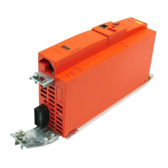
Unit design Size 0XS / 0S / 0L Unit design Size 0XS / 0S / 0L [17] [16] [15] [14] [13] [11] [12] [10] [18] [1] PE connection [2] X1: Power supply connection: 3-phase: L1 / L2 / L3 1-phase: L / N [5] X2: Motor connection U / V / W / Brake connection +R / –R [7] X17: Safety contact for safe stop (only MC07B...-S0: sizes 0S / 0L, 400 / 500 V) [9] X13: Binary outputs... -
Page 153: Size 1 / 2S / 2
Unit design Size 1 / 2S / 2 Size 1 / 2S / 2 [16] [15] [14] [13] [12] [11] [10] [1] X1: Power supply connection 3-phase: L1 / L2 / L3 / PE screw [3] X4: DC link connection –U / +U [4] X2: Motor connection U / V / W / PE screw [5] X3: Braking resistor connection R+ / R–... -
Page 154: Size 3
Unit design Size 3 Size 3 [16] [15] [14] [13] [12] [11] [10] [1] X2: PE connection [2] X1: Power supply connection 3-phase: 1/L1 / 2/L2 / 3/L3 [3] X4: DC link connection –U / +U [4] X2: PE connection [5] X2: Motor connection U (4) / V (5) / W (6) [6] X3: Braking resistor connection R+ (8) / R–... - Page 155 Unit design Size 4 / 5 Size 4 / 5 [16] [15] [14] [13] [12] [11] [10] [1] X2: PE connection [2] X1: Power supply connection 3-phase: 1/L1 / 2/L2 / 3/L3 [3] X4: DC link connection –U / +U and PE connection [4] X2: PE connection [5] X2: Motor connection U (4) / V (5) / W (6)
-
Page 156: Unit Designation / Nameplate
Unit design Unit designation / nameplate Unit designation / nameplate MC 07 B 0004- 2 B 1- 4- 00 00 = Standard Design S0 = Safe stop Quadrants 4 = 4Q (with brake chopper) Connection type 3 = 3-phase / 1 = 1-phase 0 = No radio interference suppression Radio interference sup- A = Radio interference suppression C2... -
Page 157: Installation
Installation Installation notes Installation Installation notes NOTE Comply with the safety notes during installation. 8.1.1 Mounting the front options Observe the following sequence when mounting the front options: • To mount the FBG11B [A] keypad, first insert it on top of the housing [1]. Next, press the socket on the keypad onto the connector of the unit [2]. - Page 158 Installation Installation notes 8.1.2 Recommended tools • Use a screwdriver with a 2.5 mm wide blade for connecting the electronics terminal strip X10 / X12 / X13. 8.1.3 Minimum clearance and mounting position • Leave 100 mm (3.94 in) clearance at the top and bottom of the housing for optimum cooling.
- Page 159 HD.. option (output choke) instead of the shielding to meet the interference emission limit values. • When using shielded motor cables, e.g. prefabricated motor cables from SEW- EURODRIVE, you must keep the unshielded conductors between the shield and connection terminal of the inverter as short as possible.
- Page 160 Installation Installation notes 8.1.9 Cable lengths for individual drives • The cable lengths depend on the PWM frequency. The permitted motor cable lengths ® are listed in the "Project Planning" section of the MOVITRAC B system manual. 8.1.10 Unit output •...
- Page 161 Installation Installation notes 8.1.12 Installing the braking resistor • The supply cables to the braking resistors carry a high voltage (approx. DC 900 V) during rated operation. • The surfaces of the braking resistors get very hot when the braking resistors are loaded with P .
- Page 162 (→ Basic unit wiring diagram). • SEW-EURODRIVE recommends that you do not use earth-leakage circuit breakers. However, if an earth-leakage circuit breaker is stipulated for direct or indirect protec- tion against contact, observe the following note in accordance with EN 61800-5-1: WARNING! Wrong type of earth-leakage circuit breaker installed.
-
Page 163: Installing The Optional Power Components
Installation Installing the optional power components Installing the optional power components When more than five 3-phase units or more than one 1-phase unit are connected to a supply system contactor designed for the total current: Connect a line choke for limiting the inrush current. - Page 164 Installation Installing the optional power components 8.2.3 ULF11A foldable ferrites Place the supply system cable (L and N) in the foldable ferrite and press the foldable ferrites together until they snap in place. Compliance with EMC limit class C1 has been tested on a specified test setup. Compli- ance with class C1 for signal interference is achieved by the proper installation of the foldable ferrites ULF11A.
- Page 165 To make up for this, 2 or 3 output chokes should be n = 5 connected in series. SEW recommends connecting in series 2 output chokes in case of 4 windings and 3 output chokes in case of 3 windings.
- Page 166 Installation Installing the optional power components 8.2.6 FKE12B / FKE13B EMC-modules ® Use the supplied screws to mount the EMC module together with the MOVITRAC frequency inverter onto the conductive mounting surface in the control cabinet. The connections U / V / W are labeled U / V / W and have to be connected accordingly. The connections L1 / L2 / L3 (brown / orange / white) can be connected in any order.
-
Page 167: Ul Compliant Installation
Installation UL compliant installation 8.2.8 Flat-design resistors with FKB11/12/13B and FHS11/12/13B Flat-design resistors can be mounted between inverter and control cabinet with FKB11/ 12/13B or FHS11/12/13B. FKB11/12/13B FHS11/12/13B UL compliant installation Please note the following points for UL compliant installation: •... - Page 168 Installation UL compliant installation 8.3.1 Maximum values/fuses The following maximum values/fuses must be observed for UL compliant installation: 230 V units / 1-phase Max. mains current Max. mains voltage Fuses 0003 / 0004 / 0005 / 0008 AC 5000 A AC 240 V 15 A / 250 V 0011 / 0015 / 0022...
-
Page 169: Scope Of Delivery And Installation Of Loose Items
Installation Scope of delivery and installation of loose items Scope of delivery and installation of loose items 8.4.1 Scope of delivery of loose items The scope of delivery includes a bag for loose items. Its contents depends on the inverter size. Scope of delivery of loose items for size 0XS / 0S / 0L 4 / 5... - Page 170 Installation Scope of delivery and installation of loose items 8.4.2 Installing shield plate for control electronics (all sizes) ® MOVITRAC B includes a shield plate for the control electron- ics with a retaining screw as standard. Install the shield plate for control electronics as follows: 1.
- Page 171 Installation Scope of delivery and installation of loose items Size 1 SEW-EURODRIVE supplies a shield plate for the power section as standard with ® MOVITRAC B size 1. Mount the shield plate for the power section using the unit's two retaining screws.
- Page 172 Install the touch guard according to the regulations. • Never start the unit if the touch guard is not installed. Size 2S SEW-EURODRIVE supplies two touch guards for the DC link and braking resistor ® terminals as standard with MOVITRAC B size 2S. Without touch guard, ®...
- Page 173 Installation Scope of delivery and installation of loose items ® Sizes 4 / 5 Two touch guards with 8 retaining screws are supplied as standard with MOVITRAC sizes 4 / 5. Install the touch guard on both covers of the power section terminals. ®...
-
Page 174: Installing Cold Plate
Installation Installing cold plate Installing cold plate The dissipation of the frequency inverter power loss can take place via coolers that work with different cooling media (air, water, oil, etc.). This can be useful, for example, in restricted installation spaces. When adhering to the usual installation notes (40 °C (104 °F) / 100 mm (3.94 in) space above and below), cold-plate technology is not necessary. - Page 175 Installation Deactivating EMC capacitors (size 0 only) 2. Remove the two screws [A] securing the circuit board. 3. Install the screws in the plastic insulations provided [B]. 4. Fasten screws to the unit [C]. 5. Close the unit. 6. Attach the sticker provided to the unit. Deactivating the EMC capacitors stops earth-leakage currents from flowing over the EMC capacitors.
-
Page 176: Wiring Diagram
Installation Wiring diagram Wiring diagram 3 x AC 400/500 V / PE 3 x AC 230 V / PE 1 x AC 230 V / N / PE –U PE X4 Changeover REF1 0 ... 10 V* ® MOVITRAC 0 ... 20 mA; 4 ... 20 mA Reference potential analog signals Higher-level control... -
Page 177: Tf Thermistor And Th Bimetallic Switch
Installation TF thermistor and TH bimetallic switch TF thermistor and TH bimetallic switch The winding temperature is monitored using TF thermistors or TH bimetallic switches. The connection is made at the TF output VOTF and the TF input DI05TF of ®... -
Page 178: Connecting The Brake Rectifier
AC and DC circuits AC and DC circuits Note the corresponding connection regulations for brakes without BG/BGE or BME. Refer to the SEW publication "Drive Engineering - Practical Implementation: SEW Disc Brakes" for more information. System Manual V2 – MOVITRAC® B... -
Page 179: Installing Fsc11B / Fio11B
Installation Installing FSC11B / FIO11B 8.11 Installing FSC11B / FIO11B You can enhance the basic units with the FSC11B and FIO11B modules. FSC11B FIO11B X45 X40 H L A 1 2 3 4 5 6 H L A 1 2 3 4 5 Connection/unit FIO11B FSC11B... - Page 180 Installation Installing FSC11B / FIO11B Function Termi- Description Data FSC11B FIO11B Analog X40:3 GND: Reference 0 ... +10 V output potential = 2 mA 0 (4) ... 20 mA X40:4 AOV1: Voltage output Resolution 10 bit X40:5 AOI1: Current output Sampling time 5 ms Short-circuit proof, protected against...
- Page 181 Installation Installing FSC11B / FIO11B 8.11.2 Installing the system bus (SBus) to FSC11B Max. 64 CAN bus nodes can be addressed via the system bus (SBus). The SBus supports transmission technology compliant with ISO 11898. SC11/SC12 SC21/SC22 CAN1 CAN1 CAN1 concluded –...
- Page 182 Installation Installing FSC11B / FIO11B ® System bus connection MOVITRAC B with DFx/UOH11B gateways or DFx integrated ® in MOVITRAC UOH11B DFP21B FAULT ® MOVITRAC ADDRESS FSC11B H L ⊥ 1 2 3 4 5 6 1 2 3 4 5 6 7 + 24 V Line length •...
- Page 183 Installation Installing FSC11B / FIO11B 8.11.3 Installing RS-485 interface to FSC11B ® The RS-485 interface can be used for connecting max. 32 MOVITRAC units or 31 ® MOVITRAC units and a higher-level controller (PLC). ® MOVITRAC B RS-485 connection ® ®...
-
Page 184: Installing Mbg11A Speed Control Module
Installation Installing MBG11A speed control module 8.12 Installing MBG11A speed control module • Mounting A from the rear using 4 tapped holes. • Mounting B from the front using 2 retaining holes 56 (2.2) 68 (2.7) 8.12.1 Connection ® MOVITRAC FSC11B MBG11A H L ⊥... -
Page 185: Startup
Startup Brief description of the startup process Startup Brief description of the startup process ® The MOVITRAC B frequency inverter can be connected directly to a motor of the same power. For example: A 1.5 kW (2.0 HP) motor can be connected directly to a MC07B0015. -
Page 186: General Startup Instructions
The drive must be configured correctly to ensure that startup is successful. ® MOVITRAC B frequency inverters are factory set to be taken into operation with the SEW motor adapted to the correct power level (4-pole, 50 Hz) in V/f control mode. 9.2.2... -
Page 187: Preliminary Work And Resources
Startup Preliminary work and resources Preliminary work and resources • Check the installation. HAZARD! Risk of crushing if the motor starts up unintentionally. Severe or fatal injuries. • Ensure that the motor cannot start inadvertently, for example, by removing the electronics terminal block X13. -
Page 188: Optional Keypad Fbg11B
Startup Optional keypad FBG11B Optional keypad FBG11B Key arrangement and symbols on keypad: 9.4.1 Keypad functions The UP/DOWN and ENTER/OUT buttons are used for navigating through the mmodule is used for setpoint specification. Use UP/DOWN to select symbols and change values. ENTER/OUT to activate and deactivate the symbols or parameter menus Enter Press "RUN"... -
Page 189: Basic Operation Of The Fbg11B Keypad
Startup Basic operation of the FBG11B keypad Basic operation of the FBG11B keypad Level 1 Level 2 Display inverter status speed Display out Enter Modify Modify/accept Enter ramp up [s] value ramp up Modify Modify/accept Display out Enter Enter ramp down ramp down [s] value Fixed setpoint menu... - Page 190 Startup Basic operation of the FBG11B keypad 9.5.1 Menu system The LED integrated in the symbol lights up when you select a symbol. If a symbol only represents display values, the current display value appears immediately on the display. 9.5.2 Changing parameters You can select the required parameter by selecting a symbol and pressing the ENTER key.
-
Page 191: Manual Operation With Fbg11B Speed Control Module
Startup Manual operation with FBG11B speed control module Manual operation with FBG11B speed control module FBG11B speed control module of the keypad (local manual operation): LED flashes The only relevant parameters in "FBG speed control module" operating mode are: • P122 Direction of rotation FBG manual operation •... -
Page 192: External Setpoint Selection
Startup External setpoint selection External setpoint selection External setpoint selection Control via – Terminals – Serial interface – Setpoint potentiometer connected to AI11/AI12 9.7.1 Set direction of rotation You can specify the set direction of rotation: • "CW/Stop and "CCW/Stop" in P101 control signal source = terminals or P101 control signal source = 3 wire-control •... -
Page 193: Startup Using The Fbg11B Keypad
Level 3 Motor selection: – SEW DT/DV motor Level1 – Non-SEW motor Enter – SEW DRS motor (in preparation Enter – SEW DRE motor (in preparation Choose operating mode: – V/f characteristic curve – V/f + DC braking – VFC Enter –... - Page 194 OUT button. You can then perform the startup only with motor parameter set 1. NOTE! The SEW motor startup is designed for 4-pole motors. It may be useful to startup 2-pole or 6-pole SEW motors as non-SEW motors. 9.8.3 The default setting for the operating mode is V/f.
-
Page 195: Startup With Dbg60B
Motor type (SEW or non-SEW motor) • Motor data – Rated voltage and rated frequency – Additionally for non-SEW motors: Rated current, rated power, rated factor cos ϕ, and rated speed. • Rated mains voltage System Manual V2 – MOVITRAC® B... - Page 196 Startup Startup with DBG60B 9.9.2 Selecting a language The figure below shows the keys for selecting the language. ↑ key Move up to the next menu item OK key Confirm entry ↓ key Move down to the next menu item Language key A list of languages is displayed The following text appears on the display when the keypad is switched on for the first...
- Page 197 Startup Startup with DBG60B 9.9.3 Startup The figure below shows the keys required for startup. ↑ key Move up to the next menu item OK key Confirm entry Context key Activate the context menu ↓ key Move down to the next menu item ↔...
- Page 198 SPEED CONTROL HOIST DC BRAKING FLYING START 7. Select the motor type. If a 2 or 4-pole SEW motor is C02*MOTOR TYPE 1 connected, select the correct motor from the list. If a non- DT71D2 SEW motor or an SEW motor with more than four poles is DT71D4 connected, select "NON-SEW MOTOR"...
- Page 199 Enter "50 Hz" in connection. Use the ↑ key to choose the next parameter. FOR SEW MOTORS 10. The motor values are stored for SEW 2 and 4-pole motors C47*4-Q OPERATION and need not be entered. FOR NON-SEW MOTORS 10. Enter the following motor nameplate data: C47*4-Q OPERATION •...
- Page 200 Enter any parameter settings which differ from the factory settings in the parameter list. • In the case of non-SEW motors, set the correct brake application time (P732 / P735). • Observe the notes for starting the motor in the section "Starting the Motor".
- Page 201 Startup Startup with DBG60B 9.9.5 Setting parameters Proceed in the following order to set the parameters: • Use the context key to call up the context menu. In the context menu, select the "PARAMETER MODE" menu item. Press the OK key to confirm your selection. The flashing cursor under the parameter number indicates that the keypad is in parameter mode.
-
Page 202: Startup With Pc And Movitools® Motionstudio
9.10 Startup with PC and MOVITOOLS MotionStudio ® Start MOVITOOLS MotionStudio in the Windows start menu: Programs / SEW / MOVITOOLS MotionStudio 5.x/MotionStudio 5.x ® Press the MOVITOOLS MotionStudio [Scan] button to list all connected units in the unit tree. -
Page 203: Starting Up Pumps And Fans Of Non-Sew Motors
9.12 Starting up pumps and fans of non-SEW motors Due to the physical conditions of the application, it is recommended that you adjust the following parameters when operating pumps and fans, and non-SEW motors: • Operation of the drive in the V/F characteristic curve operating mode; Parameter 700 / 701 = V/f characteristic curve (21) •... -
Page 204: Starting The Motor
Startup Starting the motor 9.13 Starting the motor 9.13.1 Analog setpoint specification The following table shows which signals must be present on terminals X11:2 (AI1) and X12:1 … X12:4 (DIØØ … DIØ3) when the "unipolar/fixed setpoint" setpoint is selected (P100), in order to operate the drive with an analog setpoint entry. X12:1 X11:2 X12:3... - Page 205 Startup Starting the motor The following travel cycle shows by way of example how the motor is started with the assignment of terminals X12:1 … X12:4 and analog setpoints. Binary output X10:3 (DBØØ "/Brake") is used for switching brake contactor K12. "1"...
- Page 206 Startup Starting the motor 9.13.2 Fixed setpoints The following table shows which signals must be present on terminals X12:1 … X12:6 (DIØØ … DIØ5) when the "unipolar/fixed setpoint" setpoint is selected (P100), in order to operate the drive with the fixed setpoints. X12:1 X12:2 X12:3...
- Page 207 Startup Starting the motor The following travel cycle shows by way of example how the drive is started with the assignment of terminals X12:1 … X12:6 and the internal fixed setpoints. Binary output X10:3 (DBØØ "/Brake") is used for switching brake contactor K12. "1"...
-
Page 208: Parameter List
Startup Parameter list 9.14 Parameter list All parameters that can also be displayed and edited using the keypad are indicated as follows in the "FBG" (keypad) column: Selection in long menu Selection in short or long menu Selection using symbol on keypad and in long menu Selection within FGB motor startup If a choice is offered, the factory setting is indicated in bold. - Page 209 Startup Parameter list FBG Index Name Range / factory setting Value dec. after ® Display MOVITOOLS MotionStudio startup 8334 Binary inputs DI00 Collective display of binary inputs ... DI05 Binary outputs 8349 Binary output /Fault DO01 8349 Binary output Brake released DO02 8349 Binary output...
- Page 210 Startup Parameter list FBG Index Name Range / factory setting Value dec. after ® Display MOVITOOLS MotionStudio startup Setpoints / ramp generators (on FBG only parameter set 1) Setpoint selection / frequency input 8461 Setpoint source Bipolar/fixed setpoint Unipolar/fixed setpoint RS-485/fixed setpoint Motor potentiometer/fixed setpoint Fixed setpoint + AI1...
- Page 211 Startup Parameter list FBG Index Name Range / factory setting Value dec. after ® Display MOVITOOLS MotionStudio startup Analog input AI2 / FBG speed control module (option) 8469 AI2 operating No function mode 0 ... ±10 V + Setpoint 0 ... 10 V current limitation 8811 Addition FBG setpoint control...
- Page 212 Startup Parameter list FBG Index Name Range / factory setting Value dec. after ® Display MOVITOOLS MotionStudio startup Controller parameters PI controller 8800 PI controller Normal Inverted 8801 P-gain 0 ... 1 ... 64 8802 I-component 0 ... 1 ... 2000 [s] 8465 PI actual value 10 V, reference maximum speed...
- Page 213 Startup Parameter list FBG Index Name Range / factory setting Value dec. after ® Display MOVITOOLS MotionStudio startup Reference signals Speed reference signal 8539 Speed reference 0 ... 750 ... 5000 [rpm] value 8540 Hysteresis 0 ... 100 ... +500 [rpm] 8541 Delay time 0 ...
- Page 214 Startup Parameter list FBG Index Name Range / factory setting Value dec. after ® Display MOVITOOLS MotionStudio startup Terminal assignment Binary inputs 8336 Binary input DI02 0: No function assignment 1: Enable / stop (factory setting DI03) 2: CW/stop 8337 Binary input DI03 assignment 3: CCW / stop (factory setting DI02)
- Page 215 Startup Parameter list FBG Index Name Range / factory setting Value dec. after ® Display MOVITOOLS MotionStudio startup Analog outputs AO1 (optional) 8568 Analog output No function Ramp generator input Setpoint speed Actual speed Actual frequency Output current Active current Unit utilization Actual speed (signed) Actual frequency (signed)
- Page 216 Startup Parameter list FBG Index Name Range / factory setting Value dec. after ® Display MOVITOOLS MotionStudio startup Speed skip function 740 / 742 8588 / Skip window 0 ... 1500 ... 5000 rpm 8590 center 1 / 2 741 / 743 8589 / Skip width 1 / 2 0 ...
- Page 217 Startup Parameter list FBG Index Name Range / factory setting Value dec. after ® Display MOVITOOLS MotionStudio startup Brake operation 1 / 2 820 / 821 8607 / 4-quadrant 8608 operation 1 / 2 Fault responses 8609 Response termi- Immediate stop / fault nal "external fault"...
- Page 218 Startup Parameter list FBG Index Name Range / factory setting Value dec. after ® Display MOVITOOLS MotionStudio startup Serial communication SBus 8937 SBus protocol 0 / MoviLink 1 / CANopen 8600 SBus address 0 ... 63 8601 SBus group 0 ... 63 address 8602 SBus timeout...
-
Page 219: Operation
Operation Data backup Operation 10.1 Data backup 10.1.1 Data backup using FBG11B ® Use the FBG11B keypad to download parameter data from the MOVITRAC B to the ® keypad or copy from the keypad to the MOVITRAC After copying the parameters, check for accuracy. Data backup using FBG11B Level 1 Level 2... -
Page 220: Return Codes (R-19
Operation Return codes (r-19 ... r-38) ® 10.1.4 Data backup using MOVITOOLS MotionStudio ® ® When you use MOVITOOLS MotionStudio to transfer data to the MOVITRAC frequency inverter, you must re-enable the inverter as follows: • Select the unit in the network. •... -
Page 221: Status Displays
Operation Status displays 10.3 Status displays 10.3.1 FBG11B keypad If the status is "Drive enabled", the display will show the calculated actual speed. Status Display Drive "Controller inhibit" Drive "No enable" StoP Drive "Enable" 8888 (actual speed) Factory setting SEt (Set) Standstill current 24 V operation Status of binary... -
Page 222: Unit Status Codes
Operation Unit status codes 10.3.2 LED flash codes The LED on the front of the unit signals the following states: Status Display (optional with LED flash code status of basic FBG) unit "ENABLE" Speed Constant green light "ENABLE" at current limit Speed flashes Rapid green flashing "CURRENT AT STAND-... -
Page 223: Dbg60B Keypad
Operation DBG60B keypad 10.5 DBG60B keypad 10.5.1 Basic displays 0.00rpm Display when /CONTROLLER INHIBIT = "0". 0.000Amp CONTROLLER INHIBIT 0.00rpm Display when inverter is not enabled ("ENABLE/STOP" = "0"). 0.000Amp NO ENABLE 950.00rpm Display for enabled inverter. 0.990Amp ENABLE (VFC) Information message NOTE 6: VALUE TOO HIGH... - Page 224 Operation DBG60B keypad 10.5.3 Functions of the DBG60B keypad Key assignments for DBG60B [12] [11] [10] Stop key Stop ↑ key Up arrow, moves up to the next menu item RUN key Start OK key OK, confirms the entry Context key Activate the context menu ↓...
- Page 225 Operation DBG60B keypad Parameter mode Proceed as follows to set the parameters in parameter mode: 1. Press the context key to activate the context menu. The first menu item is "PARAMETER MODE". PARAMETER MODE VARIABLE MODE BASIC VIEW 2. Press the OK key to start PARAMETER MODE. The first P 000 display parameter P000 "SPEED"...
- Page 226 Operation DBG60B keypad 11. Use the ↑ or ↓ key to select another parameter, or press the \ 13. SPEED DEL key to switch to the menu of the parameter subgroups. RAMPS 1 CONTROLLER INHIBIT 12. Use the ↑ or ↓ key to select another parameter subgroup or P 1..
- Page 227 Operation DBG60B keypad Initial parameter The wake-up parameter is the parameter that is displayed when the DBG60B is switched on. The factory setting for the wake-up parameter is the basic display. You can select which parameter should be the wake-up parameter. The following options can be used as the wake-up parameter: Parameter (→...
-
Page 228: Service / List Of Faults
Service / List of Faults Unit information Service / List of Faults 11.1 Unit information 11.1.1 Fault memory The inverter stores the error message in fault memory P080. The inverter does not save a new fault until the error message has been acknowledged. The local operating panel shows the most recent fault. - Page 229 Service / List of Faults Unit information Timeout (warning) The switch-off response causes a stop at the set rapid stop ramp. The stop is subject to time monitoring as for the "fault stop". If the drive reaches the start/stop speed, the unit jumps to the warning state, the brake is applied and the output stage is inhibited.
-
Page 230: List Of Faults (F-00
• Motor too large • Connect a smaller motor • Faulty output stage • Consult SEW Service if the fault cannot be reset Ground fault Immediate switch- • Ground fault in motor • Replace motor off with inhibit ®... - Page 231 Check grounding and shielding possibly due to EMC influence and improve, if necessary. malfunction off with inhibit • Contact SEW Service for advice if this fault reoccurs. EEPROM Stop with inhibit • Error while accessing EEPROM • Activate factory settings, perform reset and reset parame- ters.
- Page 232 • If these points are not possible: Use a larger inverter Initialization Immediate switch- • Error during initialization • Contact SEW Service for advice. off with inhibit System bus 1 Stop without inhibit • Fault during communication via • Check system bus connection...
-
Page 233: Sew Electronics Service
SEW electronics service 11.3.1 Hotline Call the Drive Service Hotline to talk to an SEW-EURODRIVE service specialist on 365 days a year, 24 hours a day. Simply dial the prefix 01805 and enter the key combination SEWHELP. Or just dial 018057394357. -
Page 234: Extended Storage
This effect can damage the electrolytic capacitors if the unit is connected using the rated voltage after a longer period of storage. If you have not performed maintenance regularly, SEW-EURODRIVE recommends that you increase the line voltage slowly up to the maximum voltage. This can be done, for example, by using a variable transformer for which the output voltage has been set according to the following overview. -
Page 235: Address List
Address List Address List Germany Headquarters Bruchsal SEW-EURODRIVE GmbH & Co KG Tel. +49 7251 75-0 Production Ernst-Blickle-Straße 42 Fax +49 7251 75-1970 Sales D-76646 Bruchsal http://www.sew-eurodrive.de P.O. Box sew@sew-eurodrive.de Postfach 3023 • D-76642 Bruchsal Service Competence Central SEW-EURODRIVE GmbH & Co KG Tel. - Page 236 Fax +55 11 6480-3328 dente Dutra Km 208 Service http://www.sew-eurodrive.com.br Guarulhos - 07251-250 - SP sew@sew.com.br SAT - SEW ATENDE - 0800 7700496 Additional addresses for service in Brazil provided on request! Bulgaria Sales Sofia BEVER-DRIVE GmbH Tel. +359 2 9151160 Bogdanovetz Str.1...
- Page 237 Address List Canada Assembly Toronto SEW-EURODRIVE CO. OF CANADA LTD. Tel. +1 905 791-1553 Sales 210 Walker Drive Fax +1 905 791-2999 Service Bramalea, Ontario L6T3W1 http://www.sew-eurodrive.ca marketing@sew-eurodrive.ca Vancouver SEW-EURODRIVE CO. OF CANADA LTD. Tel. +1 604 946-5535 7188 Honeyman Street Fax +1 604 946-2513 Delta.
- Page 238 Tel. +358 201 589-300 Sales Vesimäentie 4 Fax +358 3 780-6211 Service FIN-15860 Hollola 2 sew@sew.fi http://www.sew-eurodrive.fi Production Karkkila SEW Industrial Gears OY Tel. +358 201 589-300 Assembly Valurinkatu 6 Fax +358 201 589-310 Service FIN-03600 Karkkila sew@sew.fi http://www.sew-eurodrive.fi Gabon...
- Page 239 Ahofer Str 34B / 228 Fax +972 3 5599512 58858 Holon http://www.liraz-handasa.co.il office@liraz-handasa.co.il Italy Assembly Milano SEW-EURODRIVE di R. Blickle & Co.s.a.s. Tel. +39 02 96 9801 Sales Via Bernini,14 Fax +39 02 96 799781 Service I-20020 Solaro (Milano) http://www.sew-eurodrive.it sewit@sew-eurodrive.it...
- Page 240 No. 95, Jalan Seroja 39, Taman Johor Jaya Fax +60 7 3541404 Service 81000 Johor Bahru, Johor sales@sew-eurodrive.com.my West Malaysia Mexico Assembly Queretaro SEW-EURODRIVE MEXIKO SA DE CV Tel. +52 442 1030-300 Sales SEM-981118-M93 Fax +52 442 1030-301 Service Tequisquiapan No. 102 http://www.sew-eurodrive.com.mx Parque Industrial Queretaro scmexico@seweurodrive.com.mx...
- Page 241 Address List Peru Assembly Lima SEW DEL PERU MOTORES REDUCTORES Tel. +51 1 3495280 S.A.C. Sales Fax +51 1 3493002 Los Calderos, 120-124 Service http://www.sew-eurodrive.com.pe Urbanizacion Industrial Vulcano, ATE, Lima sewperu@sew-eurodrive.com.pe Poland Assembly Lodz SEW-EURODRIVE Polska Sp.z.o.o. Tel. +48 42 67710-90 Sales ul.
- Page 242 Address List Slovakia Banská Bystrica SEW-Eurodrive SK s.r.o. Tel. +421 48 414 6564 Rudlovská cesta 85 Fax +421 48 414 6566 SK-974 11 Banská Bystrica sew@sew-eurodrive.sk Košice SEW-Eurodrive SK s.r.o. Tel. +421 55 671 2245 Slovenská ulica 26 Fax +421 55 671 2254 SK-040 01 Košice...
- Page 243 Service Str. Rabochaja 23-B, Office 409 Fax +380 56 372 2078 49008 Dnepropetrovsk http://www.sew-eurodrive.ua sew@sew-eurodrive.ua Production Southeast Region SEW-EURODRIVE INC. Tel. +1 864 439-7537 Assembly 1295 Old Spartanburg Highway Fax Sales +1 864 439-7830 Sales P.O. Box 518 Fax Manufacturing +1 864 439-9948 Service Lyman, S.C.
-
Page 244: Index
Index Index Binary output DO01 P620 ............102 Binary output DO02 P052 ............87 AC brakemotors, connection.............124 Binary output DO02 P621 ............102 Active current P005..............86 Binary output DO03 P053 ............87 Actual value description PI1 P873 ..........111 Binary output DO03 P622 ............102 Actual value description PI2 P874 ..........111 Binary outputs ............ - Page 245 Index Controller parameters ..............96 External voltage supply DC 24 V..........139 Cooling type ................18 Copy DBG -> MOVITRAC® B P806 .........108 Copy MOVITRAC® B -> DBG P807 .........108 Factory setting................108 Core cross section ..............127 Factory setting P802 ..............108 CSA.....................17 Fault cUL....................17...
- Page 246 Index Flat-design braking resistor............52 Flat-design resistor, submounting..........59 Keypad Flat-design resistor, support rail mounting........60 Status of binary inputs/outputs ..........221 Foldable ferrites ULF ..............164 Keypad DBG60B Folding ferrites ULF11A ..............65 Setting parameters .............. 201 Frequency input FI1 characteristic curve ........91 Startup................. 195 Frequency P002................86 Keypad FBG11B ..............
- Page 247 Index Unit functions/Serial communication ........109 Unit functions/setup............. 108 Nameplate.................156 Parameter-setting data............76, 81 ND line choke..............61, 163 Parametes NF line filter.................63, 163 Unit functions/brake operation..........109 Parametesr Terminal assignment/binary outputs ........102 PC startup ................202 Oil aging / overtemperature P544 ..........101 PE mains connection..............
- Page 248 Index P300 Start/stop speed 1 .............97 Setpoint reference speed P104..........91 Setpoint selection ............... 88 Setpoint selection, external ............192 Setpoint source P100 ..............88 Ramp t11 down P131 ..............95 Setpoint specification, analog........... 204 Ramp t11 up P130 ..............95 Setpoint speed ................. 192 Ramp t21 down P141 ..............95 Setpoint stop function 1 P720 ..........
- Page 249 Index Stop ramp t13 up = down P136 ..........95 UL compliant installation ............167 Stop ramp t13 up = down P139 ..........96 ULF11A folding ferrites............... 65 Stop ramp t23 up = down P144 ..........95 Unit data ..................87 Stop ramp t23 up = down P146 ..........95 Unit design ................
- Page 251 Startup: Brief Description ® The MOVITRAC B frequency inverter can be connected directly to a motor of the same power. Example: A motor with 1.5 kW (2.0 HP) can be connected directly to a MC07B0015. Procedure ® 1. Connect the motor to MOVITRAC 1-phase 3-phase (terminal X2).
- Page 252 Internet, available Anywhere. today. around the clock. SEW-EURODRIVE GmbH & Co KG P.O. Box 3023 · D-76642 Bruchsal / Germany Phone +49 7251 75-0 · Fax +49 7251 75-1970 sew@sew-eurodrive.com www.sew-eurodrive.com...
Need help?
Do you have a question about the MOVITRAC B Series and is the answer not in the manual?
Questions and answers
I need information regarding frequency and voltage setting
The SEW MOVITRAC B Series supports the following voltage and frequency settings:
Voltage settings:
- 3-phase AC: 400 V (up to 125% current)
- 3-phase AC: 400/500 V
- Single-phase AC: 230 V
Frequency settings:
- 4 kHz
- 8 kHz
- 12 kHz
- 16 kHz
These settings apply to both shielded and unshielded motor cables, with different maximum cable lengths depending on the frequency.
This answer is automatically generated
Amps setting
The SEW MOVITRAC B Series has the following amp settings:
- At 1 × AC 110V: 1.04A
- At 1 × AC 230V: 0.63A
These values are specified for the power supply input.
This answer is automatically generated