Advertisement
Table of Contents
- 1 Table of Contents
- 2 Important Precautions
- 3 Getting Started
- 4 How to Assemble the Indoor Cycle
- 5 Installation and Setup
- 6 Installation and Disposal of Batteries
- 7 How to Adjust the Indoor Cycle
- 8 How to Operate the Indoor Cycle
- 9 Preventive Maintenance
- 10 Maintenance Schedule
- 11 Spare Parts
- 12 Warranty
- Download this manual
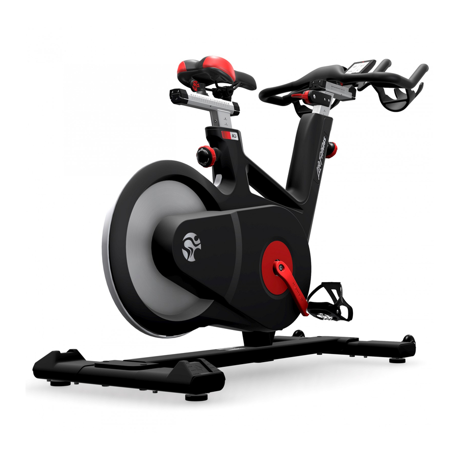
IC5
MODEL NO:IC-LFIC5B2-01
CAUTION!
READ ALL PRECAUTIONS AND INSTRUCTIONS IN THIS MANUAL BEFORE YOU START
USING THIS EQUIPMENT. PLEASE KEEP THIS MANUAL FOR FUTURE REFERENCE.
IMPROPER ASSEMBLY, USE OR MAINTENANCE CAN VOID THE WARRANTY TERMS.
ADDITIONAL LANGUAGES AVAILABLE FOR DOWNLOAD AT WWW.INDOORCYCLING.COM
Version 1.0 2017 IC-LFIC5B2-01 Copyright by Indoor Cycling Group GmbH 2017 | www.indoorcycling.com
MANUFACTURED BY:
Indoor Cycling Group GmbH
Happurger Str. 86
90482 NUERNBERG | Germany
info@indoorcycling.com
www.indoorcycling.com
Phone: +49(0)911 / 54 44 50
Advertisement
Table of Contents

Related Manuals for Life Fitness IC5


Summary of Contents for Life Fitness IC5
- Page 1 MANUFACTURED BY: Indoor Cycling Group GmbH Happurger Str. 86 90482 NUERNBERG | Germany info@indoorcycling.com www.indoorcycling.com Phone: +49(0)911 / 54 44 50 MODEL NO:IC-LFIC5B2-01 CAUTION! READ ALL PRECAUTIONS AND INSTRUCTIONS IN THIS MANUAL BEFORE YOU START USING THIS EQUIPMENT. PLEASE KEEP THIS MANUAL FOR FUTURE REFERENCE. IMPROPER ASSEMBLY, USE OR MAINTENANCE CAN VOID THE WARRANTY TERMS.
- Page 2 ATTENTION During the assembly process, the warning labels on the bikes must be replaced by warning labels in the native language of the country in which the indoor cycle is being used. Version 1.0 2017 IC-LFIC5B2-01 Copyright by Indoor Cycling Group GmbH 2017 | www.indoorcycling.com...
- Page 3 Um das Handbuch in Ihrer Sprache Du kan laste ned bruksanvisningen herunterzuladen, besuchen Sie bitte på ditt eget språk ved å gå til IC5 den IC5 Support Bereich auf unserer støttesiden på: www.teamicg.com Webseite unter www.teamicg.com Pour télécharger le manuel d‘utilisation Du kan hämta bruksanvisningen på...
-
Page 4: Table Of Contents
WARRANTY P.29 TECHNICAL SPECIFICATIONS: The LIFE FITNESS IC5 Bike is, according to EN ISO 20957 (1 & 10), a Class S product for use in a controlled environment such as sports or fitness facilities under the supervision of a trainer. -
Page 5: Important Precautions
IMPORTANT PRECAUTIONS 8. Children under the age of 14 shall only be allowed WARNING! to use the indoor cycle with parental approval and To reduce the risk of serious injury due to improper supervision of a qualified Trainer or Instructor. Use of use of the equipment, carefully read and adhere the bike by persons over the age of 14 only after they to the following important precautions and... -
Page 6: Getting Started
WARNING! You will find the production code for the Life Fitness IC5 Bike on the tag plate which is located on top of the lateral frame tube of the Indoor Bike. Please enter this production code into care and maintenance lists. -
Page 7: How To Assemble The Indoor Cycle
HOW TO ASSEMBLE THE INDOOR CYCLE TORQUE WRENCH 17MM PEOPLE WARNING! Avoid high fluctuations in temperature whilst transporting the bike from the store to the installation site. If there are nevertheless large fluctuations in temperature, please allow the bike to acclimatize to the surrounding temperature before proceeding with assembly. - Page 8 HOW TO ASSEMBLE THE INDOOR CYCLE DANGER OF INJURY! DO NOT REMOVE THE SAFETY PIN BEFORE THE HANDLEBAR HAS BEEN MOUNTED ON THE UPPER HORIZONTAL HANDLE BAR SLIDER! THE VERTICAL HANDLEBAR STEM OF THE INDOOR CYCLE IS SPRING LOADED AND WILL EXTEND QUICKLY UNLESS THE HANDLEBAR IS MOUNTED ONTO THE SLIDER.
- Page 9 HOW TO ASSEMBLE THE INDOOR CYCLE TORQUE WRENCH 6 MM BALL HEX SOCKET 3 MM PEOPLE 30 NM MOUNT THE HANDLEBAR TO THE STEM WITH 2 COUNTER SUNK HEX BOLTS. TIGHTEN TO 30 NM WITH A TORQUE WRENCH. THE BOLTS ARE PRE-COATED WITH A THREAD LOCK WHEN TIGHTENED FOR THE FIRST TIME.
- Page 10 HOW TO ASSEMBLE THE INDOOR CYCLE 2.5 & 6 MM PEOPLE LIFT THE HANDLEBAR TO POSITION 6 AND LOOSEN THE SAFETY PIN AND REMOVE SCREW THE POP PIN KNOB COMPLETELY INTO IT USING A 6 MM HEX KEY. THE FRAME TO LOCK THE HANDLEBAR STEM. 2.5 MM MOUNT THE BRAKE LEVER CAREFULLY SLIDE THE CABLE THROUGH THE OPENING...
- Page 11 HOW TO ASSEMBLE THE INDOOR CYCLE 2.5 & 3 MM PEOPLE 3 MM FASTEN THE BRACKET WITH TWO REMOVE THE BACKING FROM THE ADHESIVE ON BOLTS WITH 3 MM HEX KEY. BOTH SIDES OF THE BRACKET 2.5 MM POSITION THE CABLE AND CONNECTOR INTO THE POSITION THE BRACKET COVER ON THE CONTOUR OF THE BRACKET SO THE CONNECTOR IS BRACKET AND FASTEN WITH COUNTERSUNK...
- Page 12 HOW TO ASSEMBLE THE INDOOR CYCLE 3 MM PEOPLE SLIDE THE SPACER BETWEEN THE SLIDE THE BIKE COMPUTER ONTO BRACKET AND HANDLEBAR. THE COMPUTER BRACKET. The computer user manual is enclosed separately and contains information for setup and operation. 3 MM FASTEN THE BIKE COMPUTER INTO PLACE FROM THE UNDERSIDE OF THE HANDLEBARS WITH ONE BOLT.
- Page 13 HOW TO ASSEMBLE THE INDOOR CYCLE 15 MM PEDAL HAND TIGHT PEOPLE WRENCH WARNING! Attach the pedal marked R on the right crank and tighten by turning clockwise (standard right-hand thread). Attach the pedal marked L on the left crank and tighten by turning counter-clockwise (left-hand thread).
-
Page 14: Installation And Setup
Instructions stated in this manual must be performed during initial installation of the LIFE FITNESS Indoor Cycle in order to ensure optimal performance and a long lifespan. Please read and follow the following instructions carefully. If the Indoor Cycles are not installed and configured as described, the components may be subjected to excessive wear and tear and the bike may become damaged. -
Page 15: Installation And Disposal Of Batteries
INSTALLATION AND DISPOSING OF BATTERIES YOUR LIFE FITNESS IC5 REQUIRES TWO D SIZE BATTERIES BATTERIES MAY NOT: • Come into contact with fire • Come into contact with coins or other metallic objects Products or batteries labelled with this symbol may not be disposed of along with normal household refuse. -
Page 16: How To Adjust The Indoor Cycle
HOW TO ADJUST THE INDOOR CYCLE The Life Fitness Indoor Cycle can be very easily adjusted, depending on the requirements of various user groups. This enables maximum riding comfort to be ensured whilst achieving optimal training results. The configurations described in the following paragraphs demonstrate just a few of the most often used adjustment variations of which the Indoor Cycle is capable. - Page 17 HOW TO ADJUST THE INDOOR CYCLE ADJUSTING THE SADDLE HORIZONTALLY: Properly positioning the saddle horizontally is very important in order to avoid injury to the knees. Sit on the saddle and move the pedals until the crank arms are in the horizontal position. The knee of your forward-facing leg should be positioned directly above the center of the pedal.
- Page 18 HOW TO ADJUST THE INDOOR CYCLE HANDLEBAR POSITIONING: Begin with the top of the handlebars at approximately the same height as the saddle (dotted horizontal line A in the drawing below) for inexperienced users set to the “0“ marking (see dotted vertical line B in the drawing below).
-
Page 19: How To Operate The Indoor Cycle
HOW TO OPERATE THE INDOOR CYCLE RESISTANCE ADJUSTMENT: The resistance adjustment can be set precisely and regulated in fine increments according to the requirements of the cyclist by moving the resistance/emergency lever up or down. The adjustment lever has 110° range of motion . When the lever is up, the resistance is 0% and when it is in the down position, 100%. - Page 20 HOW TO OPERATE THE INDOOR CYCLE EMERGENCY BRAKE (PUSH RESISTANCE ADJUSTMENT LEVER DOWN) RESISTANCE ADJUSTMENT LEVER For safety reasons, please always make sure you pedal in a controlled manner and adjust your pedalling frequency to your own cycling capabilities. MOVING THE INDOOR CYCLE: It is recommended that two people move the Indoor Cycle.
- Page 21 HOW TO OPERATE THE INDOOR CYCLE Check the stability of the Indoor Cycle where it is to be operated and if necessary adjust the levelling feet underneath the front or rear stabilizers to ensure the desired stability. IMPORTANT! Please do not unscrew the levelling feet more than 10 mm! The free standing Indoor cycle shall only be installed and operated on a stable and leveled floor.
-
Page 22: Preventive Maintenance
PREVENTATIVE MAINTENANCE WARNING! Please carefully observe the following instructions. The maintenance and care procedures must be performed in the regularity set out, to ensure maximum operating safety and lifespan. Irregularly observed maintenance and care procedures will lead to increased wear to the product and will void the warranty. - Page 23 PREVENTATIVE MAINTENANCE BI-WEEKLY MAINTENANCE: 1. Emergency brake: To ensure operating safety, the emergency brake must be regularly checked to make sure it is functioning properly. To do this, completely press down the resistance/brake lever whilst pedalling. When functioning optimally, it should produce an immediate braking effect and bring the flywheel to a complete standstill.
- Page 24 PREVENTATIVE MAINTENANCE 3. Handlebars: To maintain the easy adjustment of the handlebar posts, the vertical and horizontal handlebar posts must be regularly cleaned and lubricated. To do this, position the handlebars (A) in the uppermost position, spray the handlebar posts with maintenance spray and rub down the entire exterior surfaces including the horizontal post with a soft cloth.
- Page 25 PREVENTATIVE MAINTENANCE 2. Vertical adjusting of the handlebar and saddle: To ensure the easy adjustment of the vertical handlebar and saddle posts, the thread on the pop-pin-knob must be lubricated. We recommend lithium grease.
-
Page 26: Maintenance Schedule
MAINTENANCE SCHEDULE AND CHECKLIST ACTIVITY ROTATION DETAILS FEET LEVELLING, DISINFECTION & CLEANING OF THE BIKE DAILY P 21-22 DETAILED CLEANING OF THE ENTIRE BIKE WEEKLY P 22 CHECK EMERGENCY BRAKE FUNCTION BI-WEEKLY P 23 CLEAN AND LUBRICATE SADDLE & HANDLEBAR SLIDERS / STEMS BI-WEEKLY P 23-24 CHECK ALL CONNECTIONS AND FIXINGS... - Page 27 MAINTENANCE SCHEDULE AND CHECKLIST BI-WEEKLY MAINTENANCE CHECKLIST BIKE NO. PRODUCTION CODE OBSERVATIONS ACTION TAKEN RESULT NAME / DATE MONTHLY MAINTENANCE CHECKLIST BIKE NO. PRODUCTION CODE OBSERVATIONS ACTION TAKEN RESULT NAME / DATE...
-
Page 28: Spare Parts
For further information please contact your local distributor or visit www.indoorcycling.com. 120-01-00015-02 SPORT SADDLE BLACK & RED INCL. SADDLE CLAMP 320-00-00010-01 WATTRATE LCD COMPUTER INCLUDING ® FASTENING MATERIAL FOR IC5 900-10-00003-01 LEVELING FEET, RUBBER 75° SHORE 150-01-00005-03 COMBI PEDAL SET, SPD COMPATIBLE 150-03-00048-01 TOE STRAP SET... -
Page 29: Warranty
WARRANTY ICG warrants that all new equipment will be free of manufacturing defects in workmanship and materials, effective on the date of original assembly at its production facility. Parts repaired or replaced under the terms of this warranty will be warranted for the remainder of the original warranty period only. ICG is obligated to uphold its manufacturer warranty obligation so long as the product is used in the closed environment it was designed for, Temperature range between 15ºC~40°C Celsius (59ºF~104°F) and max. - Page 30 Version 1.0 2017 IC-LFIC5B2-01 Copyright by Indoor Cycling Group GmbH 2017 | www.indoorcycling.com...
- Page 32 CAUTION. READ ALL PRECAUTIONS AND INSTRUCTIONS IN THIS MANUAL BEFORE YOU BEGIN USING THIS EQUIPMENT. PLEASE KEEP THIS MANUAL FOR FUTURE REFERENCE. IMPROPER ASSEMBLY, SET UP, USE OR MAINTENANCE MAY VOID THE WARRANTY. EMAIL: INFO@INDOORCYCLING.COM WEBSITE: WWW.INDOORCYCLING.COM © 2017 Indoor Cycling Group Manufactured by: Indoor Cycling Group®...
Need help?
Do you have a question about the IC5 and is the answer not in the manual?
Questions and answers
How do you operate the monitor (time, distance calorie count, etc?
To operate the monitor on the Life Fitness IC5 for time, distance, and calorie count, you can start by pressing the quick start button. The WattRate LCD computer will display metrics such as RPM, watts, calories, miles, and miles per hour. You can adjust the screen settings or turn the screen on or off. The monitor provides real-time data for tracking your workout progress.
This answer is automatically generated