Sign In
Upload
Manuals
Brands
Giga-tronics Manuals
Measuring Instruments
8003
Giga-tronics 8003 Manuals
Manuals and User Guides for Giga-tronics 8003. We have
1
Giga-tronics 8003 manual available for free PDF download: Operation Manual
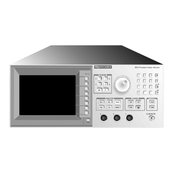
Giga-tronics 8003 Operation Manual (258 pages)
precision scalar analyzer
Brand:
Giga-tronics
| Category:
Measuring Instruments
| Size: 3 MB
Table of Contents
Table of Contents
5
About this Manual
13
Conventions
15
Record of Manual Changes
17
Special Configurations
19
Introduction
21
Description
21
Features
21
Installation
22
Safety Precautions
22
Figure 1-1: Power Line Connection
22
Power Input, Fuse & Voltage Selector
23
Line Voltage & Fuse Selection
23
Power Sensors
23
Power Sensors Accessories
23
Power Sensor Precautions
23
Power Requirements
24
Figure 1-2: Operating Voltage Selection
24
Standard Voltage Selector & Fuse Holder
25
VDE Type Voltage Selector & Fuse Holder
25
Environmental Requirements
25
Items Furnished
25
Items Required
26
Tools & Test Equipment
26
Cooling
26
Cleaning
26
Receiving Inspection
26
Preparation for Reshipment
26
Specifications
27
Cursors & Markers
28
Accuracy
29
Figure 1-3: Uncertainty Due to Instrument Linearity & Zero Set Vs. Input Power
29
Transmission Loss or Gain Measurements
29
Figure 1-4: Reflection Uncertainty Relative to Directivity
30
Figure 1-5: Reflection Uncertainty Relative to Source Match
30
Reflection Measurements
30
Absolute Power Measurement Accuracy
31
GPIB Interface
33
Rear Panel Inputs & Outputs
34
BNC Connectors
34
GPIB Connectors
34
Signal Sources
35
System Integrated
35
Operator Integrated
35
Modulation
35
General Specifications
35
Introduction
37
Front & Rear Panel Descriptions
37
Figure 2-1: 8003 Front & Rear Panel Components
38
GPIB Address Selection
43
Display Description
44
Figure 2-2: Display Screen Information Locations
44
Figure 2-3: Typical Channel Summary Indications
46
Softkey Functional Description
48
Softkey Labels & Color Indications
48
Channel & Function Selection
48
Sensors & Sensor Calibration
48
Figure 2-4: 8003 Front Panel Controls
48
Absolute Power & Swept Capabilities
49
Graph & Readout Display Modes
49
Path Calibration Memory
49
Trace Memory
50
Power on
50
CHANNEL Controls
51
OFF Key
51
DEFINE Key
51
Figure 2-5: Channel Control Menus Access W/ DEFINE Key
53
FUNCTION Controls
54
MEAS Key
54
Figure 2-6: Function Menus Accessed with the MEAS & SCALE Keys
54
SCALE Key
58
DISPLAY Key
60
Figure 2-7: Function Menus Accessed W/ DISPLAY Key
62
Figure 2-8: PLOT ALL Function Hardcopy Printout (Typical)
63
Figure 2-9: PLOT 4 Function Hardcopy Printout
64
Figure 2-10: SC P1P2 Function Screen Hardcopy Printout
65
CAL Key
72
Figure 2-11: Function Menus Accessed with the CAL Key
72
CURSOR Key
76
Figure 2-12: Function Menus Accessed with the CURSOR & MEMORY Keys
78
MEMORY Key
83
SOURCE Controls
87
General Description
87
ATE Operation
87
8003 Source Compatibility
87
Key Operation
88
Figure 2-13: Softkey Menu Change from Frequency Change Prompt
88
START Key
88
UPDATE SWEEPER ON/OFF Key
88
Figure 2-14: Stop Key Softkey Menu Prompt
89
STOP Key
89
POWER Key
90
Figure 2-15: Power Softkey Menu Prompt
90
SWEEP TIME Key
92
SYSTEM Controls
93
PRESET Key
93
CONFIG Key
93
Figure 2-16: System Control Menus Accessed with CONFIG Key (Part 1)
94
Figure 2-17: System Control Menus Accessed with the CONFIG Key (Part 2)
95
Front Panel Operation
102
Figure 2-18: Analyzer, Sweeper, Sensor & Bridge Interconnection
102
Calibrating for Power Measurement
103
Figure 2-19: CAL Softkey Menu
103
Figure 2-20: Sensor CAL Menu
103
Calibration Intervals
104
Figure 2-21: Sensor Calibration Display Screen
104
Path Calibration Correction for Component Variations
105
Figure 2-22: New Frequency Parameters Display Screen
105
Set up Sweep Parameters
105
Figure 2-23: Autoscaled Thru Path before Path Calibration Display
106
Frequency Response Correction
106
Figure 2-24: THRU PATH Calibration Menu
107
Figure 2-25: Calibrated Path Display
108
Figure 2-26: Successful SHORT/OPEN CAL Display W/ Open Attached
109
Making a Device Measurement
109
Figure 2-27: Device Measurement Plot (Typical Display)
110
Figure 2-28: Cursor Plot Typical Display
110
Insertion & Return Loss Measurements
111
Single-Sensor Insertion Loss Measurement
111
Figure 2-29: Swept Source & Power Sensor Only Block Diagram (W/ DUT)
111
Figure 2-30: more Accurate Insertion Loss Ratioing Meas
112
Using Channels
112
Two-Sensor Insertion Loss Measurements
113
Figure 2-31: Two Sensor Insertion Loss Setup W/ a Power Splitter
113
Figure 2-32: Two Sensor Insertion Loss Using a Directional Coupler
113
Single-Sensor Return Loss Measurements
115
Figure 2-33: Return Loss Setup Using a Bridge
115
Figure 2-34: Return Loss Test Setup Using a Directional Coupler
116
Two-Sensor Return Loss Measurements
117
Figure 2-35: Two Sensor Return Loss Setup Block Diagram
117
Three-Sensor Configurations
118
Trace Memory
118
Figure 2-36: Three Sensor Configuration Block Diagram
118
Figure 2-37: "Golden Standard" Precision 20 Db Attenuator Measurement Using 20 Db
119
Scaling the Display
120
Figure 2-38: Device Gross Characteristics (Filter Skirt) Display
120
Figure 2-39: Device Fine Characteristics (Filter Pass Band) Display
120
Figure 2-40: SCALE Display & Softkey Menu Typical Display
121
Hints on Simplified Scaling
122
Using the Cursor to Set the Reference Level
122
Cursors & Markers
123
Figure 2-42: Typical Measurement (Cursors, Delta Cursors & Markers)
123
Min & Max Search
123
Search Functions Using the Cursor
123
Figure 2-43: MAX Search Finds Minimum Return Loss of a Filter (Passband)
124
Figure 2-45: -3 Db Point (Low Pass Filter) at 3.175 Ghz
125
Searches on Frequency Selective Devices
125
Figure 2-46: -30 Db Point (High Pass Filter)
126
Bandwidth Searches
127
Figure 2-47: Automatic Bandwidth Movement (very Narrow Bandpass Filter)
127
Cursor Delta (∆) Functions
128
Figure 2-48: Cursor Delta Indicates Relative Level & Frequency (Next Worse Return Loss Point)
128
Cursors on Multiple Channels
129
Figure 2-49: Cursors (each Channel) Tied to same Frequency Help Finding the 1 Db Compression Point on an Amplifier
129
Figure 2-50: Filter Passband (Tuned until Amplitude Is -0.5 Db at the Marker)
130
Markers
130
Power Measurements
131
Figure 2-51: Sensor Calibration Screen
131
Figure 2-52: Sensor ID Table
132
Figure 2-53: Sensor CAL Factor Table
132
Figure 2-54: 8003 Swept Power Measurements with CAL Factor Correction
133
CW Power Measurements
134
Figure 2-55: CW Readings (All 3 Sensor Inputs Plus Ratio)
134
Mixed Mode Measurements
134
Cal Factor Corrections in the CW Mode
135
Figure 2-56: 3 Different Methods (CAL Factor Correction Plus Sensor Offsets)
135
Figure 2-57: Averaging Used to Reduce Noise
136
Other CW Functions
136
Sensor Offsets
136
Figure 2-58: Reference Level & Corresponding Relative Reading
137
Accurate Range Measurements
138
CW Mode
138
Measurement Modes
138
Temperature Stability
138
Swept Mode with AC Detection
139
Swept Mode with DC Detection
139
8003 Power Sweep Measurements
140
Figure 2-59: Menus & Typical Display (Power Sweep Measurements)
140
Remote Operation
143
Introduction
143
IEEE Bus Interface
143
Connect the System Controller
143
Set the GPIB Address
143
Figure 3-1: Location of Gpib/System Connection (Rear Panel)
143
Programming the 8003
144
Structured GPIB Language
149
Common Structure
149
8003 GPIB Commands
149
Figure 3-2: GPIB Commands (Front)
150
Measurement Commands
150
Figure 3-3: GPIB Commands (Back)
151
Calibration Commands
151
Command Execution
152
Case Insensitivity
152
Ds Definition
152
EOL Definition
152
Hs Definition
152
Us Definition
152
IEEE GPIB Interface Characteristics
153
Channel Bias Voltage Definition Command Structure
154
Sensor Calibration Command Structure
154
Channel Definition Command Structure
155
Cursor Definition Command Structure
156
Instrument Preset Command Structure
160
Disable Private Bus Command Structure
161
Enable Private Bus Command Structure
161
External Status Register Query Command Structure
162
Fixed Frequency Source Mode Definition Command Structure
163
Graph Display Definition Command Structure
165
Instrument Identifier Command Structure
165
Input Command Structure
166
Key Stroke Emulation Enable/Disable Command Structure
167
Table 3-1: Definition of ASCII Codes
168
Figure 3-4: Plot Obtained Using more Complex HP Series 300 Prg. Example
170
Memory Command Structure
171
Measurement Query Command Structure
172
Plot Command Structure
175
CW Power Measurement Command Structure
178
Temperature & Low Level Offset Update Structure
191
Print Definition Command Structure
191
Readout Display Definition Command Structure
192
Sensor Definition Command Structure
193
Sensor Short/Open Calibration Command Structure
195
Swept Measurement Command Structure
196
Figure 3-5: Limit Line Display Example
205
Start/Stop Swept Frequency Source Mode Def. CMD. Structure
206
Span Swept Frequency Source Mode Def. CMD. Structure
209
Sensor Path Calibration Command Structure
211
Sensor Zeroing Command Structure
212
Status Messages
212
488.2 Status Byte
212
External Status
213
GPIB/PRIVATE Interface
213
Pass through Feature
214
Performance Test & Calibration
215
General
215
Table 4-1: Test Equipment Required
216
Calibrator Verification Procedure
217
Calibrator Output Power Reference Level
217
Figure 4-1: Calibrator Output Test Setup
217
Procedure
217
Calibrator Frequency Check
219
Performance Verification Tests
220
Equipment Required
220
Instrument Plus Power Sensor Linearity
221
Figure 4-2: Power Linearity Test Setup
221
Test Description
221
Setup Parameters
222
Test Procedure
222
Serial Port Check
224
Gpib/System Port Check
224
Gpib/Private Port Check
225
Sweep in Connector Check
225
AC Mode Output Connector Check
226
Bias Output Connector Check
226
DAC Output Connector Check
227
RGB Video Output Connector Check
227
Summary
227
Power Sensors
233
Introduction
233
Power Sensor Selection
233
A.1 Introduction
233
Power Sensor Selection Charts
234
Table A-1: Power Sensor Selection Guide
234
Table A-2: Power Sensor Cal Uncertainties
235
Directional Bridges
236
Table A-3: Directional Bridge Selection Guide
236
A.2.2 Directional Bridges
236
System Configuration
237
Introduction
237
8003 Default Parameters
237
Table B-1: 8003 Default Settings
237
B.1 Introduction
237
Manual 20791, Rev. C, June
238
8003 System
239
B.3 8003 System
239
Bridge Installation
239
Sensor Installation
239
8003 To Sweeper BNC Connections
240
B.3.3 Sweeper Installation
240
Sweeper Installation
240
GPIB Interconnect Cable Connections
241
Printer Installation
242
B.4 Printer Installation
242
Paintjet Color GPIB Cable Interconnections
243
Thinkjet GPIB Cable Interconnections
243
Laserjet Family RS-232 Cable Interconnections
244
RS-232 Electrical Description
244
Laserjet Printer Switch & Jumper Location and Settings
245
Plotter GPIB Installation Interconnections & Pen Colors
246
Hp 7550A
246
HP 7550A Pen Color Format (8 Pens
246
B.5.2 Hp 7440A
247
Hp 7440A
247
HP 7440A Pen Color Format (8 Pens
247
B.5.3 Hp 7475A
248
Hp 7475A
248
HP 7475A Pen Color Format (6 Pens
248
B.5.4 Hp 7470A
249
Hp 7470A
249
HP 7470A Pen Color Format (2 Pens
249
B.5.5 Hp 7090A
250
Hp 7090A
250
HP 7090A Pen Color Format (6 Pens
250
Connecting Analyzer to an Instrument Controller
251
Precision Scalar Analyzer Index
253
Definition of ASCII Codes
254
Advertisement
Advertisement
Related Products
Giga-tronics 8501A
Giga-tronics 8502A
Giga-tronics 8650A Series
Giga-tronics 8650B Series
Giga-tronics 80350A
Giga-tronics 80353A
Giga-tronics 80354A
Giga-tronics 80355A
Giga-tronics 80351A
Giga-tronics 80352A
Giga-tronics Categories
Multiplexer
Amplifier
Switch
Measuring Instruments
Synthesizer
More Giga-tronics Manuals
Login
Sign In
OR
Sign in with Facebook
Sign in with Google
Upload manual
Upload from disk
Upload from URL