Table of Contents
Advertisement
Advertisement
Table of Contents

Related Manuals for Rockville Phenom RXH-F5


Summary of Contents for Rockville Phenom RXH-F5
- Page 1 OWNERS MANUAL...
- Page 2 Our competition is satisfied with just continuing to build the same units year after year without thought for improvement, but not Rockville. We consider it our mission to use our expertise in developing the latest technologies and to bring you the absolute best sounding amplifiers on the market and of course at a reasonable price.
- Page 3 (You can only imagine what they sound like.) Rockville uses only true audio transistors in the audio To reset the amplifier, you must first diagnose what caused the problem, correct the fault section of these amplifiers.
-
Page 4: Battery Voltage
BATTERY VOLTAGE: Rockville RX Phenom Series amplifiers are rated and regulated to 13.8 volts and below. Increasing DC Offset Protection: Should any DC voltage try to enter the amplifier via the speaker voltage to 14.4 volts will increase the power output of the amplifier in the same proportion. Maximum terminals it will cause the amplifier to shut down and not operate until this condition is input voltage is 14.4 volts while the minimum voltage is 12 volts. - Page 5 Installation Basics The remote turn on connection is located on the barrier strip next to the power and ground SETTING THE CONTROLS: connections. This connection is responsible for turning the amplifier on and off with the rest of the system. A smaller gauge wire can be used to make this connection to your radio’s power AUDIO PREAMP INPUT antenna lead.
- Page 6 Installation Basics ADJUSTING THE SYSTEM USING THE ELECTRONIC CROSSOVER - 4 CHANNEL MODELS The four and five channel models feature separate crossovers for channels 1-2, 3-4, Once the system is operational, the first thing to do, is set all crossover points to approximate and 5.
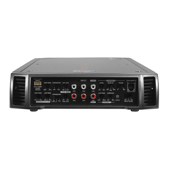
- Page 8 Special Features HIGH LEVEL INPUTS Many factory radios do not have pre-amp outputs thus these Phenom amp models feature High Level inputs: RXA-F1, RXA-F2, RXA-T1, and RXH-F5. High Level inputs, also referred to as Speaker Level inputs, allow you to connect to the factory speaker wires.
- Page 9 CLONE FUNCTION The Phenom RXA-F1 and RXA-F2 feature a unique CLONE FUNCTION to assist in setting up a 2-channel bridged system with perfect gain and crossover tracking between the speakers. Typically when setting up a system you would need to set up channels 1 - 2 and then channels 3 - 4 crossovers and gains separately not guaranteeing perfect balance or frequency cutoffs.
- Page 10 4 Channel Amp with 2 C hannel Input If your head unit has only one pair of Left and Right RCA out put jacks, plug them in to RCA input Jacks 1 and 2 of the amplifier and set the Input model switch to the 2CH position.
- Page 11 4 Channel Amp with 4 C hannel Input If your head unit has 2 pairs of RCA output jacks, input Front Left and Front Right in to Channels 1 and 2. Then attach radio output Rear Left and Rear Right to Channels 3 and 4. Set the Input Mode Switch to 4Ch position.
- Page 12 Basic 4 Channel Configuration CROSSOVER MODE SWITCHES IN FULL RANGE POSITION INPUT CROSSOVER HIGH LEVEL FREQUENCY INPUT MODE CLONE CH3 & CH4 MULTIPLIER INPUT LEFT LPF / BPF FULL FULL STATUS + - GND + - + - GND + - X-OVER AUTO START SMART...
- Page 13 4 Channel Amplifier Bridged to 2 Channels CHANNEL 1-2 CROSSOVER CHANNEL 3-4 CROSSOVER SWITCH TO CLONE SWITCH TO LPF/BPF INPUT CROSSOVER HIGH LEVEL FREQUENCY INPUT MODE CLONE CH3 & CH4 MULTIPLIER INPUT LEFT LPF / BPF FULL FULL STATUS + - GND + - + - GND + - X-OVER AUTO START...
- Page 14 4 Channel Amplifier in 3 Channel Mode CROSSOVER MODE SWITCH IN FULL CROSSOVER MODE SWITCH RANGE OR HIGH PASS POSITION IN LOW PASS POSITION Channels 1 and 2 should be wired to speakers no lower INPUT CROSSOVER HIGH LEVEL FREQUENCY INPUT MODE CLONE CH3 &...
- Page 15 4 Channel with Mixed Mono CROSSOVER MODE SWITCH CROSSOVER MODE SWITCH IN HIGH PASS POSITION IN LOW PASS POSITION INPUT HIGH LEVEL CROSSOVER FREQUENCY INPUT MODE CLONE CH3 & CH4 MULTIPLIER INPUT LEFT LPF / BPF SUBWOOFER FULL FULL STATUS MINIMUM IMPEDANCE + - GND + - 8 OHMS...
- Page 16 4 Channel with Dual Mixed Mono Configuration SYSTEM A SUBWOOFER MINIMUM IMPEDANCE 4-8 OHMS FRONT SPEAKERS ALL CROSSOVER SETTINGS IN THIS MODE LOW PASS SHOULD BE SET TO FULL RANGE. FILTER INDUCTOR RIGHT LEFT SPEAKER SPEAKER 4 OHM 4 OHM FUSE +12V MINIMUM...
- Page 17 RXH F5 Channel Input Mode If your head unit has one single pair of RCA outputs, input them in to the amplifiers Channel 1 and 2 input jacks and set the Input Mode 2 CHANNEL MODE Switch to 2Ch. The amplifiers preamp circuitry will automatically mix all the channels and output will occur on all 5 channels.
- Page 18 5 Channel Amplifier Speaker Wiring COMPONENT SPEAKERS MINIMUM IMPEDANCE 2-4 OHMS Minimum impedance for channels 1 through 4 is 2 ohm stereo. Channel five minimum impedance is 2 ohm mono capable. SUBWOOFER MINIMUM IMPEDANCE COMPONENT 2-4 OHMS SPEAKERS MINIMUM IMPEDANCE 2-4 OHMS INPUT MODE SET TO 5 CHANNEL...
- Page 19 Class D Mono Block 1 Ohm Amplifier 2 OHM MINIMUM LOAD The RXDM2 model is a 1 ohm mono block amplifier. - OR - No matter how many woofers you choose to wire up to 2 OHM SUBWOOFER 2 OHM SUBWOOFER the final impedance should not fall below this model, 1 ohm.
- Page 20 Class D Mono Block 1 Ohm Amplifier RXDM1 is a 1 ohm stable mono block amplifier. It features RCA pre amp line outputs for feeding of a full range signal to a secondary full range amplifier in a multi-amp system.
- Page 21 Class D Mono Block 1 Ohm Amplifier 1 OHM MINIMUM LOAD - OR - The RDXM1 is a 1 ohm mono block Class D amplifier. No matter the final how many woofers you choose to wire up to this amplifier, 2 OHM SUBWOOFER 2 OHM SUBWOOFER impedance load should not fall below 1 ohm.
- Page 22 Twin Amplifier Bridging SWITCH SET TO MASTER You can only bridge 2 of the same amplifiers together. DO NOT bridge different models together. MASTER REMOTE SUBWOOFER LEVEL CONTROL SWITCH SET TO SLAVE MASTER / SLAVE LINK SLAVE...
- Page 23 Make sure to use the supplied DATA CABLE for linking of the amplifiers and not the dash board bass remote cable or any other phone jack cable. If you misplace your cable, contact Rockville or your local dealer to procure a new one.
- Page 24 Twin Amplifier Bridging IMPORTANT NOTE: SUBWOOFER MINIMUM CONNECT THE TWO SPEAKER NEGATIVES IMPEDANCE 2 OHMS TOGETHER WITH A # 12 WIRE STRAP.
- Page 25 Twin Amplifier Bridging Once again, when bridging two amplifiers together, the final impedance load of the bridged amplifiers should be no lower than 2-ohms. Double power will occur at 2-ohms. Master amplifiers positive (+) speaker terminal should be wired to the positive terminal of the subwoofer. Slave amplifiers positive (+) speaker terminal should be wired to negative terminal of the subwoofer.
- Page 26 Specifications RXH-F5 RXA-F2 5 Channel Amplifier Channels 1 - 4 • CEA Power Rating: 400 Watts (4 x 100 Watts) at 4 Ohms and 1% THD+N • CEA Power Rating: 200 Watts (4 x 50 Watts) at 4 ohms and 1% THD+N •...
- Page 27 Specifications RXA-F1 RXA-T1 • CEA Power Ratings: 260 Watts (4 x 65 Watts) at 4 ohms and 1% THD+N • CEA Power Rating: 250 Watts RMS (2 x 125 Watts) at 4 Ohms and 1% THD+N • RMS: 500 Watts (4 x 125 Watts) at 4 ohms and 1% THD+N •...
- Page 28 Specifications RXA-T2 RXD-M5 • CEA Power Rating: 400 Watts (2 x 200 Watts) @ 4 ohm and 1% THD+N • CEA Power Rating: 1 x 2000 Watts @ 1 ohm and 1% THD+N • RMS: 1200 Watts (2 x 600 Watts) @ 2 ohm •...
- Page 29 Specifications RXD-M4 RXD-M3 • CEA Power Rating: 1 x 1500 Watts @ 1 ohm and 1% THD+N • CEA Power Rating: 1 x 1000 Watts @ 1 ohm and 1% THD+N • RMS: 1 x 3000 Watts @ 1 ohm and 1% THD+N •...
- Page 30 RXD-M2 RXD-M1 • CEA Power Rating: 1 x 750 Watts @ 1 ohm and 1% THD+N • CEA Power Rating: 1 x 500 Watts @ 1 ohm and 1% THD+N • RMS: 1 x 1000 Watts @ 1 ohm and 1% THD+N •...
- Page 31 RXD-M0 • CEA Power Rating: 1 x 300 Watts @ 1 ohm and 1% THD+N • RMS: 1 x 600 Watts @ 1 ohm and 1% THD+N • Peak Power: 1 x 1200 Watts @ 1 ohm • Minimum THD at Rated Power: < 0.05% •...
- Page 32 Speaker Wiring Chart 4 + 4 4 + 4 4 + 4 4 + 4 4 + 4 4 X DUAL VC 8 OHM 2 OHM SPEAKERS WITH AMPLIFIER VOICE COILS, ALL IN PARALLEL SERIES: PARALLEL: 4 OHM TO 2 OHM TO SINGLE VOICE SINGLE VOICE AMPLIFIER...
- Page 33 Speaker Wiring Chart SERIES: PARALLEL: DUAL VOICE COIL DUAL VOICE COIL SPEAKERS SPEAKERS Please note that the minimum impedance load for single RX Phenom Series Amplifiers is 2 ohm stereo and 4 ohm mono bridged. 4 + 4 8 OHM TO AMPLIFIER Lower impedance loads will cause overheating 4 + 4...
- Page 34 Notes...
- Page 35 Notes...
- Page 36 Features and specifications subject to change and or improvement without notice. Though we tried our best to ensure that this manual is free and clear of errors please don’t hold us responsible for printing errors. Copyright 2015 RockvilleAudio.com...
Need help?
Do you have a question about the Phenom RXH-F5 and is the answer not in the manual?
Questions and answers
What are the high level inputs speakers colors