Table of Contents
Advertisement
Quick Links
Advertisement
Table of Contents

Related Manuals for Agilent Technologies 708-DS


Summary of Contents for Agilent Technologies 708-DS
- Page 1 708-DS Dissolution Apparatus Operator’s Manual Agilent Technologies...
- Page 2 Notices Warranty © Agilent Technologies, Inc. 2016 puter Software or Computer Software Documentation). No part of this manual may be reproduced The material contained in this doc- in any form or by any means (including Safety Notices ument is provided “as is,” and is...
-
Page 3: Table Of Contents
Environmental Requirements for Installation Clearance Equipment, Parts, and Accessories As Shipped Parts and Accessories Tubing / Cable Connections 708-DS Heater / Circulator Setup Instrument Level / Water Bath Setup Level Instrument Bath Temperature Probe Installation Handheld Probe Installation 708-DS Operator’s Manual... -
Page 4: Figure 55. Menu Screen - Instrument Settings Screen
Contents Power Cord Connections 708-DS Initial Power Up Filling the Water Bath Level Instrument - Re-verification Heater / Circulator Power-up Agilent 708-DS Setup Vessel Installation Sample Manifold Installation Accessory Installation Setting Basket (Apparatus 1) Heights Setting Paddle (Apparatus 2) Heights... - Page 5 Contents Menu Screen - Calibration Menu Screen - Diagnostics Menu Screen - User Access General 708-DS Conventions Alphanumeric Data Entry Numeric and Time / Date Entry Parameter Limits / Ranges Agilent 708-DS Notifications Main Screen - Error Conditions Dialog Screens (Green / Blue)
- Page 6 Contents Accessing the Top Cover Removing Top Cover Replacing the Top Cover Printer Maintenance Removing a Thermal Paper Roll Inserting a Thermal Paper Roll (5095-0307) Thermal Printer Test Obtaining Warranty and Other Services 708-DS Operator’s Manual...
-
Page 7: Figures
Figure 22. Main Screen - Display Parameters Figure 23. Sample Temperatures Figure 24. Select Start Type Figure 25. Select Method Figure 26. Start Options Figure 27. Manual Operation Figure 28. Data Entry Figure 29. Main Screen - Stop 708-DS Operator’s Manual... - Page 8 Figure 31. Method Paused Figure 32. Pause Duration Alarm Figure 33. Manual Lift Knob Figure 34. Taking a Manual Sample Figure 35. Agilent 708-DS Standard Evaporation Cover Figure 36. Lock the Instrument Figure 37. Unlock the Instrument Figure 38. Remote Control Figure 39.
- Page 9 Figure 69. Removing the Thermal Paper Roll Figure 70. Inserting a Thermal New Paper Roll Figure 71. Leading Paper and Closing the Lid Figure 72. Closing the Printer Chamber Figure 73. Feeding Paper Figure 74. Printer Test 708-DS Operator’s Manual...
- Page 10 Figures This page was intentionally left blank, except for this message. 708-DS Operator’s Manual...
-
Page 11: Safety
Operator’s Manual Safety Electrical Hazards The Agilent 708-DS has been designed and tested so that when used properly you have an accurate, fast, flexible, and safe instrument. If the equipment is used in a manner not specified by the manufacturer, the protection provided by the equipment may be impaired. -
Page 12: Electrical Hazards
Do not connect the instrument to the main power supply until you have made sure that the operating voltage is correctly set for the main power supply in the specific outlet in your laboratory to which the equipment will be connected. 708-DS Operator’s Manual... -
Page 13: Warning
A ‘Caution’ message appears in the manual when failure to observe instructions could result in damage to equipment (Agilent supplied and / or other associated equipment). Note NOT E A ‘Note’ appears in the manual to give advice or information. 708-DS Operator’s Manual... -
Page 14: Information Symbols
European Standard EN 50419. For more information on collection, reuse, and recycling systems, please contact your local/regional waste administration, your local distributor, or Agilent. Indicates the product complies with regulatory compliance requirements of New Zealand and Australia. 708-DS Operator’s Manual... -
Page 15: Introduction
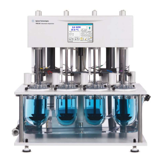
708-DS Dissolution Apparatus Operator’s Manual Introduction Conventions Used in this Manual Serial Number Format Agilent Technologies... - Page 16 Introduction Agilent’s 708-DS Dissolution Apparatus is designed for dissolution testing of a variety of pharmaceutical products, including tablets, capsules, and transdermal patches. Interaction with the instrument is simplified with an intuitive, color touchscreen interface. Temperature control is achieved using traditional water bath vessel heating. This...
-
Page 17: Conventions Used In This Manual
Introduction Conventions Used in this Manual • Items you are asked to press are in bold. For example, “press H on the keypad”. • Key sequences you are asked to press appear like this: MENU > 7. 708-DS Operator’s Manual... -
Page 18: Serial Number Format
Country of origin 2 alpha characters matching the required trade designation for the country of origin Year of manufacture ‘09’ for 2009, ‘10’ for 2010, etc. Week of manufacture ‘01’ for week 1 to ‘52’ for week 52 708-DS Operator’s Manual... -
Page 19: Setting Up The 708-Ds
708-DS Dissolution Apparatus Operator’s Manual Setting Up the 708-DS Initial Setup Equipment, Parts, and Accessories As Shipped Tubing / Cable Connections Instrument Level / Water Bath Setup Agilent 708-DS Setup Agilent Technologies... -
Page 20: Initial Setup
Setting Up the 708-DS Initial Setup Complete the following sections to unpack the Agilent 708-DS and ensure it is set up in an appropriate location. Unpacking Procedure Figure 1 Unpacking 708-DS Operator’s Manual... -
Page 21: Figure 2 Removing The Apparatus
Setting Up the 708-DS 1 Remove the Agilent 708-DS and all other system components from the packing material. Figure 2 Removing the Apparatus 2 Inspect the equipment and accessories to ensure there has been no damage during shipment. 708-DS Operator’s Manual... -
Page 22: Environmental Requirements For Installation
2 Ensure a minimum clearance of 30 cm above the unit (when fully raised) and 10 cm at the rear and on both sides of the Agilent 708-DS. Approximately 82 cm x 82 cm total bench space is required per apparatus. -
Page 23: Equipment, Parts, And Accessories As Shipped
Setting Up the 708-DS Equipment, Parts, and Accessories As Shipped Parts and Accessories Locate the following items, as applicable, for your system configuration: 708-DS Dissolution Apparatus Alignment Posts or Evaporation Plugs Heater / Circulator Evaporation Covers 6-pin Cable for Heater / Circulator... -
Page 24: Tubing / Cable Connections
Setting Up the 708-DS Tubing / Cable Connections Complete the following sections to connect the necessary tubing and cables for the Agilent 708-DS. 708-DS Heater / Circulator Setup Do not turn on the heater / circulator before filling the water bath to CAUTION avoid damaging the internal heating elements of the circulator. -
Page 25: Instrument Level / Water Bath Setup
Setting Up the 708-DS Instrument Level / Water Bath Setup Complete the following sections to properly level the instrument and fill the water bath. Level Instrument Figure 4 Levelers and Stability Feet 708-DS Operator’s Manual... -
Page 26: Figure 5 Level-Adjustment Screw Caps
Setting Up the 708-DS 1 Remove the black caps from the five (5) screws located on the front, side, and rear of the base plate of the dissolution apparatus. Figure 5 Level-Adjustment Screw Caps 2 Raise the side stability feet located toward the back on either side of the base plate so they are not touching the laboratory bench. -
Page 27: Figure 6 Raising The Stability Feet
Setting Up the 708-DS Figure 6 Raising the Stability Feet 3 Using the 90º Allen key in the top of the front level-adjustment screws, adjust the screws to achieve left-to-right level within tolerance. It may be necessary to loosen the nut(s) beneath the base plate to allow for adjustment. -
Page 28: Bath Temperature Probe Installation
Setting Up the 708-DS Bath Temperature Probe Installation 1 Insert the water bath temperature probe into the BATH TEMP jack on the rear of the dissolution apparatus drive unit. Figure 7 BATH TEMP Connector 2 Place the other end of the temperature probe through the hole in the center of the vessel plate in the water bath. -
Page 29: Handheld Probe Installation
Setting Up the 708-DS Handheld Probe Installation 1 If applicable, insert the handheld vessel temperature probe cable into the VESSEL TEMP jack on the rear of the dissolution apparatus drive unit. 2 Place the vessel temperature probe in the hole in the vessel plate, at the left side rear of the apparatus. -
Page 30: Filling The Water Bath
Setting Up the 708-DS Filling the Water Bath 1 If necessary, press and hold Drive on the Main screen to allow for access to the water bath. 2 Fill the water bath to an appropriate level with purified water, using the label affixed to the bath as a guide. -
Page 31: Level Instrument - Re-Verification
Setting Up the 708-DS Level Instrument - Re-verification 1 With the water bath filled, re-verify the instrument level front to back and right to left using a bubble or digital level. Heater / Circulator Power-up Use ultrapure water when possible to minimize scale and mineral NOT E buildup. -
Page 32: Agilent 708-Ds Setup
Setting Up the 708-DS Agilent 708-DS Setup Complete the following sections to set up the Agilent 708-DS. Vessel Installation 1 Press Drive to move the drive unit to the fully raised position. 2 Carefully install the dissolution vessels in the vessel plate. -
Page 33: Figure 10 Positioning The Manifold For Installation
Setting Up the 708-DS 2 Position the sample manifold so the center screw is aligned with the center receptor beneath the drive unit. Ensure the left and right alignment shafts are also positioned correctly. Figure 10 Positioning the Manifold for Installation 3 Push the manifold up into the drive unit until resistance is met. -
Page 34: Figure 11 Connecting Autotemp
Setting Up the 708-DS 5 If the unit is equipped with AutoTemp, attach the two 9-pin RS232 cables to the underside of the drive unit. Figure 11 Connecting AutoTemp 6 If the unit is equipped with autosampling, locate the black sample tubing fasteners and attach the fastener to the sample tubing wrap. -
Page 35: Figure 12 Affixing The Fasteners
Setting Up the 708-DS 7 If applicable, affix the fasteners to the underside of the drive unit. A fastener is affixed to the left and to the right of the center drive unit lift. Figure 12 Affixing the Fasteners 708-DS Operator’s Manual... -
Page 36: Accessory Installation
Setting Up the 708-DS Accessory Installation 1 Locate the appropriate accessories from the following list to be configured with the Agilent 708-DS: evaporation covers, Dosage Delivery Modules (DDMs), alignment posts, receptor shafts, paddle shafts, basket shafts, and shaft locking collars. -
Page 37: Figure 14 Installing Evaporation Covers On Shafts
Setting Up the 708-DS Figure 14 Installing Evaporation Covers on Shafts 5 Place a shaft locking collar on the top of each shaft and slide in down until it rests on top of the drive unit. Figure 15 Shaft Locking Collars... -
Page 38: Figure 16 Dosage Delivery Module And Alignment Post
Setting Up the 708-DS 6 Insert a DDM or alignment post into the DDM Alignment Shaft hanging from the underside of the drive unit. Figure 16 Dosage Delivery Module and Alignment Post 708-DS Operator’s Manual... -
Page 39: Figure 17 Inserting Ddm Into Ddm Alignment Shaft
Setting Up the 708-DS Figure 17 Inserting DDM into DDM Alignment Shaft 7 Repeat the previous step for all applicable positions. 708-DS Operator’s Manual... -
Page 40: Figure 18 Attaching Ddm To Alignment Post
Setting Up the 708-DS 8 Attach the DDM or alignment post to the evaporation cover by aligning the notch with the locking pin of the cover and pushing until fully seated. Figure 18 Attaching DDM to Alignment Post 9 Repeat the previous step for all applicable positions. -
Page 41: Figure 19 Accessory Installation
Setting Up the 708-DS 10 Ensure that the sampling port of the evaporation cover is aligned properly with the sample manifold probes, if applicable. Figure 19 Accessory Installation 708-DS Operator’s Manual... -
Page 42: Setting Basket (Apparatus 1) Heights
Setting Up the 708-DS Setting Basket (Apparatus 1) Heights 1 Ensure the drive unit is fully raised and the basket shafts are pushed up sufficiently. 2 Clip the basket height gauge provided onto the bottom of the basket shaft. 3 Lower the drive unit to its operating position (until it stops). -
Page 43: Setting Paddle (Apparatus 2) Heights
Setting Up the 708-DS Setting Paddle (Apparatus 2) Heights 1 Ensure the drive unit is fully raised and the paddle shafts are pushed up sufficiently. 2 Place a 25-mm height sphere in each vessel. Figure 21 Inserting Height Spheres 3 Lower the drive unit to its operating position (until it stops). - Page 44 Setting Up the 708-DS This page was intentionally left blank, except for this message. 708-DS Operator’s Manual...
-
Page 45: Operating The 708-Ds
708-DS Dissolution Apparatus Operator’s Manual Operating the 708-DS Main Screen - Options Menu Screen - System Menu General 708-DS Conventions Agilent 708-DS Notifications Agilent Technologies... -
Page 46: Main Screen - Options
Operating the 708-DS Main Screen - Options The following sections detail the operations available from the 708-DS Main screen. Main Screen - Display Parameters The Main screen displays the system status and is updated once per second. Figure 22 Main Screen - Display Parameters... -
Page 47: Main Screen - Sample Temperatures
Operating the 708-DS If the apparatus is in idle mode or running a manual method, press the NOT E area over the displayed RPM to quick-set the spindle speed. Upon pressing this area, the numeric data entry screen displays. Enter a valid number to change the RPM and press Ok to return to the Main screen. -
Page 48: Main Screen - Run
Operating the 708-DS Place the vessel probe in the appropriate vessel and press the corresponding vessel location on the screen to record the temperature of the vessel. If a vessel location is invalid (for 6- and 7-vessel configurations), the unit beeps and the selected location remains blank. -
Page 49: Figure 25 Select Method
Operating the 708-DS Run - Select Method (Automated) Figure 25 Select Method You can enter up to five automated methods through the Select Method screen. In order to select a method to run, press the number of the method. Selecting a method takes you to the Start Options screen. Press Return to return to the Select Start Type screen. -
Page 50: Figure 26 Start Options
Operating the 708-DS Method - Start Options Figure 26 Start Options Option Function Instant The method runs immediately after you press Ok. Vessel The manifold lowers the temperature probes into the media. When the Temperature selected vessel start temperature has been reached, the method starts. If no manifold is present, this option cannot be selected. - Page 51 Operating the 708-DS Option Function DVH Preheat Hold This option is enabled for the 709-DS only. This model has been discontinued. Time Delayed Displays the Date and Time screen. The apparatus begins monitoring appropriate temperatures at the entered time and starts when the selected start condition has been reached.
-
Page 52: Figure 27 Manual Operation
Operating the 708-DS Run - Manual Operation Figure 27 Manual Operation Parameter Range Resolution Temperature (Bath or Vessel) 25 - 55 ºC 0.1 ºC Spindle Speed 10.0 - 250.0 RPM 0.1 RPM Media Volume 100 to 2000 mL Depends on configuration... -
Page 53: Figure 28 Data Entry
Operating the 708-DS The Apparatus Type and Volume selection is used to control the manifold sampling depth when the manifold option is installed. The Manual Operation screen allows you to run a manual method. Press the rectangular area following the text description to enter parameters. - Page 54 Operating the 708-DS • If DDMs are installed, tablets are automatically dropped into the vessels simultaneously or sequentially based on the DDM Increment. For example, a DDM Increment of 5 seconds drops the first tablet immediately, the second tablet 5 seconds after the first, and so on until all the tablets have been dropped.
-
Page 55: Main Screen - Stop
Operating the 708-DS Main Screen - Stop Figure 29 Main Screen - Stop When the system is running, the Stop button is displayed. When you press Stop, the Pause Method screen displays: Figure 30 Pause Method When this screen displays, the currently running method or manual test continues to run until you select an option. -
Page 56: Figure 31 Method Paused
Operating the 708-DS active method. The Pause Method button allows for media change during a dissolution test. If you select Pause Method, the Method Paused screen displays: Figure 31 Method Paused When a method is paused, the system takes the following actions: •... -
Page 57: Figure 32 Pause Duration Alarm
Operating the 708-DS • A Pause Elapsed Time counter starts counting. If the paused time exceeds the time specified in the Pause Duration Alarm, the Alarm warning screen displays. See “Pause Duration Exceeded” on page 104. Figure 32 Pause Duration Alarm A corresponding message is also printed for documentation. -
Page 58: Main Screen - Drive Unit Up / Down
Operating the 708-DS Main Screen - Drive Unit Up / Down Press Drive to raise the drive unit as long as the button is held. Release Drive to stop the motion. Press Drive to lower the drive unit. Double-tap Drive to allow the drive unit to raise to its highest position without holding your finger on the button. -
Page 59: Manual Sampling
Operating the 708-DS Manual Sampling If your Agilent 708-DS is not equipped with the Auto Sampling option for unattended sample collection, you will have to retrieve the samples manually. The evaporation cover design provides easy access to the appropriate dissolution sampling zone with the traditional manual sampling cannula. -
Page 60: Main Screen - Manifold Up / Down
Operating the 708-DS The various ports of the standard evaporation cover of the Agilent 708-DS are described in the following figure: Figure 35 Agilent 708-DS Standard Evaporation Cover Main Screen - Manifold Up / Down Press Manifold to raise the manifold to its highest position. You do not need to hold the button to fully raise the manifold. -
Page 61: Main Screen - Lock
Operating the 708-DS Main Screen - Lock In order to lock the instrument, press . The Lock the instrument screen displays. Figure 36 Lock the Instrument Enter the access code, confirm it, and press Ok. The instrument returns to the Main screen and the Instrument Locked icon is displayed. Further changes to the instrument are prohibited until the instrument is unlocked or the power is cycled. -
Page 62: Main Screen - Unlock
Operating the 708-DS Main Screen - Unlock icon indicates that the instrument is currently locked. In order to unlock the instrument, press . The Unlock the instrument screen displays requesting an access code: Figure 37 Unlock the Instrument Enter the access code and press Ok. The instrument returns to the Main screen and displays indicating that the system is unlocked. -
Page 63: Main Screen - Remote Control
Operating the 708-DS Main Screen - Remote Control Figure 38 Remote Control When the unit is being controlled remotely, the words Remote Control flash on the bottom of the screen, the Run / Stop button is not displayed, and the screen is locked. Although all other buttons are displayed, they are disabled. -
Page 64: Main Screen - Alarms
Operating the 708-DS Main Screen - Alarms The alarm functions are accessed by pressing on the Main screen. This notification applies only to the basic Timer Alarm function. The icon is displayed only if a Timer Alarm duration has been entered and the timer duration has not elapsed. -
Page 65: Menu Screen - System Menu
Operating the 708-DS Menu Screen - System Menu Figure 40 System Menu Press Menu from the Main screen to access the System Menu. The System Menu provides an entry point for setting various system parameters. Each of the different functions available through this screen... -
Page 66: Menu Screen - Method Editor
Operating the 708-DS Menu Screen - Method Editor The Method Editor allows you to create a new method, enter new method parameters, or modify an existing method. Figure 41 Method Editor Forty slots are allocated for storage of methods in system memory. In order to create a new method, select an empty memory slot, which is indicated by dashes in the name field. -
Page 67: Figure 42 Method Properties Screen 1
Operating the 708-DS Method Properties Screen 1 Figure 42 Method Properties Screen 1 Option Function Name 32-character alphanumeric name used to describe the method. Duration The minimum time the method will take to run. The actual duration will be the value of this field or the sum of the final timepoint and final spin duration, whichever is greater. -
Page 68: Figure 43 Method Properties Screen 2
Operating the 708-DS Option Function Apparatus Type Currently installed apparatus. Full Media If this option is enabled, the elapsed time counter stops during a method Change pause. This allows for time to change the media. The elapsed time counter resumes counting when the method is resumed. If this option is not enabled, the elapsed time counter continues counting during a pause. - Page 69 Operating the 708-DS Option Function Enable Final Spin Enables the final spin. Final Spin RPM Allows for spindle rotation at a speed different from the previous spindle speed. Final Spin Duration of the final spindle speed setting. Duration DDM Increment This is the time, in seconds, between successive tablet drops.
-
Page 70: Figure 44 Method Properties Screen 3
Operating the 708-DS Method Properties Screen 3 Figure 44 Method Properties Screen 3 708-DS Operator’s Manual... - Page 71 Operating the 708-DS Option Function Enable Manifold Enabling this option activates the optionally installed sampling manifold. The manifold lowers the sampling probes into the solution, allowing automated sample collection as well as temperature probes for automated temperature measurement. Initial Temp Enables recording and printing of the initial test temperature.
-
Page 72: Figure 45 Method Properties Screen 4
Operating the 708-DS Method Properties Screen 4 Figure 45 Method Properties Screen 4 Using this Method Properties screen, you can specify up to twelve timepoints per test. These timepoints specify when changes in spindle speed, collection of samples, and recording of data occur. - Page 73 Operating the 708-DS You can enter a different RPM and vessel volume at each timepoint. The run report will print out the RPM that was running immediately before the timepoint. At the specified timepoint, the RPM will change (if applicable).
-
Page 74: Figure 47 Are You Sure
Operating the 708-DS Method Cancel Dialog Figure 47 Are You Sure? The Are you sure? screen displays when Cancel is pressed from one of the Method Properties screens. This option allows you to return to the Method Editor if Cancel is pressed inadvertently. -
Page 75: Menu Screen - Reports
Operating the 708-DS Menu Screen - Reports Figure 48 Reports If a printer is installed, check Enable Printer to enable all printer functions. Uncheck the box to disable printing. • To print results from the last completed test, press Last Run Results. -
Page 76: Figure 49 Select Method To Print
Operating the 708-DS • To print the contents of a method, press Print Method. The Select Method screen displays prompting you to select a method to print: Figure 49 Select Method to Print 708-DS Operator’s Manual... -
Page 77: Figure 50 Reports
Operating the 708-DS Available methods have a name associated with them. Methods that have not been configured have a series of dashes in the name field indicating available memory. Figure 50 Reports Press Print Instrument Settings to print all of the instrument configuration parameters and their current values. -
Page 78: Menu Screen - Alarms
Operating the 708-DS Menu Screen - Alarms Figure 51 Alarms Two different alarms are available through the Alarms screen: Alarm Function Timer This alarm functions as a countdown timer. Enter the duration as HH:MM:SS. Press Ok to start the timer. When the alarm duration expires, the Alarm Time Expired warning displays (“Alarm Time... -
Page 79: Menu Screen - Instrument
Operating the 708-DS Menu Screen - Instrument Menu Screen - Instrument Settings Screen 1 Figure 52 Menu Screen - Instrument Settings Screen 1 708-DS Operator’s Manual... - Page 80 Operating the 708-DS Option Function Tester ID A twelve-character field that helps identify the instrument. The Tester ID is printed out with the other system information during a test. Comm ID The address of the instrument on the communications bus. This address is used by external host programs to communicate with the instrument.
-
Page 81: Figure 53. Menu Screen - Instrument Settings Screen 2
Operating the 708-DS Menu Screen - Instrument Settings Screen 2 Figure 53 Menu Screen - Instrument Settings Screen 2 Option Function Temperature Allowable temperature variation from the set point. When alarms are Tolerances enabled in Instrument Settings, deviations greater than this will cause an alarm but not stop the method. -
Page 82: Figure 54. Menu Screen - Instrument Settings Screen 3
Operating the 708-DS Option Function Enable Alarms If checked, all alarms are activated. If not checked, all alarms are suppressed on the user interface and on a printout if a printer is installed. Enable DDM Enables the Dosage Delivery Modules. This setting overrides the method setting. -
Page 83: Figure 55. Menu Screen - Instrument Settings Screen 4
Operating the 708-DS Menu Screen - Instrument Settings Screen 4 Figure 55 Menu Screen - Instrument Settings Screen 4 Option Function Bath Heating Enable this option to program the power-save feature for the Energy Save heater/circulator. Heater/circulator on and off times can be specified to conserve energy and reduce stress on the components of the unit. -
Page 84: Menu Screen - Calibration
Operating the 708-DS Menu Screen - Calibration Menu Screen - Calibration Screen 1 Figure 56 Paddles/Baskets Sampling Depth 708-DS Operator’s Manual... - Page 85 Operating the 708-DS The Calibration screen allows you to fine-tune the height of the manifold for Apparatus 1 (Baskets) and Apparatus 2 (Paddles). The volumes shown change based on the installed vessel size set in Instrument Setting Screen 2 (“Menu Screen - Instrument Settings Screen 2”...
-
Page 86: Figure 57 Regulatory Calibration Date
Operating the 708-DS Menu Screen - Calibration Screen 2 Figure 57 Regulatory Calibration Date Calibration and Preventative Maintenance due dates may be entered on the Regulatory Calibration Date screen. A reminder displays over the Main screen to indicate that calibration or maintenance is required. You must develop your own Calibration and Preventative Maintenance schedules. -
Page 87: Menu Screen - Diagnostics
Operating the 708-DS Menu Screen - Diagnostics Menu Screen - Diagnostics Screen 1 Figure 58 Diagnostics Screen 1 708-DS Operator’s Manual... - Page 88 Operating the 708-DS Option Function Spindle Allows control of the spindle. Press the box next to Run and enter the desired RPM. Press Run to start the spindle and press Stop to stop the spindle. The actual RPM displays in the gray box below the RPM set point.
-
Page 89: Figure 59 Menu Screen - Diagnostics Screen 2
Operating the 708-DS Figure 59 Menu Screen - Diagnostics Screen 2 Option Function Print Test Sheet Sends a test message to the printer. A printer is required for this option. DVH Diagnostics This option is enabled for the 709-DS only. This model has been discontinued. -
Page 90: Menu Screen - User Access
Operating the 708-DS Menu Screen - User Access Figure 60 User Level Settings You can use user levels to restrict changes to specific instrument settings and method parameters. Three levels of access are provided: • Administrator • Advanced User • User... -
Page 91: General 708-Ds Conventions
Operating the 708-DS General 708-DS Conventions Alphanumeric Data Entry Figure 61 Data Entry The Data Entry screen acts as on-screen keyboard for the instrument. The left arrow functions as a backspace key. Spaces, periods, and dashes are provided as usable characters. -
Page 92: Numeric And Time / Date Entry
Operating the 708-DS Numeric and Time / Date Entry Figure 62 Time / Date Entry This screen is a specialized subset of the alphanumeric data entry screen. It has been optimized for numeric, date, and time data entry. As keys are pressed, they display in the upper box of the display. The valid data entry range and the previous data entry will be shown just below the display. -
Page 93: Parameter Limits / Ranges
Operating the 708-DS Parameter Limits / Ranges Parameter Range Resolution Configured Spindle Speed 10.0 - 250.0 RPM 0.1 RPM “Main Screen - Display Parameters” on page 46 “Run - Manual Operation” on page 52 “Method Properties Screen 1” on page 67 “Menu Screen - Diagnostics Screen 1”... - Page 94 Operating the 708-DS Parameter Range Resolution Configured Manifold Lead 000:00:00 to 1 second “Method Properties Screen 3” on page 70 Time 000:01:00 Sample Point 000:00:05 to 1 second “Method Properties Screen 3” on page 70 Alarm 000:02:30 Method Pause 00:00 to 1:00:00 1 second “Menu Screen - Alarms”...
-
Page 95: Agilent 708-Ds Notifications
Operating the 708-DS Agilent 708-DS Notifications Main Screen - Error Conditions Figure 63 Main Screen with Red Error Conditions Tolerance limit monitoring is enabled when the spindle starts moving and the bath starts heating. Any fluctuations beyond the tolerance limits cause the corresponding displayed value to turn from blue to red and a dialog box with the corresponding error message to be displayed. - Page 96 Operating the 708-DS • Spindle speed error if the set speed and actual speed differ by a value greater than the spindle speed tolerance. If an error occurs during a test, you must clear the error screen manually. Clearing the error screen also clears the audible alarm. If a printer is installed and alarms are enabled in the Instrument Settings, the error condition is printed for record keeping.
-
Page 97: Dialog Screens (Green / Blue)
Operating the 708-DS Dialog Screens (Green / Blue) Delayed Start Dialog The Delayed Start screen displays when a delayed start time has been entered (“Method - Start Options” on page 50). The date and time when the method starts is displayed on the screen. Access to the remainder of the instrument functions is prohibited until the method has finished. - Page 98 Operating the 708-DS Staggered Manual Drops The Staggered Manual Drops screen provides a visual indication of when to drop tablets for manual introduction. Preheat Complete Displays when the preheat process has completed. 708-DS Operator’s Manual...
-
Page 99: Warning Screens (Yellow)
Operating the 708-DS Warning Screens (Yellow) Instrument Calibration Due This Service Due warning displays when the instrument is due for calibration (“Menu Screen - Calibration Screen 1” on page 84). Press Ok to clear the warning. Instrument Preventative Maintenance Due... - Page 100 Operating the 708-DS Load Dosage Prompt This first warning displays when Apparatus 2 (paddle) or Apparatus 5 (paddle over disk) is being used. It indicates that it is time to lower the samples into the vessels. Press Ok to clear the dialog and continue the run.
- Page 101 Operating the 708-DS Preheating Notification This warning displays during preheating for Vessel or Bath selected start options. The warning changes to reflect the current configuration of the system. Current bath or vessel temperatures are displayed during preheating. Press Cancel to abort the run and return to the Main screen.
- Page 102 Indicates that one or more temperature probes have failed. A red X is placed in the appropriate space indicating which probe(s) have failed. Note: The unit may require service. Refer to the Agilent 708-DS Service Manual for troubleshooting. Press Retry to re-test the probes. Press Ignore to clear the warning.
-
Page 103: Error Screens (Red)
Operating the 708-DS Error Screens (Red) Parameter Out of Range The Parameter Out of Range error displays when a parameter has been entered that is outside the valid range. The range minimum and range maximum are displayed. This provides an acceptable range and resolution of the data. - Page 104 Operating the 708-DS Timepoint Overlap Error The Timepoint Overlap error screen displays when the timepoint start times entered do not provide sufficient time for all operations to perform before the next timepoint is due. This error typically occurs when the manifold lead time plus the manifold down time exceeds the timepoint interval.
- Page 105 Operating the 708-DS Bath Heater Error The Bath Error - Heater Disabled screen shows all of the possible errors associated with the bath heater and the bath probe. A red X displays before the current error condition. If a bath heater error is encountered, the current running method is not stopped and you are given the option of correcting the error and continuing the test.
- Page 106 Operating the 708-DS Spindle Speed Error This Spindle Error screen displays when the spindle speed has exceeded the allowable tolerance range (“Menu Screen - Instrument Settings Screen 2” on page 81). Press Ok to resume the test and send a message to the printer, if installed.
-
Page 107: Maintenance And Troubleshooting
708-DS Dissolution Apparatus Operator’s Manual Maintenance and Troubleshooting Preventive Maintenance Sample Line / Paddle / Basket Care Vessels and Evaporation Covers Water Bath and Temperature Probes Manifold Maintenance Accessing the Top Cover Printer Maintenance Agilent Technologies... -
Page 108: Preventive Maintenance
A small dusting of belt material may be found on the motor plate. This NOT E is normal and not a cause for concern. 3 Check that the spring-loaded belt tensioner is maintaining pressure on the belt and is not loose. 708-DS Operator’s Manual... -
Page 109: Sample Line / Paddle / Basket Care
• Use care when removing vessels from the apparatus while the paddles or basket shafts are installed so that you do not bump them. • When attaching or removing baskets, do not bend the clips excessively. 708-DS Operator’s Manual... -
Page 110: Baskets
• Use caution when handling baskets. It is important that they retain their cylindrical shape, so take care not to kink or bend the mesh. Check frequently to ensure that the mesh is completely open and that there are no rips or tears. 708-DS Operator’s Manual... -
Page 111: Rinsing Sample Lines
2 Activate the pumping mechanism to properly flush the tubing lines. Rinse Tray 1 Raise the drive unit of the 708-DS to its maximum height. 2 Push each shaft up to provide clearance for the rinse tray. Do not rotate the shafts with the shafts pushed up. This could cause NOT E damage to the cannulas / probes on the sampling manifold. -
Page 112: Rinse Cups (Optional)
10 Lower the shafts to their appropriate location. Rinse Cups (Optional) If the Agilent 708-DS is configured with a sampling manifold, the sample lines require a routine rinsing after each test. Easy-to-attach rinse cups are available to make the flushing of the tubing simple and efficient. -
Page 113: Vessels And Evaporation Covers
1 Carefully wash the dissolution vessels after each use. Water Bath and Temperature Probes Water Bath Care The water bath supplied with the 708-DS is designed to be maintenance free except for occasional cleaning. Ammonia and bleach can cause deterioration of the plastic. Use only CAUTION cleansers approved for plastic materials. -
Page 114: Water Bath Temperature Probe Accuracy Test
Temperatures between the values listed may be interpolated. 4 Probes are interchangeable and manufactured with a tolerance of +/- 0.1 °C. Probes found to be outside of the tolerance of +/- 0.1 °C should be replaced. 708-DS Operator’s Manual... -
Page 115: Figure 65 Resistance Value Of Temperature Probe
Maintenance and Troubleshooting Figure 65 Resistance Value of Temperature Probe 708-DS Operator’s Manual... -
Page 116: Removing Or Adjusting Cannulas / Probes
/ probe accordingly. Manifold Maintenance Removing the Manifold The manifold of the Agilent 708-DS is installed and removed with the touch of a button. The initial installation procedure is described in “Sample Manifold Installation”... -
Page 117: Accessing The Top Cover
2 Press the cover down into place, aligning the front holes with the respective dosage delivery module (DDM) openings, and slipping over the left-hand power switch. 3 Re-fasten the cover screws. 708-DS Operator’s Manual... -
Page 118: Printer Maintenance
Replacement is recommended when the red line is visible. If the paper roll is not changed and the paper supply is exhausted, the 708-DS gets an out-of-paper signal from the printer, and displays an error on the screen. -
Page 119: Figure 67 Accessing The Printer Handle
1 Place fingers underneath the light-colored handle and pull forward to pop out the front of the printer. Figure 67 Accessing the Printer Handle Opening the chamber reveals the paper roll or empty core inside. Figure 68 Open Printer Chamber 708-DS Operator’s Manual... -
Page 120: Figure 69 Removing The Thermal Paper Roll
2 Internal side levers hold the roll in place. Since it is empty or nearly empty, use your fingers to pull out the small roll or core. The empty core is disposable. Each new roll includes a cardboard core. NOT E Figure 69 Removing the Thermal Paper Roll 708-DS Operator’s Manual... -
Page 121: Inserting A Thermal Paper Roll
Load the paper so the leading edge of the paper feeds from over the roll and not from under it. Figure 70 Inserting a Thermal New Paper Roll 2 Lead the paper out for a few inches and close the top lid of the chamber. 708-DS Operator’s Manual... -
Page 122: Figure 71 Leading Paper And Closing The Lid
Figure 72 Closing the Printer Chamber 4 To verify that the paper is not skewed or jammed, press the upper-right hand button on the printer to feed some paper. If paper does not feed, re-open the chamber and re-center the paper. 708-DS Operator’s Manual... -
Page 123: Figure 73 Feeding Paper
Maintenance and Troubleshooting Figure 73 Feeding Paper 708-DS Operator’s Manual... -
Page 124: Thermal Printer Test
To place a service order (warranty or other services), please contact your local Customer Care Center. Contact information can be found at www.agilent.com under your country using the Contact Us link. Place your service request using the displayed phone number or E-mail address. 708-DS Operator’s Manual...