Table of Contents
Advertisement
Quick Links
Advertisement
Table of Contents

Related Manuals for Transition Networks EO2Pxx4052-111

Summary of Contents for Transition Networks EO2Pxx4052-111
-
Page 1: User Guide
EO2Pxx4052-111 Ethernet over 2-Wire Extender With PoE+ User Guide 33706 Rev. A... -
Page 2: Table Of Contents
Table of Contents Introduction ........................4 Ordering Information ..................... 4 Application Examples ..................... 5 Features .......................... 6 Package Contents ......................8 Related Information ....................... 8 Installation ........................9 Install Cautions and Warnings ................... 9 Mounting Options ......................10 Desktop ........................10 DIN Rail ........................ - Page 3 Notes for SW Update ....................35 TFTP SW Update Procedure ..................35 Auto Power Reset page .................... 36 Advanced page ......................38 Power and Power (No Auto Update) pages ............. 40 SFP and SFP (No Auto Update) pages ..............42 Back Panel RESET Button Functions ................
-
Page 4: Introduction
Introduction Transition Networks' Ethernet Over 2-Wire Extenders with PoE+ (EO2P) are used in pairs, with a local or remote device at opposite ends of the UTP cable. The extenders are the most flexible in the market, with a 10/100/1000Base-T RJ-45 connector or 100/1000Base-X SFP combo port allowing connection to either copper or fiber Ethernet devices. -
Page 5: Application Examples
Application Examples The Ethernet Over 2-Wire Extenders with PoE+ allow utilization of existing 18-24 AWG unshielded twisted pair (CAT5, CAT3 and other 2-wire cabling) for: Extending network connectivity and power to IP devices such as wireless access points (WAPs) or VoIP phones, ... -
Page 6: Features
Features Features Copper or fiber combo Ethernet port IEEE 802.3af/at compliant Remote PoE+ port for powering cameras or other remote devices Full PoE+ at 335-1500 ft. over a single pair or 1500-6800 ft. over multiple pairs (dependent on cable type). To determine power and distance for specific cable types, refer to the online calculator at https://www.transition.com. -
Page 7: Device Views
Device Views EO2PSE4052-111 (Local PSE Unit) EO2PD4052-111 (Remote PD Unit) 33706 Rev. A EO2P User Guide |Page 7... -
Page 8: Package Contents
For Transition Networks Drivers, Firmware, etc. go to the Product Support webpage (logon required). For Transition Networks Application Notes, Manuals, Brochures, Data Sheets, Specifications, etc. go to the Support Library (no logon required). For SFP manuals and other information see Transition Networks page. -
Page 9: Installation
Installation Install Cautions and Warnings Elevated Operating Ambient: If installed in a closed cabinet, the operating ambient temperature of the rack environment may be greater than room ambient. Therefore, consideration should be given to installing the equipment in an environment compatible with the maximum ambient temperature (Tma) specified by the manufacturer. -
Page 10: Mounting Options
Use an optional wall mounting bracket or rack mount shelf (ordered separately). Mount an EO2Pxx4052-111 unit onto a DIN rail using an optional DIN Rail Mount Kit (ordered separately). Desktop Install the four rubber feet on the bottom of the EO2Pxx4052-111 units. -
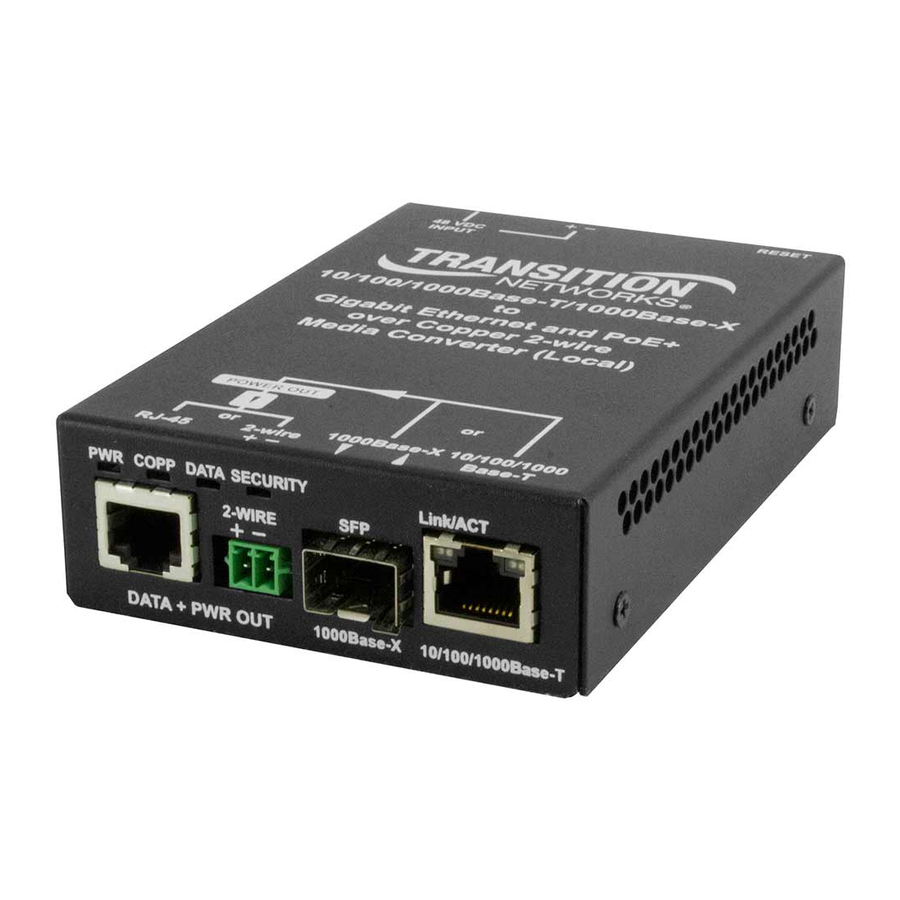
Page 11: Port Descriptions
Port Descriptions The extenders leverage existing 18-24 AWG unshielded twisted pair (CAT 5, CAT 3 and other 2-wire phone wire) cabling infrastructure to extend the Ethernet network at near Gigabit speeds and provide data and power to IP devices in remote locations. These extenders are used as a pair of devices, with a local and remote unit at opposite ends of the 2 Wire cable. -
Page 12: Installing Sfp Devices
Transition Networks SFPs are small form factor, hot-pluggable transceivers which allow for a single piece of network equipment to be connected to a multitude of interfaces, protocols, and transmission media via the SFP port. All Transition Networks SFPs are compliant with the Multi-Sourcing Agreement (MSA) ensuring interoperability with all other MSA compliant networking devices. - Page 13 Connect the male TX cable connector to the female RX connector. • Connect the male RX cable connector to the female TX connector. For information on available SFP modules, see the Transition Networks Small Form factor Pluggables webpage. For information on specific SFP characteristics, unpacking, installation, connecting, and removing see the specific SFP User Guide.
-
Page 14: Ethernet Cable Connection
Ethernet cable. Power over Ethernet Using the PoE option, the EO2Pxx4052-111 can automatically enable delivery of up to 25.5 watts of POE (IEEE 802.3at - Class 4) to compatible network devices, via its Ethernet port. -OR- Using the PoE option, the EO2PSE4052-111 can automatically enable delivery of up to 30 watts of power to the EO2PD4052-11. -
Page 15: Back Panel Device Power Options
2-Wire Connection Options Both 2-Wire options are shown and described below. Both are keyed slide-in options that are not screwed into the 2-Wire connector. Note the polarity for both options. 2 Position Terminal Block Plug Option (TN 28992) The provided 2 Position Terminal Block is a Female Socket 0.138" (3.50mm) 180°... -
Page 16: 48 Vdc In Options
48 VDC IN Options Local (EO2PSE4052-111) Power Input Options The power input options for the EO2PSE4052-111 (Local PSE unit) devices are: 1. 4-Pin mini DIN with the designated AC to DC adapter OR 2. 2-Pin Terminal Block connectors for +48 VDC power source that must meet IEEE 802.3 af/at isolation requirements of 1500VAC or 2250 VDC. -
Page 17: 4-Pin Mini Din Power Option
4-Pin Mini DIN Power Option The 48VDC IN 4-Pin Mini DIN power input option is shown and described below. Note: grip the power supply cable from the 48VDC IN 4-Pin Mini DIN connection with the flat-topped grip facing up; you will notice a slight slide before disconnection. Do not try to pull the connector from the 4-Pin Mini DIN by the cord itself as damage may occur. -
Page 18: Local Pse Unit Delivery Of Poe To Remote (End) Device
Local PSE Unit Delivery of PoE to Remote (End) Device If the remote end device (e.g., camera) does not need PoE, the remote unit does not provide PoE. If you do not want PoE power from the Remote unit to the connected remote (end) device, enable Auto Power Reset, select PoE Power Down mode, and ping an unused IP address on the subnet. -
Page 19: Operation
Please enter the correct password to access the web pages. Click the Ok button when done. The 2 Wire page then displays, as described in the next section. Note: Transition Networks strongly recommends you change your password immediately for security purposes. Transition Networks is not responsible for damages incurred due to insecure password protection. - Page 20 Messages: Forbidden You don’t have permission to access http://192.168.0.1/2wire.html on this server. 403 Error Please, wait until redirected or click on http://192.168.0.1/. Recovery: 1. Wait a few moments for the message to clear. 2. Click the on-screen link. 3. Log back in to the EO2P web GUI. Problem: An inactive web session never times out.
- Page 21 Remote Upgrade Status: displays the Remote Unit Automatic Upgrade Status page. Information Menu The Help selection (initial release) displays a link to this manual. Updated Help pages will display in release versions. Please visit Transition Networks EO2P Product Page, click on the Resources tab and download the latest manual.
-
Page 22: Wire Page
2 Wire page Navigate to the Configuration > 2 Wire page to view basic Local and/or Peer Unit parameters. Local Unit MAC Address: the EO2P Local unit’s MAC address (e.g., 00:c0:f2:58:3c:9d). Peer Unit MAC Address: the EO2P Remote (Peer) unit’s MAC address (e.g., 00:c0:f2:58:3c:9d). Phy Tx (Mbps): the EO2P unit’s Transmit speed (e.g., 928 Mbps). -
Page 23: Ip Page
IP page The IP page lets you configure and view IPv4, IPv6, and NTPv4/v6 Client parameters. IPv4 Configuration* *All changes except the DNS server will have effect after system boot. DHCP enabled: at the dropdown, select YES (enabled) or NO. The default is YES (enabled). - Page 24 DNS: displays the configured IPv4 DNS Server (e.g., 192.16.44.3). Additional address #1 - 2: two entry fields for optional additional IPv4 address / netmask. IPv6 configuration* *All changes except the DNS server will have effect after system boot. DHCP enabled: at the dropdown, select YES (enabled) or NO. The default is No (disabled).
- Page 25 IP page Buttons Ok: Click the Ok button to accept the current page parameter changes. Cancel: Click the Cancel button to negate the current page parameter changes and revert to the default parameter settings. Log Out: Click the Log Out button to exit EO2P Web Configuration. IP Addressing Note: EO2P units are intended to be fully managed through a single IP address.
-
Page 26: Ethernet Page
Ethernet page The Ethernet page lets you view the Combo Port parameters and configure Link Settings, SFP Detection Settings, Primary Link Mode, Powersaving parameters. Combo Port Speed: e.g., 100 or 1000 Mbps speed currently configured. Duplex: e.g., FULL_DUPLEX or HALF_DUPLEX mode. Link: e.g., YES if a link currently exists between Local and Remote units;... - Page 27 Link Settings *Set Autonegotiation Enable to what you want, save, and then change Autonegotiation Advertise or Link settings and save again. Autonegotiation Enable: at the dropdown select NO or YES. The default is YES (enabled). This setting affects the other settings in this section (Link Settings). Autonegotiation Advertise 1000Mbit Full Duplex: at the dropdown select NO or YES.
- Page 28 Powersaving Inactivity detection mode: at the dropdown, select Disabled or ETH link (enabled by Ethernet link) or ETH activity (enabled by Ethernet activity) as the power save trigger. The default is Disabled. Inactivity time(s): e.g., 300 seconds of inactivity will cause the EO2P to enter the Powersaving mode (only if Inactivity detection mode is set to Enabled).
-
Page 29: Device Page
Device page The Device page lets you configure and view hardware and software information, security password, and FTP and HTTP software updates. Hardware information Device Name: the device model (e.g., EO2PD4052-111 or EO2PSE4052-111). Device Description: e.g., Ethernet and Power over 2-Wire. Device Manufacturer: e.g., Transition. - Page 30 Software information Local EO2P FW Version: the local PSE unit’s current firmware version (e.g., 0.6.0.2). Remote EO2P FW Version: the remote PD unit’s current firmware version (e.g., 0.6.0.2). On the remote PD unit, displays the message “Use Device page to directly manage Remote Unit”.
- Page 31 Device page Buttons Ok: Click the Ok button to accept the current page parameter changes. Cancel: Click the Cancel button to negate the current page parameter changes and revert to the default parameter settings. Log Out: Click the Log Out button to exit EO2PD4052-111 Web Configuration. Device page Messages Message: Performing Hardware Reset Please wait until your modem finishes initializing...
-
Page 32: Firmware Upgrade Procedures
Firmware Upgrade Procedures All upgrades require accessing the Device page in the web interface which requires that you are logged in. You may need to login as the sessions timeout and reboots clear the sessions. Login with the password ( by default) when asked. - Page 33 The message “This page is updated automatically every 10 seconds. The modem must be reset once the upgrade has finished.” displays. 5. When the message “Ready: finished correctly” displays, click the Hardware Reset button. The message “Performing Hardware Reset Please wait until your modem finishes initializing...”...
-
Page 34: Notes On Fw Upgrade
Notes on FW Upgrade 1. The Local Unit can handle either a Local or a Remote upgrade file, assuming the remote unit is attached and up and running. 2. The Remote Unit can only handle a Remote FW update file. 3. -
Page 35: Tftp Fw Upgrade
There is a single update file for both the Local and Remote Units. Notes for SW Update Note: this procedure should only be used at the direction of Transition Networks Technical Support. Currently, TFTP/FTP updates do not do the necessary steps to have the Remote Unit upgrade automatically to match the local version. -
Page 36: Auto Power Reset Page
Auto Power Reset page The Auto Power Reset (ping reset) page lets you enable and configure APR mode parameters and view current status. Auto Power Reset (APR) monitors the connected PoE+ device and can restart it if it is unresponsive. Note: If the remote device does not need PoE, the remote unit does not provide PoE. - Page 37 reset and the sequence re-started. Use this mode if you are unsure how long the end device takes to respond. In this mode you must configure all page parameters (described below). Timeout Mode: basic mode where all attached devices are pinged until ping fails. No pinging occurs during the configurable Device Reboot Time.
-
Page 38: Advanced Page
Advanced page The Advanced page lets you configure and view EO2P broadcast suppression and perform a hardware reset and factory reset. Hardware Reset: click the Hardware Reset button to perform a reset to factory default settings on the EO2P. Momentarily displays the message “Performing Hardware Reset Please wait until your modem finishes initializing...”... - Page 39 Advanced page Messages Message: The password you entered is incorrect Meaning: Error in Factory Reset Recovery: Wait until you are redirected or click return to main page... Message: Performing Factory Reset Please, wait until your modem finishes the initialization... Meaning: A factory reset from the Configuration > Advanced menu path is in process. Recovery: Wait a few moments for the Advanced page factory reset to complete.
-
Page 40: Power And Power (No Auto Update) Pages
Power and Power (No Auto Update) pages The Power and Power (No Auto Update) pages let you view the current EO2P current, voltage, power, power supply, and power over 2 wire status information. Power Information Local 2-Wire Output Current: displays the local EO2P 2 Wire output current in mA. Local 2-Wire Output Voltage: displays the local EO2P 2 Wire output voltage in Volts. - Page 41 Remote PD Output Power: displays the remote powered device’s output power in Watts. External Power Supply Voltage: displays the local and remote EO2P input voltage measurements in Volts. Power over 2-Wire Status Class Detection Status: e.g., Hunting for Classification Code, or Classification Code Detected. Class Mismatch: e.g., Classification Codes Match, or Classification Codes Mismatch.
-
Page 42: Sfp And Sfp (No Auto Update) Pages
SFP and SFP (No Auto Update) pages The SFP and SFP (No Auto Update) pages let you view SFP and DMI information for both the Local and Remote EO2P devices. The fields are blank if no SFPs are connected. SFP Information Vendor: the SFP maker (e.g., Transition) for the Local and Remote EO2P devices. - Page 43 Remote Upgrade Status Navigate to the Status > Remote Upgrade Status menu path to display the Remote Unit Automatic Upgrade Status. After updating the Local Unit and rebooting to a new version, the Remote Unit will automatically upgrade. Use this page to monitor the Remote Unit's upgrade progress. This page is updated automatically every 10 seconds.
-
Page 44: Back Panel Reset Button Functions
Back Panel RESET Button Functions The EO2P back panel RESET button is used for other functions besides Pairing / Unpairing the units for secure (encrypted) 2 Wire network operation. You press and hold the RESET button for different periods of time to perform different functions; the LEDs blink at different rates to indicate the function selected. - Page 45 Security Pairing & Unpairing Devices via the RESET button Transmission between the Local and Remote units can be encrypted using AES 128-bit encryption as described below. Note: If performing pairing / security encryption, you may want to perform these steps before final deployment of Local PSE and Remote PD units in the field.
-
Page 46: Status Leds
Status LEDs The EO2Pxx4052-111 provides multiple LEDs for status and diagnostics of the Ethernet, Cat 3/Cat5 and POE functions. Use the status LEDs to monitor EO2Pxx4052-111 operation in the network. Local PSE Unit Remote PD Unit PWR: Power and bootloader status:... - Page 47 Link/ACT: 1GE TP or Fiber port: 1000Mbps: Green - ON link, BLINK activity 100Mbps: Green and Yellow - ON link, BLINK activity 10Mbps: Yellow - ON link, BLINK activity POE – Power Over Ethernet status (Remote PD unit only): No PD detected: Power applied: Green –...
-
Page 48: Technical Specifications
45 Watts max. See Throughput, Power, and Power Consumption page 51. EO2Pxx4052-111: 3.25” [82.5 mm] Wide x 1.25" [31.75 mm] Deep x 5.38” [136.7 mm] High Dimensions Power Adapter: 2.25 x 6 x 1.31 inches (5.72 x 15.25 x 3.32 cm) EO2xxx4052-111: 0.85 lb. -
Page 49: Power Supply 25148 Specifications
Supplies do not provide redundant or load sharing capabilities. The Power Supply has a blue LED to indicate the presence of power to the Power Supply. The EO2P PWR LED will blink to indicate the presence of power to the EO2Pxx4052-111. Universal AC input / Full range... - Page 50 EMC Emission: Compliance to EN55022 class B, EN61000-3-2,3, FCC PART 15 / CISPR22 class B, CNS13438 class B, GB9254, GB17625.1 EMC Immunity: Compliance to EN61000-4-2,3,4,5,6,8,11, light industry level, criteria A MTBF: 348.7K hrs min. MIL-HDBK-217F(25℃) Dimensions: 145*60*32mm (L*W*H) 33706 Rev. A EO2P User Guide |Page 50...
-
Page 51: Throughput, Power, And Distance Worksheets
Throughput, Power, and Distance Worksheets This section provides static examples of the calculation worksheets available. For the latest power and distance over 2-wire or multi-pair cable, view the online calculators at https://www.transition.com. The figures below contain data transfer rates and PoE available for the EO2P extenders as a function of wire length. -
Page 52: Ethernet Over 2-Wire Power Distance Calculator
This calculator should only be used for Transition Networks' Ethernet Over 2-Wire Extender With PoE+ to provide approximate maximum distance and power calculation. Actual results may vary due to cable quality and other conditions. To accommodate for variations, we recommend reducing cable length by 5% or reducing power by 2-3%. -
Page 53: Rj45 Cable Configurations
RJ45 Cable Configurations Install a straight-through RJ45 connectorized cable between Local unit DATA + PWR OUT and the Remote unit DATA + PWR IN RJ45 connectors. The cable can be fully pinned or can use various pin combinations of each connector. Supported RJ-45 cable configurations are described below. - Page 54 There are pin number designations for each color in T-568B and T-568A. T-568A Pins Pin # Color Designation Green Stripe Green Orange Stripe Blue Not Used Blue Stripe Not Used Orange Brown Stripe Not Used Brown Not Used T-568B Pins Pin # Color Designation...
-
Page 55: Troubleshooting
Troubleshooting Troubleshooting Procedures If the EO2P fails, isolate and correct the fault by determining the answers to the following questions and then taking the indicated action. First isolate the problem to the EO2P; troubleshoot any other network gear (Ethernet switch, remote cameras, etc.) to isolate the problem to the EO2P. EO2PSE4052-111 Local PSE Unit EO2PD4052-111 Remote PD Unit 1. -
Page 56: Record Model And System Information
6. Describe actions already taken to resolve the problem (e.g., change mode, reset, etc.): ________ _________________________________________________________________________________ _________________________________________________________________________________ _________________________________________________________________________________ 7. The model # and serial # of other Transition Networks products in the network: _____________ _________________________________________________________________________________ _________________________________________________________________________________ 8. Describe your network environment (layout, cable type, cable distance, etc.): ________________... -
Page 57: Warranty
In no event shall Transition Networks be liable for incidental or consequential damages, costs, or expenses arising out of or in connection with the performance of the product delivered hereunder. Transition Networks will in no case cover damages arising out of the product being used in a negligent fashion or manner. -
Page 58: Contact Us
Networks for a fee will carry a 180-day limited warranty. All warranty claims are subject to the restrictions and conventions set forth by this document. Transition Networks reserves the right to charge a $50 fee for all testing and shipping incurred, if after testing, a return is classified as “No Problem Found.”... -
Page 59: Fcc Regulations
In accordance with European Union Directive 2002/96/EC of the European Parliament and of the Council of 27 January 2003, Transition Networks will accept post usage returns of this product for proper disposal. The contact information for this activity can be found in the 'Contact Us' portion of this document. -
Page 60: Record Of Revisions
Trademarks Notice: All trademarks and registered trademarks are the property of their respective owners. Copyright Restrictions: © 2017 Transition Networks. All rights reserved. No part of this work may be reproduced or used in any form or by any means - graphic, electronic or mechanical - without written permission from Transition Networks. -
Page 61: Contact Us
Contact Us 10900 Red Circle Drive Minnetonka, MN 55343 USA telephone: +1.952.941.7600 toll Free: 800.526.9267 fax: 952.941.2322 sales@transition.com info@transition.com techsupport@transition.com www.transition.com/ 33706 Rev. A EO2P User Guide |Page 61...
Need help?
Do you have a question about the EO2Pxx4052-111 and is the answer not in the manual?
Questions and answers