
Related Manuals for TMQ Bosun-AP9


Summary of Contents for TMQ Bosun-AP9
- Page 1 TMQ Bosun - AP9 (Ver 4 Rev 1 935) OPERATION AND INSTALLATION MANUAL www.tmq.com.au...
- Page 2 This Page is Blank TMQ Bosun - AP9 Rev1 (935) Page 2 16/06/2003...
-
Page 3: Table Of Contents
Mechanical Motor Installation ................34 NMEA I ................... 36 NPUT ONNECTIONS Data In .........................36 Programming the GPS unit..................36 Heading Data Input .....................37 Heading Data Output...................37 ....................38 XTERNAL LARM ................... 39 OMPASS ALIBRATION TMQ Bosun - AP9 Rev1 (935) Page 3 16/06/2003... - Page 4 PCB O ..................57 ISPLAY VERLAY PCB O ..................58 ONTROL VERLAY AP9 S ..................59 OMPLETE CHEMATIC PCB S .................... 60 CHEMATIC PCB S ..................61 ISPLAY CHEMATIC ......................62 ARRANTY TMQ Bosun - AP9 Rev1 (935) Page 4 16/06/2003...
-
Page 5: Warning
IT IS NOT RECOMMENDED THAT THE AUTOPILOT BE USED WHILE NAVIGATING IN RESTRICTED WATERWAYS WATER CURRENTS, WIND CHANGES RADIO TRANSMITTER INTERFERENCE MAY AFFECT VESSEL COURSE SUFFICIENTLY TO ENDANGER YOUR OWN OR OTHER VESSELS. TMQ Bosun - AP9 Rev1 (935) Page 5 16/06/2003... -
Page 6: Introduction
These are very robust units, which will not be adversely affected by water. The abilities they provide are somewhat different from the main control panel. See the Operation section of this manual for details. TMQ Bosun - AP9 Rev1 (935) Page 6 16/06/2003... -
Page 7: System Overview
• GPS Mode When receiving information from a GPS unit, the autopilot can steer a vessel along a preset track to a latitude and longitude. TMQ Bosun - AP9 Rev1 (935) Page 7 16/06/2003... - Page 8 For vessels under survey requirements, the timer can be "locked" on to provide a warning alarm at any fixed interval and an output for a loud external alarm if alarm not reset within 1 minute of beginning to sound. TMQ Bosun - AP9 Rev1 (935) Page 8 16/06/2003...
-
Page 9: Modes Of Operation
Possible alarms • Stopwatch timer alarm If the option of Electric steering is enabled, this mode may not be available and the unit will go direct to power steer on turn on. TMQ Bosun - AP9 Rev1 (935) Page 9 16/06/2003... -
Page 10: Auto Mode
The rate-of-turn control on the front panel sets the maximum number of degrees per second that the vessel will turn through. This rate-of-turn control applies in AUTO and GPS modes ONLY. See the separate section on Rate-of-Turn for more information. TMQ Bosun - AP9 Rev1 (935) Page 10 16/06/2003... -
Page 11: Power Steering Mode
Steering Levers), Refer to the diagrams detailing remote unit connections. If your vessel requires counter-rudder while steering in auto mode, you may wish to set the counter rudder control to "1" (ie: disabled) while using power-steer. TMQ Bosun - AP9 Rev1 (935) Page 11 16/06/2003... -
Page 12: Gps Mode
No GPS Data alarm shall sound. Disengaging GPS Mode • Pressing the "Auto" key will set the Bosun to Auto Mode. • Pressing the "Standby" key will return the pilot to Standby. TMQ Bosun - AP9 Rev1 (935) Page 12 16/06/2003... - Page 13 If only the XTE information is available from your GPS unit then your vessel must be on track, and heading in the correct direction before engaging the GPS mode, and the auto-sequencing feature is not available. TMQ Bosun - AP9 Rev1 (935) Page 13 16/06/2003...
- Page 14 GPS Mode steering. • Ensure that the GPS unit has the correct magnetic correction factor. • Ensure that the Bosun compass is correctly aligned and installed. TMQ Bosun - AP9 Rev1 (935) Page 14 16/06/2003...
-
Page 15: Stopwatch Timer Mode
NOT be displayed. Selecting a stopwatch time of zero will disable this feature. If the Commercial watch alarm feature is enabled, the timer alarm delay in all modes except standby is fixed. TMQ Bosun - AP9 Rev1 (935) Page 15 16/06/2003... -
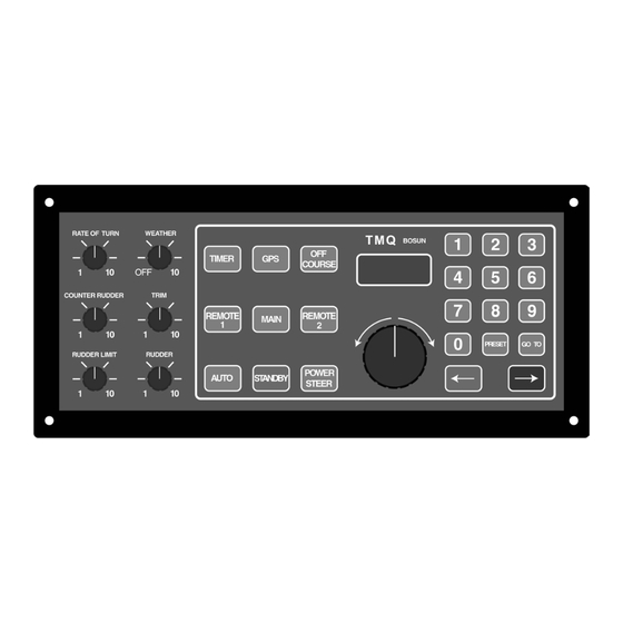
Page 16: Controls
Rate of turn is also controlled by the rudder limit and rudder ratio controls. A course-change entered from one of the remote steering stations is not controlled by the rate-of-turn knob. TMQ Bosun - AP9 Rev1 (935) Page 16 16/06/2003... -
Page 17: Weather
This will give the straightest possible course. In poor weather, reduce this setting to prevent over-working the steering. Rotating this control fully anti-clockwise will turn off power to the Bosun autopilot. TMQ Bosun - AP9 Rev1 (935) Page 17 16/06/2003... -
Page 18: Counter-Rudder
Once the correct setting is found for your vessel, it should not need to be changed. TMQ Bosun - AP9 Rev1 (935) Page 18 16/06/2003... -
Page 19: Trim
With the vessel travelling ahead, switch the autopilot to power steer mode. Adjust the trim control until the ship steers straight. The trim control is not intended to be used for adjusting the vessel course in auto or power steer mode. TMQ Bosun - AP9 Rev1 (935) Page 19 16/06/2003... -
Page 20: Rudder Limit
Under normal operation the external rudder limit control is set at maximum. See the Adjustments chapter of the Installation section of this manual. TMQ Bosun - AP9 Rev1 (935) Page 20 16/06/2003... -
Page 21: Rudder (Rudder Ratio) Control
When the rudder setting is too low, turns will take an excessive amount of time, and the vessel may "wander". When the rudder setting is too high, turns will be rapid and the vessel will oversteer. TMQ Bosun - AP9 Rev1 (935) Page 21 16/06/2003... -
Page 22: Installation And Configuration
Installation and Configuration Installation Requirements To reduce the risk of operating problems, all TMQ equipment and cables connected to it should be at least 1 metre (3 feet) from any equipment transmitting or cables carrying radio signals. e.g. VHF Radios, cables and antennas. -
Page 23: Compass Installation
Before fixing the sensor in place, align it carefully so that the Bosun compass displays the same bearing as the ships compass. The compass top TMQ Bosun - AP9 Rev1 (935) Page 23 16/06/2003... -
Page 24: Installing A Magnetic Sensor Unit (Fluxgate)(Commag)
Fasten the compass bracket with non-magnetic screws. The compass must be mounted in a near vertical position. See also the diagram "Fluxgate Compass Mounting Options". TMQ Bosun - AP9 Rev1 (935) Page 24 16/06/2003... - Page 25 Ensure good contact is made between cable conductors and terminal strip connectors. If the compass cable is required to be longer, contact TMQ for a Compass Extension Cable. TMQ Bosun - AP9 Rev1 (935)
- Page 26 Bosun compass, although in most cases the factory calibration will be as good as or better than calibration achieved on the vessel. See the Compass Calibration Section. TMQ Bosun - AP9 Rev1 (935) Page 26 16/06/2003...
-
Page 27: Interchanging Magnetic Sensor Unit & Compass Top Sensor
Rear cover must be temporally removed to access the switches). For magnetic sensor unit ) switch 3 and 4 to OFF (COMMAG/ Fluxgate For compass top sensor (CTS) switch 3 and 4 to ON TMQ Bosun - AP9 Rev1 (935) Page 27 16/06/2003... -
Page 28: Rudder Feedback
+ 5 volts Red or brown wire Terminal Rud: Signal Green Terminal Neg: Negative Blue wire If a RFUS is used SW1 (Dip switch) switch 1 & 2 should be set to OFF. TMQ Bosun - AP9 Rev1 (935) Page 28 16/06/2003... -
Page 29: Heavy Duty Rudder Feedback Installation Diagram
Heavy Duty Rudder Feedback Installation Diagram TMQ Bosun - AP9 Rev1 (935) Page 29 16/06/2003... -
Page 30: Standard Rudder Feedback Installation Diagram
Standard Rudder Feedback Installation Diagram TMQ Bosun - AP9 Rev1 (935) Page 30 16/06/2003... - Page 31 THE RUDDER FEEDBACK UNIT IS FACTORY ALIGNED. THE ARM SHOULD NOT BE REMOVED OR LOOSENED UNNECESSARILY. IF ARM IS LOOSENED REMOVED, VOLTAGE ALIGNMENT SHOULD BE CHECKED BEFORE USING AUTOPILOT. COMPETENT TECHNICIAN MUST DO THIS. TMQ Bosun - AP9 Rev1 (935) Page 31 16/06/2003...
-
Page 32: Remote Units
Select 2 Remote 2 Logic Signal PWR/STBY/AUTO Wiper 2 Remote 2 Trim Signal or Wheel Input Select 1 Remote 1 Logic Signal PWR/STBY/AUTO Wiper 1 Remote 1 Trim Signal or Wheel Input TMQ Bosun - AP9 Rev1 (935) Page 32 16/06/2003... -
Page 33: Drive Installation
Follow any instructions of the Hydraulic Steering supplier. The AP9 Bosun autopilot can drive spool valves, relays or hydraulic pumps. TMQ can supply the following pump units: A constant running pump set (including spool valves) for 24V DC operation with flow rate up to 4000cc per minute. -
Page 34: Mechanical Motor Installation
Mechanical Motor Installation Motor Gearing Ratio Mechanical drive motors supplied by TMQ Electronics have a nominal output speed of 30 RPM. They are fitted with a 16 tooth 3/8 pitch sprocket to suit B.S. chain (06B-1R). 1.5 meters of chain, a 38 tooth sprocket and mounting bolts are supplied in the installation kit. - Page 35 If steering problems are encountered with the TMQ mechanical units, different sprockets can be fitted on the motor drive shaft; the variations normally available from the factory are 10 or 24 tooth.
-
Page 36: Nmea Input Connections
NMEA 0183 format data containing APA or APB or both XTE and BOD information. For more information on this, see the Operations section of this manual and consult your GPS unit manual TMQ Bosun - AP9 Rev1 (935) Page 36 16/06/2003... -
Page 37: Heading Data Input
Gyro or GPS Gyro. Heading Data Output Heading Data Output is on DATA OUT 1 (Positive) and NEGATIVE (Negative) of the NMEA Data Terminal T4. TMQ Bosun - AP9 Rev1 (935) Page 37 16/06/2003... -
Page 38: External Alarm
(T6), terminals 10 V and AL (EXT AL). The AL output will be 10 volts when the alarm is not sounding (with alarm connected), and approximately 0 volts when active. TMQ recommends a 12-volt piezo buzzer with maximum current draw not exceeding 250 milliamps be connected to this output. -
Page 39: Compass Calibration
3. Turn vessel slowly through two complete circles in same direction. 4. When the circles are complete, enter "902" by using the keypad, then hold down GOTO, press STANDBY, then release both buttons together. TMQ Bosun - AP9 Rev1 (935) Page 39 16/06/2003... - Page 40 If you are unsure of the success of the calibration, you may return to the factory calibration setting by entering "903", hold down GOTO, press STANDBY, then release both buttons together. ‘rES’ will be displayed for approximately 1 second. TMQ Bosun - AP9 Rev1 (935) Page 40 16/06/2003...
-
Page 41: Rudder Limit Adjustment
This will cause any port drive command to be ignored and turn off the port drive light on the front panel. • The starboard limit S_L functions in the same way for rudder angles to starboard. TMQ Bosun - AP9 Rev1 (935) Page 41 16/06/2003... - Page 42 3. Set the rudder to the required Port position and press Port Arrow Button 4. Set the rudder to the required Starboard position and press Stbd Arrow Button 5. To store the Data press "GOTO" TMQ Bosun - AP9 Rev1 (935) Page 42 16/06/2003...
-
Page 43: Ap9 Special Modes
Not Used. Option remote: (Refer to the Connection Diagrams to select Required Remote Mode) Remote Mode 1 ( 2 Standard TMQ Remotes) • Remote Unit 1 on Input “Wiper 1” with Control Line “Select 1” being held Negative for Auto, Positive for Power Steer. - Page 44 • No voltage on Control Line “Select 1” or Control line “Select 2”, Autopilot returns to Standby. Remote Mode 2 (TMQ Active Remote) • Remote Input on Input “Wiper 1” with Control Line “Select 1” being pulsed negative for Auto, Positive for Power Steer.
-
Page 45: Ap9 Connection / Wiring Diagrams
AP9 Connection / Wiring Diagrams Connection Layout TMQ Bosun - AP9 Rev1 (935) Page 45 16/06/2003... -
Page 46: Pump Or Drive Connections
Pump or Drive Connections TMQ Bosun - AP9 Rev1 (935) Page 46 16/06/2003... -
Page 47: Remote Mode 1, 2 Standard Remotes - Reversing Pump
Remote Mode 1, 2 Standard Remotes - Reversing Pump TMQ Bosun - AP9 Rev1 (935) Page 47 16/06/2003... -
Page 48: Remote Mode 1, 2 Std Remotes - Continuous Running Pump
Remote Mode 1, 2 Std Remotes - Continuous Running Pump TMQ Bosun - AP9 Rev1 (935) Page 48 16/06/2003... -
Page 49: Remote Mode 2, 1 Active Remote
Remote Mode 2, 1 Active Remote TMQ Bosun - AP9 Rev1 (935) Page 49 16/06/2003... -
Page 50: Remote Mode 3, 1 Remote And 1 Electric Steering Input
Remote Mode 3, 1 Remote and 1 Electric Steering Input TMQ Bosun - AP9 Rev1 (935) Page 50 16/06/2003... -
Page 51: Remote Mode 5, 3 Electric Steering Inputs
Remote Mode 5, 3 Electric Steering Inputs TMQ Bosun - AP9 Rev1 (935) Page 51 16/06/2003... -
Page 52: Optional Extras
There are a range of optional extras that can be connected to the C-Drive system as the need or circumstances require. The C-Drive system can be adapted to suit many applications. Further information can be obtained from the TMQ website at www.tmq.com.au Rudder Angle Indicator... -
Page 53: Remotes
AP500 Head The AP500 head provides full control of the autopilot, indicates both current course and course to steer along with rudder angle. TMQ Bosun - AP9 Rev1 (935) Page 53 16/06/2003... -
Page 54: Hydraulic Drives And Pump Units
Continuous pumps Constant running pumps available in 2 or 3 litre for 24 volt DC systems. Accurate flow adjustment to set lock to lock time. TMQ Bosun - AP9 Rev1 (935) Page 54 16/06/2003... - Page 55 Supplied with standard chain and socket. Computer Software TMQ AP1000 Autopilot operating Software. Computer control program enabling autopilot control from a standard PC with serial com ports. (Cable required) TMQ Bosun - AP9 Rev1 (935) Page 55 16/06/2003...
-
Page 56: Main Pcb Overlay
Main PCB Overlay TMQ Bosun - AP9 Rev1 (935) Page 56 16/06/2003... -
Page 57: Display Pcb Overlay
Display PCB Overlay TMQ Bosun - AP9 Rev1 (935) Page 57 16/06/2003... -
Page 58: Control Pcb Overlay
Control PCB Overlay TMQ Bosun - AP9 Rev1 (935) Page 58 16/06/2003... -
Page 59: Complete Ap9 Schematic
Complete AP9 Schematic TMQ Bosun - AP9 Rev1 (935) Page 59 16/06/2003... -
Page 60: Main Pcb Schematic
Main PCB Schematic TMQ Bosun - AP9 Rev1 (935) Page 60 16/06/2003... -
Page 61: Display Pcb Schematic
Display PCB Schematic TMQ Bosun - AP9 Rev1 (935) Page 61 16/06/2003... -
Page 62: Warranty
Warranty TMQ Electronics products are thoroughly inspected and tested before shipment from the factory and are warranted to be free of defects in workmanship and materials for a period of one year from the date of shipment from the factory. By returning the enclosed questionnaire and registering the product. - Page 63 TMQ Electronics shall not be liable for damage or loss incurred resulting from the use and operation of this product. TMQ Electronics reserves the right to make changes or improvements to later models without incurring the obligation to install similar changes to equipment already supplied.
Need help?
Do you have a question about the Bosun-AP9 and is the answer not in the manual?
Questions and answers