Table of Contents
Advertisement
Quick Links
Проконсультироваться и купить данное оборудование вы можете в компании «АНД-Системс»
адрес: 125480, г.Москва, ул.Туристская, д.33/1; site: https://andpro.ru тел: +7 (495) 545-4870 email: info@andpro.ru
При обращении используйте промокод AND-PDF и получите скидку.
S
UPER
®
S
S
S
UPER
TORAGE
YSTEM
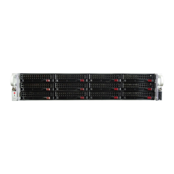
5028R-E1CR12L
USER'S MANUAL
1.0
Advertisement
Table of Contents

Related Manuals for Supero 5028R-E1CR12L

Summary of Contents for Supero 5028R-E1CR12L
- Page 1 Проконсультироваться и купить данное оборудование вы можете в компании «АНД-Системс» адрес: 125480, г.Москва, ул.Туристская, д.33/1; site: https://andpro.ru тел: +7 (495) 545-4870 email: info@andpro.ru При обращении используйте промокод AND-PDF и получите скидку. UPER ® UPER TORAGE YSTEM 5028R-E1CR12L USER’S MANUAL...
- Page 2 The information in this User’s Manual has been carefully reviewed and is believed to be accurate. The vendor assumes no responsibility for any inaccuracies that may be contained in this document, makes no commitment to update or to keep current the information in this manual, or to notify any person or organization of the updates.
-
Page 3: About This Manual
SC826BE1C-R920LPB chassis. Chapter 2: Server Installation This chapter describes the steps necessary to install the 5028R-E1CR12L into a rack and check out the server configuration prior to powering up the system. If your server was ordered without processor and memory components, this chapter will refer you to the appropriate sections of the manual for their installation. - Page 4 UPER TORAGE YSTEM 5028R-E1CR12L User's Manual Chapter 5: Advanced Motherboard Setup Chapter 5 provides detailed information on the X10SRH-CLN4F motherboard, including the locations and functions of connections, headers and jumpers. Refer to this chapter when adding or removing processors or main memory and when reconfiguring the motherboard.
- Page 5 Preface Notes...
-
Page 6: Table Of Contents
UPER TORAGE YSTEM 5028R-E1CR12L User's Manual Table of Contents Chapter 1 Introduction Overview ......................1-1 Motherboard Features ..................1-2 Processors ...................... 1-2 Memory ......................1-2 SATA ........................ 1-2 SAS ......................... 1-2 I/O Ports ......................1-2 PCI Expansion Slots ..................1-2 Onboard Graphics ................... - Page 7 Table of Contents NIC1 ........................ 3-2 NIC2 ........................ 3-2 HDD ......................... 3-3 Power ......................3-3 Drive Carrier LEDs ..................3-3 Chapter 4 Standardized Warning Statements for AC Systems About Standardized Warning Statements ............4-1 Warning Definition ................... 4-1 Installation Instructions ..................4-4 Circuit Breaker ....................
- Page 8 UPER TORAGE YSTEM 5028R-E1CR12L User's Manual Jumper Settings .................... 5-20 5-10 Onboard Indicators ..................5-22 5-11 SATA Drive Ports ................... 5-23 5-12 Installing Software ..................5-24 SuperDoctor® 5 .................... 5-25 5-13 Onboard Battery .................... 5-26 Chapter 6 Advanced Chassis Setup Static-Sensitive Devices ..................
-
Page 9: Chapter 1 Introduction
Chapter 1 Introduction Overview The 5028R-E1CR12L is a high-end storage system comprised of two main subsys- tems: the SC826BE1C-R920LPB 2U/rackmount chassis and the X10SRH-CLN4F motherboard. Please refer to our web site for information on operating systems that have been certified for use with the system (www.supermicro.com). -
Page 10: Motherboard Features
YSTEM 5028R-E1CR12L User's Manual Motherboard Features The 5028R-E1CR12L is built around the X10SRH-CLN4F, a single processor moth- erboard based on Intel's C612 Express chipset. Below are the main features of the X10SRH-CLN4F (see Figure 1-1 for a block diagram of the chipset). -
Page 11: Onboard Graphics
Chapter 1: Introduction Onboard Graphics The X10SRH-CLN4F provides onboard grpahics with a AST 2400 graphics control- ler. Server Chassis Features The SC826BE1C-R920LPB is a 2U form factor chassis designed to be used in a storage configuration. The following is a general outline of the main features of the SC826BE1C-R920LPB chassis. -
Page 12: System Block Diagram
UPER TORAGE YSTEM 5028R-E1CR12L User's Manual Figure 1-1. Intel C612 Express Chipset: System Block Diagram Note: This is a general block diagram. Please see Chapter 5 for details. VR12.5 5 PHASE 145W Haswell Skt-R3 LGA2011-3 DMI2 MINI SAS HD LSI SAS3008... - Page 13 Chapter 1: Introduction Figure 1-2. X10SRH-CLN4F Motherboard JUIDB1 UID-LED UID-SW 1 2 3 COM1 USB0/1 USB2/3(3.0) i350 LEDM1 JPL1 FAN5 FAN4 IPMI_LAN LAN2/LAN4 LAN1/LAN3 JVR1 USB4/5 USB6/7 USB8/9 BIOS JPS1 JOH1 JL1 CHASSIS INTRUSION JBT1 JBR1 C610 LGA2011-3 X10SRH-CF LEDS1 JPSAS1 REV: 1.00...
-
Page 14: Contacting Supermicro
UPER TORAGE YSTEM 5028R-E1CR12L User's Manual Contacting Supermicro Headquarters Address: Super Micro Computer, Inc. 980 Rock Ave. San Jose, CA 95131 U.S.A. Tel: +1 (408) 503-8000 Fax: +1 (408) 503-8008 Email: marketing@supermicro.com (General Information) support@supermicro.com (Technical Support) Web Site: www.supermicro.com... -
Page 15: Chapter 2 Server Installation
Unpacking the System You should inspect the box the 5028R-E1CR12L was shipped in and note if it was damaged in any way. If the server itself shows damage you should file a damage claim with the carrier who delivered it. -
Page 16: Rack Precautions
UPER TORAGE YSTEM 5028R-E1CR12L User's Manual • This product is for installation only in a Restricted Access Location (dedicated equipment rooms, service closets and the like). • This product is not suitable for use with visual display work place devices acccording to §2 of the the German Ordinance for Work with Visual Display... -
Page 17: Rack Mounting Considerations
Chapter 2: Server Installation Rack Mounting Considerations Ambient Operating Temperature If installed in a closed or multi-unit rack assembly, the ambient operating tempera- ture of the rack environment may be greater than the ambient temperature of the room. Therefore, consideration should be given to installing the equipment in an environment compatible with the manufacturer’s maximum rated ambient tempera- ture (Tmra). -
Page 18: Installing The System Into A Rack
UPER TORAGE YSTEM 5028R-E1CR12L User's Manual Installing the System into a Rack This section provides information on installing the SC826 chassis into a rack unit with the quick-release rails provided. There are a variety of rack units on the market, which may mean the assembly procedure will differ slightly. - Page 19 Chapter 2: Server Installation Figure 2-1: Separating the Rack Rails Separating the Inner and Outer Rails Rail Assembly SCREW 1. Locate the rail assembly in the chassis packaging. Extending the Rails 2. Extend the rail assembly by pulling it outward. 3.
-
Page 20: Outer Rack Rails
UPER TORAGE YSTEM 5028R-E1CR12L User's Manual SCREW screw the handles the outer rails for secure purpose if necessary Figure 2-2. Assembling the Outer Rails Outer Rack Rails Outer rails attach to the rack and hold the chassis in place. The outer rails for the SC826 chassis extend between 30 inches and 33 inches. - Page 21 Chapter 2: Server Installation SCREW Figure 2-3. Installing the Rack Rails Installing the Chassis into a Rack Note: do not pick up the server with the front handles. They are designed to pull the system from a rack only. 1. Extend the outer rails as illustrated above. 2.
- Page 22 UPER TORAGE YSTEM 5028R-E1CR12L User's Manual Notes...
-
Page 23: Chapter 3 System Interface
Chapter 3: System Interface Chapter 3 System Interface Overview There are several LEDs on the control panel as well as others on the drive carri- ers to keep you constantly informed of the overall status of the system as well as the activity and health of specific components. -
Page 24: Control Panel Leds
UPER TORAGE YSTEM 5028R-E1CR12L User's Manual Control Panel LEDs The control panel located on the front of the chassis has several LEDs. These LEDs provide you with critical information related to different parts of the system. This section explains what each LED indicates when illuminated and any corrective action you may need to take. -
Page 25: Hdd
Chapter 3: System Interface On the 5028R-E1CR12L, this LED indicates hard drive activity when flashing. Power Indicates power is being supplied to the system's power supply units. This LED should normally be illuminated when the system is operating. Drive Carrier LEDs Each drive carrier has two LEDs: •... - Page 26 UPER TORAGE YSTEM 5028R-E1CR12L User's Manual Notes...
-
Page 27: About Standardized Warning Statements
Chapter 4: Warning Statements for AC Systems Chapter 4 Standardized Warning Statements for AC Systems About Standardized Warning Statements The following statements are industry standard warnings, provided to warn the user of situations which have the potential for bodily injury. Should you have questions or experience difficulty, contact Supermicro's Technical Support department for assistance. - Page 28 UPER TORAGE YSTEM 5028R-E1CR12L User's Manual Warnung WICHTIGE SICHERHEITSHINWEISE Dieses Warnsymbol bedeutet Gefahr. Sie befinden sich in einer Situation, die zu Verletzungen führen kann. Machen Sie sich vor der Arbeit mit Geräten mit den Gefahren elektrischer Schaltungen und den üblichen Verfahren zur Vorbeugung vor Unfällen vertraut.
- Page 29 Warning Statements for AC Systems جسذٌة اصابة ًتتسبب ف حالة ٌوكي أى ًاًك ف خطز ًٌٌع هذا الزهز !تحذٌز الذوائز بالوخاطز الٌاجوة عي ي على علن ، ك هعذات تعول على أي قبل أى الكهزبائٍة حىادث أي وقىع وٌع ل الىقائٍة...
-
Page 30: Installation Instructions
UPER TORAGE YSTEM 5028R-E1CR12L User's Manual Installation Instructions Warning! Read the installation instructions before connecting the system to the power source. 設置手順書 システムを電源に接続する前に、 設置手順書をお読み下さい。 警告 将此系统连接电源前,请先阅读安装说明。 警告 將系統與電源連接前,請先閱讀安裝說明。 Warnung Vor dem Anschließen des Systems an die Stromquelle die Installationsanweisungen lesen. -
Page 31: Circuit Breaker
Chapter 4: Warning Statements for AC Systems Circuit Breaker Warning! This product relies on the building's installation for short-circuit (overcurrent) protection. Ensure that the protective device is rated not greater than: 250 V, 20 A. サーキッ ト ・ ブレーカー この製品は、 短絡 (過電流) 保護装置がある建物での設置を前提としています。 保護装置の定格が250 V、... -
Page 32: Power Disconnection Warning
UPER TORAGE YSTEM 5028R-E1CR12L User's Manual 경고! 이 제품은 전원의 단락(과전류)방지에 대해서 전적으로 건물의 관련 설비에 의존합니다. 보호장치의 정격이 반드시 250V(볼트), 20A(암페어)를 초과하지 않도록 해야 합니다. Waarschuwing Dit product is afhankelijk van de kortsluitbeveiliging (overspanning) van uw electrische installatie. Controleer of het beveiligde aparaat niet groter gedimensioneerd is dan 220V, 20A. - Page 33 Chapter 4: Warning Statements for AC Systems ¡Advertencia! El sistema debe ser disconnected de todas las fuentes de energía y del cable eléctrico quitado de los módulos de fuente de alimentación antes de tener acceso el interior del chasis para instalar o para quitar componentes de sistema. Attention Le système doit être débranché...
-
Page 34: Equipment Installation
UPER TORAGE YSTEM 5028R-E1CR12L User's Manual Equipment Installation Warning! Only trained and qualified personnel should be allowed to install, replace, or service this equipment. 機器の設置 トレーニングを受け認定された人だけがこの装置の設置、 交換、 またはサービスを許可 されています。 警告 只有经过培训且具有资格的人员才能进行此设备的安装、更换和维修。 警告 只有經過受訓且具資格人員才可安裝、更換與維修此設備。 Warnung Das Installieren, Ersetzen oder Bedienen dieser Ausrüstung sollte nur geschultem, qualifiziertem Personal gestattet werden. -
Page 35: Restricted Area
Chapter 4: Warning Statements for AC Systems Waarschuwing Deze apparatuur mag alleen worden geïnstalleerd, vervangen of hersteld door geschoold en gekwalificeerd personeel. Restricted Area Warning! This unit is intended for installation in restricted access areas. A restricted access area can be accessed only through the use of a special tool, lock and key, or other means of security. -
Page 36: Battery Handling
UPER TORAGE YSTEM 5028R-E1CR12L User's Manual אזור עם גישה מוגבלת !אזהרה יש להתקין את היחידה באזורים שיש בהם הגבלת גישה. הגישה ניתנת בעזרת .)'כלי אבטחה בלבד (מפתח, מנעול וכד محظورة مناطق ٍنتركُبها ف هذه انىحذة تخصيص تم ،أداة خاصت من خالل استخذاو... - Page 37 Chapter 4: Warning Statements for AC Systems Warnung Bei Einsetzen einer falschen Batterie besteht Explosionsgefahr. Ersetzen Sie die Batterie nur durch den gleichen oder vom Hersteller empfohlenen Batterietyp. Entsorgen Sie die benutzten Batterien nach den Anweisungen des Herstellers. Attention Danger d'explosion si la pile n'est pas remplacée correctement. Ne la remplacer que par une pile de type semblable ou équivalent, recommandée par le fabricant.
-
Page 38: Redundant Power Supplies
UPER TORAGE YSTEM 5028R-E1CR12L User's Manual Redundant Power Supplies Warning! This unit might have more than one power supply connection. All connections must be removed to de-energize the unit. 冗長電源装置 このユニッ トは複数の電源装置が接続されている場合があります。 ユニッ トの電源を切るためには、 すべての接続を取り外さなければなりません。 警告 此部件连接的电源可能不止一个,必须将所有电源断开才能停止给该部件供电。 警告 此裝置連接的電源可能不只一個,必須切斷所有電源才能停止對該裝置的供電。 Warnung Dieses Gerät kann mehr als eine Stromzufuhr haben. -
Page 39: Backplane Voltage
Chapter 4: Warning Statements for AC Systems امداد الطاقة بوحدات عدة اتصاالت جهاز ال يكون لهذا قد الكهرباء عن وحدة ال لعسل كافة االتصاالت يجب إزالة 경고! 이 장치에는 한 개 이상의 전원 공급 단자가 연결되어 있을 수 있습니다. 이 장치에 전원을... -
Page 40: Comply With Local And National Electrical Codes
UPER TORAGE YSTEM 5028R-E1CR12L User's Manual מתח בפנל האחורי !הרה אז קיימת סכנת מתח בפנל האחורי בזמן תפעול המערכת. יש להיזהר במהלך .העבודה اللىحة أوالطاقة المىجىدة على التيار الكهزبائي مه خطز هناك هذا الجهاس خدمة كه حذرا عند يعمل النظام... -
Page 41: Product Disposal
Chapter 4: Warning Statements for AC Systems Attention L'équipement doit être installé conformément aux normes électriques nationales et locales. תיאום חוקי החשמל הארצי !אזהרה הציוד חייבת להיות תואמת לחוקי החשמל המקומיים והארציים התקנת المتعلقة المحلية والىطىية قىاويه يجب أن يمتثل لل الكهربائية... -
Page 42: Hot Swap Fan Warning
UPER TORAGE YSTEM 5028R-E1CR12L User's Manual ¡Advertencia! Al deshacerse por completo de este producto debe seguir todas las leyes y reglamentos nacionales. Attention La mise au rebut ou le recyclage de ce produit sont généralement soumis à des lois et/ou directives de respect de l'environnement. Renseignez-vous auprès de l'organisme compétent. - Page 43 Chapter 4: Warning Statements for AC Systems 警告 當您從機架移除風扇裝置,風扇可能仍在轉動。小心不要將手指、螺絲起子和其他 物品太靠近風扇。 Warnung Die Lüfter drehen sich u. U. noch, wenn die Lüfterbaugruppe aus dem Chassis genommen wird. Halten Sie Finger, Schraubendreher und andere Gegenstände von den Öffnungen des Lüftergehäuses entfernt. ¡Advertencia! Los ventiladores podran dar vuelta cuando usted quite ell montaje del ventilador del chasis.
-
Page 44: Power Cable And Ac Adapter
UPER TORAGE YSTEM 5028R-E1CR12L User's Manual Power Cable and AC Adapter Warning! When installing the product, use the provided or designated connection cables, power cables and AC adaptors. Using any other cables and adaptors could cause a malfunction or a fire. Electrical Appliance and Material Safety Law prohibits the use of UL or CSA -certified cables (that have UL/CSA shown on the code) for any other electrical devices than products designated by Supermicro only. - Page 45 Chapter 4: Warning Statements for AC Systems Attention Lors de l'installation du produit, utilisez les bables de connection fournis ou désigné. L'utilisation d'autres cables et adaptateurs peut provoquer un dysfonctionnement ou un incendie. Appareils électroménagers et de loi sur la sécurité Matériel interdit l'utilisation de UL ou CSA câbles certifiés qui ont UL ou CSA indiqué...
- Page 46 UPER TORAGE YSTEM 5028R-E1CR12L User's Manual Notes 4-20...
-
Page 47: Precautions
Chapter 5: Advanced Motherboard Setup Chapter 5 Advanced Motherboard Setup This chapter covers the steps required to install processors and heatsinks to the X10SRH-CLN4F motherboard, connect the data and power cables and install add- on cards. All motherboard jumpers and connections are described and a layout and quick reference chart are included in this chapter. -
Page 48: Processor And Heatsink Installation
UPER TORAGE YSTEM 5028R-E1CR12L User's Manual Processor and Heatsink Installation Notes: • Always connect the power cord last and always remove it before adding, re- moving or changing any hardware components. Make sure that you install the processor into the CPU socket before you install the CPU heatsink. - Page 49 Chapter 5: Advanced Motherboard Setup 3. With the lever labeled 'Close 1st' fully retracted, gently push down on the 'Open 1st' lever to open the load plate. Lift the load plate to open it completely. Gently push 4. Using your thumb and the index down to pop the load plate finger, remove the 'WARNING'...
- Page 50 UPER TORAGE YSTEM 5028R-E1CR12L User's Manual Caution: You can only install the CPU to the socket in one direction. Make sure that the CPU is properly inserted into the socket before closing the load plate. If it doesn't close properly, do not force it as it may damage your CPU. Instead, open the load plate again and double-check that the CPU is aligned properly.
-
Page 51: Installing A Passive Cpu Heatsink
Chapter 5: Advanced Motherboard Setup Installing a Passive CPU Heatsink 1. Do not apply any thermal grease to the heatsink or the CPU die; the required amount has already been applied. 2. Place the heatsink on top of the CPU so that the four mounting holes are aligned with those on the motherboard and the heatsink bracket underneath. -
Page 52: Connecting Cables
UPER TORAGE YSTEM 5028R-E1CR12L User's Manual Connecting Cables Now that the processors are installed, the next step is to connect the cables to the motherboard. These include the data (ribbon) cables for the peripherals and control panel and the power cables. -
Page 53: I/O Ports
Chapter 5: Advanced Motherboard Setup Figure 5-2. Front Control Panel Header Pins (JF1) Ground Power LED HDD LED NIC1 LED NIC2 LED OH/Fan Fail LED PWR Fail LED Reset Reset Button Ground Power Button Ground I/O Ports See Figure 5-3 below for the and locations of the various rear I/O ports. Figure 5-3. -
Page 54: Installing Memory
UPER TORAGE YSTEM 5028R-E1CR12L User's Manual Installing Memory Caution: To prevent possible damage, exercise extreme caution when installing or removing DIMMs. Installing DIMMs 1. Insert the desired number of DIMMs into the memory slots, starting with slot DIMMA1. Pay attention to the notch along the bottom of the module to pre- vent inserting the DIMM module incorrectly. - Page 55 Chapter 5: Advanced Motherboard Setup Figure 5-5. DIMM Slot Locations DIMMB2 DIMMD2 DIMMB1 DIMMD1 DIMMC2 DIMMA2 DIMMC1 DIMMA1 Possible System Memory Allocation & Availability Physical Memory Remaining (Available) System Device Size (4 GB Total System Memory) Firmware Hub flash memory (System BIOS) 1 MB 3.99 Local APIC...
-
Page 56: Installing Add-On Cards
UPER TORAGE YSTEM 5028R-E1CR12L User's Manual Installing Add-on Cards The system can support up to five low-profile add-on (PCI expansion) cards. Add-on Card Installation Begin by releasing the locking tab that corresponds to the slot you wish to populate. Insert the add-on card into the PCI-E slot by pushing down with your thumbs evenly on both sides of the card. -
Page 57: X10Srh-Cln4F Quick Reference
Chapter 5: Advanced Motherboard Setup Motherboard Details Figure 5-5. SUPER X10SRH-CLN4F Layout JUIDB1 UID-LED UID-SW 1 2 3 COM1 USB0/1 USB2/3(3.0) i350 LEDM1 JPL1 FAN5 FAN4 IPMI_LAN LAN2/LAN4 LAN1/LAN3 JVR1 USB4/5 USB6/7 USB8/9 BIOS JPS1 JOH1 JL1 CHASSIS INTRUSION JBT1 JBR1 C610 LGA2011-3... - Page 58 UPER TORAGE YSTEM 5028R-E1CR12L User's Manual Connector Description COM1/COM2 COM1 (Port)/COM2 (Header) Fan1-5, FanA-C System/CPU Fan Headers 24-pin ATX Main Power Connector Speaker/Buzzer Front Panel Control Header Chassis Intrusion Header JOH1 Overheat LED/Fan Fail Power SMB (System Management Bus) JPWR1...
-
Page 59: Connector Definitions
Chapter 5: Advanced Motherboard Setup Connector Definitions ATX Power 24-pin Connector Pin Definitions (JPW1) Pin# Definition Pin # Definition Power Connectors +3.3V +3.3V A 24-pin main power supply connector -12V +3.3V (J24) and an 8-pin CPU power connec- tors (JPWR1) are used to provide power PS_ON to the motherboard and CPU, respec- tively. - Page 60 UPER TORAGE YSTEM 5028R-E1CR12L User's Manual NIC1/NIC2 LED Indicators NIC1/2 LED Pin Definitions (JF1) The NIC (Network Interface Controller) Pin# Definition LED connection for LAN port 1 is located on pins 11 and 12 of JF1, and the LED NIC 2 LED connection for LAN Port 2 is on pins 9 and 10.
- Page 61 Chapter 5: Advanced Motherboard Setup Power Button The Power Button connection is located on pins 1 and 2 of JF1. Momentarily Power Button contacting both pins will power on/off the Pin Definitions (JF1) system. This button can also be config- Pin# Definition ured to function as a suspend button (with...
-
Page 62: Uper Torage Ystem 5028R-E1Cr12L User's Manual
UPER TORAGE YSTEM 5028R-E1CR12L User's Manual Back Panel USB (2.0) #0/1 Pin Definitions Pin# Definition Pin# Definition USB_PN0 USB_PN1 USB_PP0 USB_PP1 Ground Ground Universal Serial Bus (USB) Front Panel USB (2.0) #4/5, 6/7, 8/9 Four Universal Serial Bus ports (USB 0/1, Pin Definitions 2/3) are located on the rear I/O panel. -
Page 63: Chassis Intrusion
Chapter 5: Advanced Motherboard Setup Fan Headers The X10SRH-CLN4F has eight fan head- ers (Fan1 ~ Fan5 and FAN1 ~ Fan C). Fan Header These are all 4-pin fan headers, however Pin Definitions pins 1-3 are backward compatible with Pin# Definition traditional 3-pin fans. - Page 64 UPER TORAGE YSTEM 5028R-E1CR12L User's Manual TPM/Port 80 Header Pin Definitions Trusted Platform Module Header Pin # Definition Pin # Definition The JTPM1 header is used to connect a LCLK Trusted Platform Module (TPM), available LFRAME# <(KEY)> separately from a third-party vendor. A...
- Page 65 Chapter 5: Advanced Motherboard Setup T-SGPIO 1/2 Headers Three T-SGPIO (Serial-Link General Serial Link SGPIO Pin Definitions Purpose Input/Output) headers are Pin# Definition Definition located near the SATA connectors on the motherboard. These headers are Ground DATA Out used to communicate with the enclosure Load Ground management chip in the system.
-
Page 66: Jumper Settings
UPER TORAGE YSTEM 5028R-E1CR12L User's Manual Jumper Settings Explanation of Jumpers To modify the operation of the mother- board, jumpers can be used to choose Connector between optional settings. Jumpers cre- Pins ate shorts between two pins to change the function of the connector. Pin 1 is... - Page 67 Chapter 5: Advanced Motherboard Setup PCI Slot SMB Enable PCI Slot SMB Enable/Disable Use jumpers JI C1/JI C2 to enable PCI-E Jumper Settings SMB (System Management Bus) support Setting Definition to improve system management for the Closed Enabled PCI-E slots. Default is disabled. See the Open Disabled table on the right for jumper settings.
-
Page 68: 5-10 Onboard Indicators
UPER TORAGE YSTEM 5028R-E1CR12L User's Manual Manufacture Mode Select Close jumper JPME2 to bypass SPI flash ME Mode Select security and force the system to use the Jumper Settings Manufacture Mode which will allow the Setting Definition user to flash the system firmware from... -
Page 69: 5-11 Sata Drive Ports
Chapter 5: Advanced Motherboard Setup Onboard Standby Power LED Onboard PWR LED Indicator An Onboard Standby Power LED is LED Status located at LE2 on the motherboard. Status Definition When LE2 is on, the AC power cord is System Off connected. -
Page 70: 5-12 Installing Software
UPER TORAGE YSTEM 5028R-E1CR12L User's Manual 5-12 Installing Software The Supermicro ftp site contains drivers and utilities for your system at ftp://ftp. supermicro.com. Some of these must be installed, such as the chipset driver. After accessing the ftp site, go into the CDR_Images directory and locate the ISO file for your motherboard. -
Page 71: Superdoctor® 5
Chapter 5: Advanced Motherboard Setup SuperDoctor® 5 The Supermicro SuperDoctor 5 is a program that functions in a command-line or web-based interface in Windows and Linux operating systems. The program moni- tors system health information such as CPU temperature, system voltages, system power consumption, fan speed, and provides alerts via email or Simple Network Management Protocol (SNMP). -
Page 72: 5-13 Onboard Battery
UPER TORAGE YSTEM 5028R-E1CR12L User's Manual 5-13 Onboard Battery Please handle used batteries carefully. Do not damage the battery in any way; a damaged battery may release hazardous materials into the environment. Do not discard a used battery in the garbage or a public landfill. Please comply with the regulations set up by your local hazardous waste management agency to dispose of your used battery properly. -
Page 73: Chapter 6 Advanced Chassis Setup
Chapter 6: Advanced Chassis Setup Chapter 6 Advanced Chassis Setup This chapter covers the steps required to install components and perform main- tenance on the SC826BE1C-R920LPB chassis. For component installation, follow the steps in the order given to eliminate the most common problems encountered. If some steps are unnecessary, skip ahead to the step that follows. -
Page 74: Control Panel
UPER TORAGE YSTEM 5028R-E1CR12L User's Manual Figure 6-1. Front and Rear Chassis Views Control Panel SATA Drives (12) Note: numbers above indicate the logical drive locations (drive map). Power Supplies 5 Low-profile PCI Slots I/O Ports Optional Drive Bays (2) -
Page 75: System Fans
Chapter 6: Advanced Chassis Setup Figure 6-2. Removing the Chassis Cover System Fans Three 8-cm hot-swap fans provide the cooling for the system. It is very important that the chassis top cover is properly installed and making a good seal in order for the cooling air to circulate properly through the chassis and cool the components. -
Page 76: Replacing System Fans
UPER TORAGE YSTEM 5028R-E1CR12L User's Manual Replacing System Fans 1. If necessary, open the chassis while the power is running to determine which fan requires changing. (Never run the server for an extended period of time with the chassis open.) 2. -
Page 77: Air Shroud
Chapter 6: Advanced Chassis Setup Air Shroud Air shrouds concentrate airflow to maximize fan efficiency. The SC826 chassis air shroud does not require screws to set up. Installing the Air Shroud 1. Lay the chassis on a flat, stable surface and remove the chassis cover. 2. -
Page 78: Drive Bay Installation/Removal
UPER TORAGE YSTEM 5028R-E1CR12L User's Manual Drive Bay Installation/Removal Accessing the Drive Bays You do not need to access the inside of the chassis or remove power to replace or swap SATA drives. Proceed to the next step for instructions. - Page 79 Chapter 6: Advanced Chassis Setup Figure 6-5. Removing a Hard Drive Carrier Caution: Regardless of how many hard drives are installed, all drive carriers must remain in the drive bays to maintain proper airflow.
-
Page 80: Hard Drive Backplane
UPER TORAGE YSTEM 5028R-E1CR12L User's Manual Figure 6-6. Mounting a Drive in a Carrier Hard Drive Backplane The hard drives plug into a backplane that provides power, drive ID and bus termi- nation. A RAID controller can be used with the backplane to provide data security. -
Page 81: Power Supply
Chapter 6: Advanced Chassis Setup Power Supply The 5028R-E1CR12L has a 920 watt redundant power supply consisting of two power modules. Each power supply module has an auto-switching capability, which enables it to automatically sense and operate at a 100V - 240V input voltage. - Page 82 UPER TORAGE YSTEM 5028R-E1CR12L User's Manual Figure 6-8. Removing the Power Supply Release Tab 6-10...
-
Page 83: Attaching A Jbod Expansion Chassis
Chapter 6: Advanced Chassis Setup Attaching a JBOD Expansion Chassis The SSG-5028R-E1CR12L features a single JBOD expansion port. The JBOD at- tachment will vary depending on the specific JBOD chassis that is being connected. The JBOD image below is provided for illustrative purposes only; port location and routing specifications are subject to change. - Page 84 UPER TORAGE YSTEM 5028R-E1CR12L User's Manual Notes 6-12...
-
Page 85: Chapter 7 Bios
Chapter 7: BIOS Chapter 7 BIOS Introduction This chapter describes the AMI BIOS setup utility for the X10SRH-CLN4F. The ROM BIOS is stored in a Flash EEPROM and can be easily updated. This chapter describes the basic navigation of the AMI BIOS setup utility screens. Note: For AMI BIOS recovery, please refer to the UEFI BIOS Recovery Instructions in Appendix C. -
Page 86: Main Setup
UPER TORAGE YSTEM 5028R-E1CR12L User's Manual How to Start the Setup Utility Normally, the only visible Power-On Self-Test (POST) routine is the memory test. As the memory is being tested, press the <Delete> key to enter the main menu of the AMI BIOS setup utility. - Page 87 Chapter 7: BIOS The following Main menu items will be displayed: System Date/System Time Use this option to change the system date and time. Highlight System Date or System Time using the arrow keys. Enter new values using the keyboard. Press the <Tab>...
-
Page 88: Advanced Setup Configurations
UPER TORAGE YSTEM 5028R-E1CR12L User's Manual Advanced Setup Configurations Use the arrow keys to select Advanced setup and press <Enter> to access the submenu items: Warning: Take Caution when changing the Advanced settings. An incorrect value, a very high DRAM frequency or an incorrect BIOS timing setting may cause the system to malfunction. -
Page 89: Power Configuration
Chapter 7: BIOS Wait For 'F1' If Error Select Enabled to force the system to wait until the 'F1' key is pressed if an error occurs. The options are Disabled and Enabled. INT19 (Interrupt 19) Trap Response Interrupt 19 is the software interrupt that handles the boot disk function. When this item is set to Immediate, the ROM BIOS of the host adaptors will "capture"... -
Page 90: Cpu Configuration
UPER TORAGE YSTEM 5028R-E1CR12L User's Manual Restore on AC Power Loss Use this feature to set the power state after a power outage. Select Power-Off for the system power to remain off after a power loss. Select Power-On for the system power to be turned on after a power loss. - Page 91 Chapter 7: BIOS Select Enable to support Intel's Hyper-threading Technology to enhance CPU per- formance. The options are Enable and Disable. Cores Enabled Select Enabled to enable all CPU cores. The default setting is 0. Execute-Disable Bit (Available if supported by the OS & the CPU) Select Enable for Execute Disable Bit Technology support, which will allow the processor to designate areas in the system memory where an application code can execute and where it cannot, thus preventing a worm or a virus from flooding illegal...
- Page 92 UPER TORAGE YSTEM 5028R-E1CR12L User's Manual DCU Mode Use this feature to set the data-prefecting mode for the DCU (Data Cache Unit). The options are 32KB 8Way Without ECC and 16KB 4Way With ECC. Direct Cache Access (DCA) Select Enable to use Intel DCA (Direct Cache Access) Technology to improve the efficiency of data transferring and accessing.
- Page 93 Chapter 7: BIOS If the option is set to Energy Efficient or Custom, the following items will display: Config TDP (Configuring Thermal Design Power) Select Enable to configure TDP power settings to enhance thermal management. The options are Enable and Disable. Config TDP Level (Available when Config TDP above is set to Enable) Use this item to set TDP configuration level to enhance thermal management.
- Page 94 UPER TORAGE YSTEM 5028R-E1CR12L User's Manual CPU C6 Report (Available when Power Technology is set to Custom) Select Enable to allow the BIOS to report the CPU C6 state (ACPI C3) to the operating system. During the CPU C6 state, power to all cache is turned off.
- Page 95 Chapter 7: BIOS Package Clamping Limit1 Use this item to set the limit on power performance states for the runtime proces- sor, with P0 being the state with the highest frequency (clock speed) and power (consumption), and P1, a step lower in performance than P0, with its frequency and voltage scaled back a notch.
- Page 96 UPER TORAGE YSTEM 5028R-E1CR12L User's Manual PORT 1A Link Speed This item configures the link speed of a PCI-E port specified by the user. The options are Gen 1 (Generation 1) (2.5 GT/s), Gen 2 (Generation 2) (5 GT/s) and Gen 3 (Generation 3) (8 GT/s).
- Page 97 Chapter 7: BIOS IOAT (Intel® IO Acceleration) Configuration Enable IOAT Select Enable to enable Intel I/OAT (I/O Acceleration Technology) support, which significantly reduces CPU overhead by leveraging CPU architectural improve- ments and freeing the system resource for other tasks. The options are Enable and Disable.
- Page 98 UPER TORAGE YSTEM 5028R-E1CR12L User's Manual QPI (Quick Path Interconnect) Configuration QPI Status The following information will display: • Number of CPU • Number of IIO • Current QPI Link Speed • Current QPI Link Frequency • QPI Global MMIO Low Base/Limit •...
-
Page 99: Memory Configuration
Chapter 7: BIOS Isoc Mode Select Enabled for Isochronous support to meet QoS (Quality of Service) require- ments. This feature is especially important for Virtualization Technology. The options are Enable and Disable. Memory Configuration Enforce POR Select Enable to enforce POR restrictions on DDR4 frequency and voltage programming. - Page 100 UPER TORAGE YSTEM 5028R-E1CR12L User's Manual Channel Interleaving Use this item to set DIMM channel interleaving mood. The options are Auto, 1-Way Interleave, 2-Way Interleave, 3-Way Interleave, and 4-Way Interleave. Rank Interleaving Use this item to select a rank memory interleaving method. The options are Auto, 1-Way, 2-Way, 4-Way, and 8-Way.
-
Page 101: Usb Configuration
Chapter 7: BIOS Patrol Scrub Patrol Scrubbing is a process that allows the CPU to correct correctable memory errors detected on a memory module and send the correction to the requestor (the original source). When this item is set to Enabled, the IO hub will read and write back one cache line every 16K cycles, if there is no delay caused by internal processing. - Page 102 UPER TORAGE YSTEM 5028R-E1CR12L User's Manual XHCI Hand-Off This is a work-around solution for operating systems that do not support XHCI (Ex- tensible Host Controller Interface) hand-off. The XHCI ownership change should be claimed by the XHCI driver. The settings are Enabled and Disabled.
- Page 103 Chapter 7: BIOS PCH DMI ASPM Select Enabled to enable ASPM (Active State Power Management) support for a PCH DMI drive. The options are Disabled and Enabled. SATA Configuration When this submenu is selected, AMI BIOS automatically detects the presence of the SATA devices that are supported by the Intel PCH chip and displays the fol- lowing items: SATA Controller...
- Page 104 UPER TORAGE YSTEM 5028R-E1CR12L User's Manual Port 0 ~ Port 5 Hot Plug Select Enabled to enable hot-plugging support for a port specified by the user, which will allow the user to replace a SATA disk drive installed on this port without shutting down the system.
- Page 105 Chapter 7: BIOS Serial ATA Port 0~ Port 5 This item displays the information detected on the installed SATA drives on the particular SATA port. • Model number of drive and capacity • Software Preserve Support Port 0~ Port 5 Select Enabled to enable a SATA port specified by the user.
- Page 106 UPER TORAGE YSTEM 5028R-E1CR12L User's Manual *If the item above "Configure sSATA as" is set to AHCI, the following items will display: Support Aggressive Link Power Management When this item is set to Enabled, the SATA AHCI controller manages the power usage of the SATA link.
- Page 107 Chapter 7: BIOS Port 0 ~ Port 3 sSATA Device Type (Available when a SATA port is detected) Use this item to specify if the sSATA port specified by the user should be con- nected to a Solid State drive or a Hard Disk Drive. The options are Hard Disk Drive and Solid State Drive.
- Page 108 UPER TORAGE YSTEM 5028R-E1CR12L User's Manual Server ME (Management Engine) Configuration This feature displays the following system ME configuration settings. • General ME Configuration • Operational Firmware Version • Recovery Firmware Version • ME Firmware Features • ME Firmware Status #1 •...
- Page 109 Chapter 7: BIOS Maximum Payload Select Auto for the system BIOS to automatically set the maximum payload value for a PCI-E device to enhance system performance. The options are Auto, 128 Bytes, and 256 Bytes. Maximum Read Request Select Auto for the system BIOS to automatically set the maximum size for a read request for a PCI-E device to enhance system performance.
- Page 110 UPER TORAGE YSTEM 5028R-E1CR12L User's Manual Onboard LAN1 Option ROM/Onboard LAN2 Option ROM/Onboard LAN3 Option ROM/Onboard LAN4 Option ROM/Onboard Video Option ROM Use this option to select the type of device installed in LAN Port1, LAN Port2, LAN Port3, LAN Port4, or the onboard video device used for system boot. The default setting for LAN1 Option ROM is PXE, for LAN2 Option ROM, LAN3 Option ROM, or LAN4 Option ROM is Disabled, and for Onboard Video Option ROM is Legacy.
- Page 111 Chapter 7: BIOS Device Settings This item displays the base I/O port address and the Interrupt Request address of a serial port specified by the user. Change Port 1 Settings/Change Port 2 Settings This feature specifies the base I/O port address and the Interrupt Request address of Serial Port 1 or Serial Port 2.
- Page 112 UPER TORAGE YSTEM 5028R-E1CR12L User's Manual client computer. A lower transmission speed may be required for long and busy lines. The options are 9600, 19200, 38400, 57600 and 115200 (bits per second). Data Bits Use this feature to set the data transmission size for Console Redirection. The options are 7 (Bits) and 8 (Bits).
- Page 113 Chapter 7: BIOS Putty KeyPad This feature selects Function Keys and KeyPad settings for Putty, which is a terminal emulator designed for the Windows OS. The options are VT100, LINUX, XTERMR6, SCO, ESCN, and VT400. Redirection After BIOS Post Use this feature to enable or disable legacy Console Redirection after BIOS POST.
- Page 114 UPER TORAGE YSTEM 5028R-E1CR12L User's Manual Parity A parity bit can be sent along with regular data bits to detect data transmission errors. Select Even if the parity bit is set to 0, and the number of 1's in data bits is even.
- Page 115 Chapter 7: BIOS Redirection After BIOS Post Use this feature to enable or disable legacy Console Redirection after BIOS POST (Power-On Self-Test). When this feature is set to Bootloader, legacy Console Redirection is disabled before booting the OS. When this feature is set to Always Enable, legacy Console Redirection remains enabled upon OS boot.
- Page 116 UPER TORAGE YSTEM 5028R-E1CR12L User's Manual the receiving buffer is empty. The options are None, Hardware RTS/CTS, and Software Xon/Xoff. The setting for each these features is displayed: Data Bits, Parity, Stop Bits Trusted Computing (Available when a TPM device is...
- Page 117 Chapter 7: BIOS ACPI Settings WHEA Support Select Enabled to support the Windows Hardware Error Architecture (WHEA) plat- form and provide a common infrastructure for the system to handle hardware errors within the Windows OS environment to reduce system crashes and to enhance system recovery and health monitoring.
-
Page 118: Event Logs
UPER TORAGE YSTEM 5028R-E1CR12L User's Manual Event Logs Use this feature to configure Event Log settings. Change SMBIOS Event Log Settings This feature allows the user to configure SMBIOS Event settings. Enabling/Disabling Options SMBIOS Event Log Select Enabled to enable SMBIOS (System Management BIOS) Event Logging during system boot. - Page 119 Chapter 7: BIOS Memory Correctable Error Threshold Use this item to enter the threshold value for correctable memory errors. The default setting is 10. Erasing Settings Erase Event Log Select Enabled to erase all error events in the SMBIOS (System Management BIOS) log before an event logging is initialized at bootup.
-
Page 120: Ipmi
UPER TORAGE YSTEM 5028R-E1CR12L User's Manual IPMI Use this feature to configure Intelligent Platform Management Interface (IPMI) settings. IPMI Firmware Revision This item indicates the IPMI firmware revision used in your system. IPMI Status This item indicates the status of the IPMI firmware installed in your system. - Page 121 Chapter 7: BIOS When SEL is Full This feature allows the user to determine what the BIOS should do when the sys- tem event log is full. Select Erase Immediately to erase all events in the log when the system event log is full. The options are Do Nothing and Erase Immediately. Note: After making changes on a setting, be sure to reboot the system for the changes to take effect.
-
Page 122: Security Settings
UPER TORAGE YSTEM 5028R-E1CR12L User's Manual Security Settings This menu allows the user to configure the following security settings for the system. Password Check Select Setup for the system to prompt for a password at Setup. Select Always for the system to prompt for a password at bootup and upon entering the BIOS Setup utility. -
Page 123: Boot Settings
Chapter 7: BIOS Boot Settings Use this feature to configure Boot Settings: Boot Configuration Setup Prompt Timeout Use this item to indicate how many seconds the system shall wait for the BIOS setup activation key to respond before the system starts to boot. The default setting is 1. Boot Mode Select Use this item to select the type of device to be used for system boot. - Page 124 UPER TORAGE YSTEM 5028R-E1CR12L User's Manual • Dual Boot Order #7 • Dual Boot Order #8 • Dual Boot Order #9 • Dual Boot Order #10 • Dual Boot Order #11 • Dual Boot Order #12 • Dual Boot Order #13 •...
- Page 125 Chapter 7: BIOS Hard Disk Drive BBS Priorities • Legacy Boot Order #1 - Legacy Boot Order #10 Network Drive BBS Priorities • Legacy Boot Order #1 - Legacy Boot Order #3 UEFI Application Boot Priorities • UEFI Boot Order #1 7-41...
-
Page 126: Save & Exit
UPER TORAGE YSTEM 5028R-E1CR12L User's Manual Save & Exit Select the Save & Exit tab from the BIOS setup screen to configure the settings below. Discard Changes and Exit Select this option to quit the BIOS setup without making any permanent changes to the system configuration, and reboot the computer. - Page 127 Chapter 7: BIOS Restore Defaults To set this feature, select Restore Defaults from the Exit menu and press <Enter>. These are manufacture default settings designed for maximum system performance but not for maximum stability. Save As User Defaults To set this feature, select Save as User Defaults from the Exit menu and press <En- ter>.
- Page 128 UPER TORAGE YSTEM 5028R-E1CR12L User's Manual Notes 7-44...
-
Page 129: Appendix A Bios Error Beep Codes
Appendix A: BIOS POST Error Codes Appendix A BIOS Error Beep Codes During the POST (Power-On Self-Test) routines, which are performed at each system boot, errors may occur. Non-fatal errors are those which, in most cases, allow the system to continue to boot. - Page 130 UPER TORAGE YSTEM 5028R-E1CR12L User's Manual Notes...
-
Page 131: Appendix B System Specifications
Appendix B: System Specifications Appendix B System Specifications Processors Single Intel ® E5-2600 v3 processor in an LGA 2011 socket Note: Please refer to our web site for a complete listing of supported processors. Chipset Intel C612 Express Memory Capacity Eight DIMM sockets that can support up to 256 GB of RDIMM (registered DIMM) or 512 GB of load-reduced DIMMs (LRDIMMs) DDR4- 1866/1600/1333/1066/800 DDR3 memory... -
Page 132: Operating Environment
UPER TORAGE YSTEM 5028R-E1CR12L User's Manual Weight Gross Weight: 52 lbs. (23.6 kg.) System Cooling Three 8-cm system cooling fans System Input Requirements AC Input Voltage: 100 - 240V AC auto-range Rated Input Current: 10.7 - 4.2A max Power Supply... - Page 133 Appendix B: System Specifications Disclaimer (continued from front) The products sold by Supermicro are not intended for and will not be used in life support systems, medical equipment, nuclear facilities or systems, aircraft, aircraft devices, aircraft/emergency com- munication devices or other critical systems whose failure to perform be reasonably expected to result in significant injury or loss of life or catastrophic property damage.
- Page 134 UPER TORAGE YSTEM 5028R-E1CR12L User's Manual Notes...
Need help?
Do you have a question about the 5028R-E1CR12L and is the answer not in the manual?
Questions and answers