Panasonic DMR-E75VP Service Manual
Hide thumbs
Also See for DMR-E75VP:
- Operating instructions manual (84 pages) ,
- Service manual (235 pages)

Related Manuals for Panasonic DMR-E75VP


Summary of Contents for Panasonic DMR-E75VP
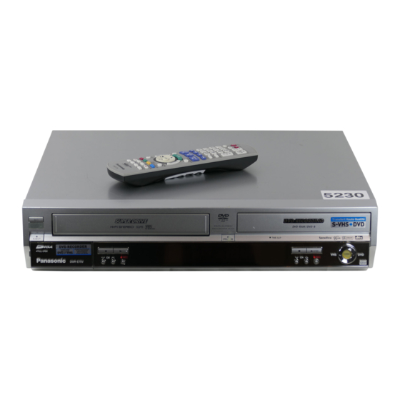
- Page 1 ORDER NO.DSD0403007C1 DVD Video Recorder DMR-E75VP Colour (S).......Silver Type © 2004 Matsushita Electric Industrial CO., Ltd. All rights reserved. Unauthorized copying distribution is a violation of law.
-
Page 2: Casing Parts & Mechanism Section
DMR-E75VP... -
Page 3: Table Of Contents
DMR-E75VP CONTENTS Page Page 1 Safety precautions 15.2. Checking and Repairing of Main P.C.B. 1.1. General guidelines 15.3. Checking and Repairing of Digital P.C.B. 1.2. Caution for fuse replacement 15.4. Checking and Repairing of I/O P.C.B. 2 Prevention of Electrostatic Discharge (ESD) to Electrostatic 15.5. - Page 4 DMR-E75VP 22.8. AVENC/RTSC Section (Digital P.C.B.(2/4)) Schematic 23.2. Main P.C.B. Diagram (EN) 23.3. Digital P.C.B. 22.9. AV Decoder/Main CPU Section (Digital P.C.B.(3/4)) 23.4. I/O P.C.B. Schematic Diagram (MC) 23.5. Front Jack , FL Drive P.C.B. 22.10. Audio I/O Section (Digital P.C.B.(4/4)) Schematic Diagram...
-
Page 5: Safety Precautions
DMR-E75VP 1 Safety precautions 1.1. General guidelines 1. When servicing, observe the original lead dress. If a short circuit is found, replace all parts which have been overheated or damaged by the short circuit. 2. After servicing, see to it that all the protective devices such as insulation barriers, insulation papers shields are properly installed. -
Page 6: Prevention Of Electrostatic Discharge (Esd) To Electrostatic Sensitive (Es) Devices
DMR-E75VP 2 Prevention of Electrostatic Discharge (ESD) to Electrostatic Sensitive (ES) Devices Some semiconductor (solid state) devices can be damaged easily by static electricity. Such components commonly are called Electrostatic Sensitive (ES) Devices. Examples of typical ES devices are integrated circuits and some field-effect transistor-sand semiconductor "chip"... -
Page 7: Precaution Of Laser Diode
DMR-E75VP 3 Precaution of Laser Diode... -
Page 8: How To Replace The Lithium Battery
( As shown in 23.2.3. The Main P.C.B. ) NOTE: The lithium battery is a critical component. ( Type No.: CR2354-1GUF Manufactured by Panasonic. ) It must never be subjected to excessive heat or discharge. It must therefore only be fitted in equipment designed specifically for its use. -
Page 9: Each Buttons
DMR-E75VP 6 Each Buttons... - Page 10 DMR-E75VP...
- Page 11 DMR-E75VP...
-
Page 12: New Features
DMR-E75VP 7 New Features 7.1. Function of Power Circuit (IC11150) 1. General We adopted IC module as the Switching Power Circuit for lower power consumption. IC11150 is constructed with Switching materials and Control IC, and is partial resonance module. We realized Switching Power with high efficiency, low noise and low power consumption. - Page 13 DMR-E75VP Startup Circuit Timing Chart Function of Z/C Terminal When voltage of Z/C reaches 0.25V, Gate signal is output and Drain current starts to flow. Function of F/B terminal F/B signal decides Switching ON width in low voltage controlling. The Switching ON width responds to change of F/B Voltage.
- Page 14 DMR-E75VP IC11150 Block Diagram Signal name Pin No. Name Symbol Zero Current Det. Feed back Drain Drain...
-
Page 15: Disc Cannot Be Ejected By Open/Close Button
DMR-E75VP 8 (DVD) Taking out the Disc from RAM-Drive Unit when the Disc cannot be ejected by OPEN/CLOSE button 8.1. (DVD) Forcible Disc Eject 8.1.1. (DVD) When the power can be turned off. 1. Turn off the power and press [(DVD) STOP], [(DVD) CH UP] keys on the front panel simultaneously for 5 seconds. -
Page 16: Vhs) Removing Cassette Tape Manually
DMR-E75VP 9 (VHS) Removing Cassette 3. Stop unloading just before unloading will be completed as Tape manually shown below, and then the tape becomes slack as shown below. When the cassette tape could not be uninstalled from an 4. Rotate the S-Reel by a small minus screwdriver to remove electrical malfunction, there are 2 ways to remove a cassette the slack tape as shown below. -
Page 17: Vhs) Take Out Cassette Tapemanually After Removing The Mechanism
DMR-E75VP 9.3. (VHS) Take out Cassette 6. Attach Loading Motor and tighten the screw. Tapemanually after removing 7. Set the Position Switch to EJECT POSITION certainly and the mechanism attach the mechanism to chassis as shown below. 1. Disconnect the AC plug, and remove the Top Panel, Front Panel and the Mechanism by referring to "13 Assembling... -
Page 18: Dvd) Service Explorer
DMR-E75VP 10 (DVD) Service Explorer Confirm “RAM-Drive Last Error” in Service Mode Execute Service Mode 1. When the power is off, press [VHS to DVD DUBBING], [OPEN/CLOSE] and [DVD STOP keys simultaneously for 5 seconds. FL Display: *After finishing display “(7). Factor of Drive Error occurring”, press [0] [2] ~[9] [9] keys of the Remote Controller so that 99 memories can be displayed as maximum. - Page 19 DMR-E75VP (5) Error occurring Disc type is displayed for 5 seconds. (6) Disc Maker´s ID is displayed for 5 seconds. Example of Disc Maker´s ID: DVD-R Disc FL Display (Disc Maker´s ID) Disc Maker Country Panasonic Japan Pioneer Japan Mitsubishi Chemical Corporation...
- Page 20 DMR-E75VP Error Occurring Disc State...
-
Page 21: Dvd) Self-Diagnosis And Special Mode Setting
DMR-E75VP 11 (DVD) Self-Diagnosis and Special Mode Setting 11.1. (DVD) Self-Diagnosis Functions Self-Diagnosis Function provides information for errors to service personnel by “Self-Diagnosis Display” when any error has occurred. U59, H** and F** are stored in memory and held. Display on FL will be cancelled when the power is turned off or AC input is turned off during self-diagnosis display is ON. -
Page 22: Dvd) Special Modes Setting
DMR-E75VP 11.2. (DVD) Special Modes Setting Item FL display Key operation Mode name Description Front Key TEST Mode *All the main unit´s parameters (include tuner) Press [VHS to DVD DUBBING], are initialized. [DVD DUBBING] Then VHS Microproccesor is initialized to... - Page 23 DMR-E75VP Aging Contents (Example):...
-
Page 24: Dvd) Service Modes
DMR-E75VP 11.3. (DVD) Service Modes Service mode setting: While the power is off, press [VHS to DVD DUBBING], [OPEN/CLOSE] and [(DVD) STOP] keys simultaneously for five seconds. Item FL display Key operation Mode name Description (Remote controller key) Release Items Item of Service Mode executing is cancelled. - Page 25 DMR-E75VP Item FL display Key operation Mode name Description (Remote controller key) White Picture Output White picture is output as component Output *Initial mode is “Interlace”. Press [1] [1] in service mode. from AV Decoder. *White picture (Saturation rate : 100%)
- Page 26 DMR-E75VP Item FL display Key operation Mode name Description (Remote controller key) I/P Switch Switch Interlace and Progressive in EE mode. Initial mode is Interlace Press [1] [4] in I/P Switch mode. *Initial setting is “Interlace”. *I/P are switched alternately.
- Page 27 DMR-E75VP Item FL display Key operation Mode name Description (Remote controller key) RAM Drive Last Error RAM Drive error code display. 1. Error Number is displayed for 5 Press [4] [2] in service mode. *For details about the drive error code, refer seconds.
- Page 28 DMR-E75VP Item FL display Key operation Mode name Description (Remote controller key) Display the Error History Display the Error History stored on the unit. Display reason of error for 5 Press [6] [5] in service mode. seconds. Then press [0] [1] ~ [1] [9], the past 19 error histories are displayed.
-
Page 29: Vhs) Self-Diagnosis And Special Mode Setting
DMR-E75VP 12 (VHS) Self-Diagnosis and Special Mode Setting 12.1. (VHS) Self-Diagnosis Functions This model has a self-diagnosis and display function. If the VHS section detects trouble during installation or during use, one of the following Error Codes will automatically appear in the display on VHS side. Error Codes are displayed in the form of a single English letter followed by two numbers, as for example "H01". -
Page 30: Vhs) Special Modes Setting
DMR-E75VP 12.2. (VHS) Special Modes Setting Item FL display Key operation Mode name Description Front Key Tracking Center Tape Tracking is adjusted to center No display. During PLAYBACK, press [(VHS) CH FIX position. UP] and [(VHS) CH DOWN] keys simultaneously. -
Page 31: Vhs) Self-Diagnosis History Memory Function
DMR-E75VP Service Contents Contents of Indication on minute Contents of Indication on second Remarks Number Indication for the Real time servo data (4 digits) inner data (Real time) IC6001 Higher rank 1 BYTE of SERVO data Lower rank 1 BYTE of SERVO data... - Page 32 DMR-E75VP 12.4.4. (VHS) Display of Supplementary Data 3 and 4 During displaying the Self-Diagnosis History, press [STOP] key on front panel to change the display. *Example of Display A: Service Mode Number. B: Supplementary Data 3...Mechanism process shifting Number. C: Supplementary Data 4...LM(Loading Motor information) *Display of means that "...
-
Page 33: Vhs) Description Of Self Diagnosis Memory
DMR-E75VP 12.5. (VHS) Description of Self Diagnosis Memory In this Self-Diagnosis Function, in case error has occurred continuously, maximum of the newest 3 error data are memorized. And in order to analyze cause of error, the error number and the supplementary data of mode, mechanism position and so on are memorized. - Page 34 DMR-E75VP Note 2: Explanation of "Tape position" of the Supplementary Data The Tape position Data is the area data of S-reel that is used for judgment of reducing speed in the Main microprocessor IC6001, and as the tape position is moved from the starting edge to the finishing edge, the value becomes smaller.
-
Page 35: Assembling And Disassembling
DMR-E75VP 13 Assembling and Disassembling 13.1. Disassembly Flow Chart The following chart is the procedure for disassembling the casing and inside parts for internal inspection when carrying out the servicing. To assemble the unit, reverse the steps shown in the chart below. -
Page 36: Positions
DMR-E75VP 13.2. P.C.B. Positions 13.3. Cation with inserting cassette tape when disassembling the unit Note1: For description of the disassembling procedure, see the section 13.4. Note2: Video Cassette might not enter when a strong lighting is applied to VHS Mechanism when Video Cassette is inserted. Please... -
Page 37: Top Case
DMR-E75VP 13.4. Top Case 13.5. Front Panel 1. Remove the 4 screws (A) and 3 screws (B). 1. Remove one screw (A). 2. Slide the Top Case for rear direction slightly, and open the 2. Unlock tab (A) and tab (B) simultaneously. -
Page 38: Front Jack P.c.b. & Fl Drive
DMR-E75VP Note: 13.7. Rear Panel & Fan Motor When attaching Front Panel, in order to hook Cassette 1. Remove 5 Screws (A) and Screw (B) and Fan Connector. Door Opener Lever to Cassette Door, push up cassette 2. Unlock 2 Locking Tabs to remove Rear Panel with Fan door in the direction of arrow and insert a front panel. -
Page 39: I/O P.c.b
DMR-E75VP 13.8. I/O P.C.B. At first, disconnect one connector on one side of I/O P.C.B, and pull out the I/O P.C.B. 13.9.1. Caution for attaching VTR Mechanism Unit 1. Because Position SW should be set to "Eject Position", refer to fig.(A) and set the position switch so that the boss and arrow mark come on a straight line. -
Page 40: Main P.c.b
DMR-E75VP 13.10. Main P.C.B. 13.11. DVD-RAM Drive 1. Disconnect 4 Connectors. 1. Remove Screw (A) and Earth Angle. 2. Remove 2 Screws (A), and remove Main P.C.B. 2. Remove 3 Screws (B). 3. Lift up DVD-RAM Drive slightly. 4. Remove wire cable from Wire Clamper (A). -
Page 41: Digital P.c.b
DMR-E75VP 13.12. Digital P.C.B. 1. Remove 4 Screws (A) and DVD Angle. 2. Disconnect FFC. 3. Remove Screw (B). 4. Unlock Clamper (A), pay attention to Connector (A), and pull out Digital P.C.B. to disconnect Connector (A). CAUTION 1: When replacing Digital P.C.B., pay attention to inserting FFC, and be careful to do not touch surface of CSP ICs. -
Page 42: Power & Digital I/F P.c.b
DMR-E75VP 13.13. Power & Digital I/F P.C.B. 1. Remove Front Panel (refer to 13.5.), Rear Panel (refer to 13.7.), DVD-RAM Drive (refer to 13.11.),Digital P.C.B. (refer to 13.12.) and VTR Mechanism (refer to 13.9.). 2. Disconnect 4 Connectors. 3. Install VTR Mechanism (refer to 13.9.). -
Page 43: Service Fixture And Tools
DMR-E75VP 14 Service Fixture and Tools Part Number Description Compatibility RFKZ0125 Extension FFC (Digital P.C.B. - DVD-RAM Drive / 40 Pin) Same as E50 series RFKZ0168 Extension Cable (Power & Digital I/F P.C.B. - FAN / 3 Pin) Same as E50 series RFKZ0169 Extension Cable (RAM Drive - Power &... -
Page 44: Service Positions
DMR-E75VP 15 Service Positions Note: For description of the disassembling procedure, see the section 13. 15.1. Checking and Repairing of Power & Digital I/F P.C.B. -
Page 45: Checking And Repairing Of Main P.c.b
DMR-E75VP 15.2. Checking and Repairing of Main P.C.B. -
Page 46: Checking And Repairing Of Digital P.c.b
DMR-E75VP 15.3. Checking and Repairing of Digital P.C.B. -
Page 47: Checking And Repairing Of I/O P.c.b
DMR-E75VP 15.4. Checking and Repairing of I/O P.C.B. -
Page 48: Checking And Dvd-Ram Drive
DMR-E75VP 15.5. Checking and DVD-RAM Drive... -
Page 49: Dvd) Caution After Parts Replacing Parts
DMR-E75VP 16 (DVD) Caution after parts replacing parts 16.1. (DVD) After replacing the RAM Drive with new one Caution: In this case, all parameters are initialized. 16.2. (DVD) When the unit does not operate normally after replacing the Timer Microprocessor with new one... -
Page 50: Vhs) Caution After Replacing Parts
DMR-E75VP 17 (VHS) Caution after replacing parts PG Shifter Automatic Adjustment and X-VALUE & LINEARITY (P2 and P3 Posts) ADJUSTMENT should be performed after replacing DD Cylinder, VHS Microprocessor or Main P.C.B. 17.1. (VHS) Adjustment Procedures after replacing DD Cylinder, VHS Microprocessor or Main P.C.B. -
Page 51: Adjustment
DMR-E75VP 17.2. (VHS) X-VALUE & LINEARITY (P2 and P3 Posts) ADJUSTMENT l Main symptoms and Adjustment point Envelope Post Name Adjustment Method P2 Post Turn P2 Post counter-clockwise (Approx. 1/2 revolution) P2 Post Turn P2 Post clockwise (Approx. 1/4 revolution) - Page 52 DMR-E75VP...
-
Page 53: Vhs) Caution After Replacing Vhs Microprocessor (Ic6001)
Turn on the power, and confirm items pointed out. Items pointed out should reappear. Insert RAM disc. The Panasonic RAM disc should be recognized. Enter the EE (TU IN / AV IN - AV OUT) mode. No abnormality should be seen in the picture, sound or operation. -
Page 54: Voltage And Waveform Chart
DMR-E75VP 19 Voltage and Waveform Chart Note) · · · · Indicated voltage values are the standard values for the unit measured by the DC electronic circuit tester (high-impedance) with the chassis taken as standard. Therefore, there may exist some errors in the voltage values, depending on the internal impedance of the DC circuit tester. -
Page 55: Main P.c.b
DMR-E75VP Q11200 Q11270 Q31401 Ref No. MODE 11.4 10.4 12.5 12.5 12.5 12.5 12.5 10.5 12.5 PLAY 11.4 10.4 12.5 12.5 12.5 12.5 12.5 10.5 12.5 STOP 11.4 10.4 12.5 12.5 12.5 12.5 12.5 10.5 12.5 Q37512 Ref No. MODE 12.5... - Page 56 DMR-E75VP Ref No. IC3901 IC3903 MODE PLAY STOP IC4301 Ref No. MODE 12.0 12.1 PLAY 12.0 12.1 STOP 12.0 12.1 IC4302 Ref No. MODE 12.1 PLAY 12.1 STOP 12.1 IC4501 Ref No. MODE PLAY STOP IC4501 Ref No. MODE PLAY STOP Ref No.
-
Page 57: I/O P.c.b
DMR-E75VP Q1341 Q1351 Q1352 Q1353 Q1501 Ref No. MODE 12.1 12.8 12.8 PLAY 12.1 12.8 12.8 STOP 12.1 12.9 12.8 Q1502 Q3001 Q3004 Q3701 Q3702 Ref No. MODE PLAY STOP -0.1 Q4001 Q4081 Ref No. Q3903 Q4002 MODE -18.5 -26.6 -18.5... -
Page 58: Fl Drive P.c.b
DMR-E75VP 19.4. FL Drive P.C.B. IC7502 Ref No. MODE STOP -23.3 -20.3 -17.3 -20.2 -26.3 -29.3 -22.7 -29.1 -29.3 -26.2 -29.3 IC7502 Ref No. MODE STOP -23.2 -29.3 -29.3 -19.6 -22.8 -22.8 -29.1 -20.2 -26.3 -23.3 -26.3 -22.8 -20.1 -16.8 -23.1... -
Page 59: Waveform
DMR-E75VP 19.7. Waveform IC6001-18(TW2001) REC IC6001-19 PLAY IC6001-50 REC/PLAY IC6001-52 REC/PLAY IC6001-79 FF/REW 5.0Vp-p (10msec.div.) 5.0Vp-p (5msec.div.) 1.5Vp-p (20usec.div.) 1.5Vp-p (20usec.div.) 5.0Vp-p (1msec.div.) IC6001-86(TL2015) PLAY IC6001-95 REC IC6001-80 FF/REW IC6001-90 REC IC6001-94 REC 0.8Vp-p (0.5msec.div.) 2.4Vp-p (10msec.div.) 5.0Vp-p (1msec.div.) 5.0Vp-p (10msec.div.) 2.4Vp-p (10msec.div.) - Page 60 DMR-E75VP IC11150-2 STOP 0.2Vp-p (5usec.div) T11150-3 STOP T11150-4 STOP T11150-6 STOP T11150-7 STOP T11150-8 STOP 30Vp-p (5usec.div) 300Vp-p (5usec.div) 10Vp-p (2msec.div) 38Vp-p (5usec.div) 32Vp-p (5usec.div) P9001-1 REC/PLAY P9001-2 REC/PLAY P9001-18 REC/PLAY P9001-22 REC/PLAY P9001-26 REC/PLAY 0.8Vp-p (20usec.div) 0.8Vp-p (20usec.div) 0.8Vp-p (20usec.div.) 0.8Vp-p (20usec.div.)
-
Page 61: Abbreviations
DMR-E75VP 20 Abbreviations 20.1. DVD INITIAL/LOGO ABBREVIATIONS ERROR TORQUE CONTROL ERROR TORQUE CONTROL INITIAL/LOGO ABBREVIATIONS REFERENCE A0~UP ADDRESS ENCSEL ENCODER SELECT ACLK AUDIO CLOCK ETMCLK EXTERNAL M CLOCK (81MHz/40.5MHz) AD0~UP ADDRESS BUS ETSCLK EXTERNAL S CLOCK (54MHz) ADATA AUDIO PES PACKET DATA... - Page 62 DMR-E75VP INITIAL/LOGO ABBREVIATIONS INITIAL/LOGO ABBREVIATIONS READ ENABLE VBLANK V BLANKING RFENV RF ENVELOPE COLLECTOR POWER SUPPLY RF PHASE DIFFERENCE OUTPUT VOLTAGE (CD-ROM) REGISTER SELECT VCDCONT VIDEO CD CONTROL (TRACKING RSEL RF POLARITY SELECT BALANCE) RESET DRAIN POWER SUPPLY VOLTAGE RESERVE...
-
Page 63: Vhs
DMR-E75VP 20.2. VHS 4.43 NTSC L 443NT [L] BILINGUAL BILINGUAL L A. COMP BIL [L] AUDIO COMPONENT SIGNAL BILINGUAL H BIL. [H] A. COMPO AUDIO COMPONENT SIGNAL AUDIO DUBBING PAUSE L BILINGUAL L BIL/M1 [L] A. D.P [L] AUDIO DUBBING PAUSE L BS CLOCK A. - Page 64 DMR-E75VP CYL GND CYLINDER GND FULL. E. 12V FULL ERASE 12V DELAIED FM RECORDING H D.F.M. REC [H] GND [A] GND (ANALOG) DELAIED FM RECORDING L D. FM REC [L] GND [TU] GND (TUNER) D. GND DIGITAL GND GND/N. SW. 12V...
- Page 65 DMR-E75VP POWER OFF H LINE IN [R] LINE INPUT (R) P-OFF [H] POWER OFF L LINE OUT [L] LINE OUTPUT (L) P-OFF [L] LINE OUT [R] LINE OUTPUT (R) P. FAIL POWER FAILURE DETECT LP H POWER OFF H LP [H] P.
- Page 66 DMR-E75VP RF OUT RF OUTPUT SYSCON 5V SYSTEM CONTROL 5V RF Y RF LUMINANCE SIGNAL SYSTEM SYSTEM SW RF. Y. IN RF LUMINANCE SIGNAL INPUT T-PHOTO TAKE-UP PHOTO TRANSISTOR TAKE-UP REEL PULSE RF. Y. OUT RF LUMINANCE SIGNAL OUTPUT T-RL. PLS TIMER BUS CLOCK ROTAR.
-
Page 67: Block Diagram
DMR-E75VP 21 Block Diagram 21.1. Power Supply Block Diagram D11110,L11120 D11141 L11121 C11141,C11142 T11150 SW TRANSFORMER AC SOCKET F11101 P11101 TO MAIN P.C.B. (250V2A) SURGE RECTIFIER X SW+15.5V P31902 P6002 SUPPRESSOR SURGE ABSORBER IC11400 (DC/DC CONVERTER) VOUT IC11150 D11270 (SW IC) -
Page 68: Digital I/F Regulator Block Diagram
DMR-E75VP 21.2. Digital I/F Regulator Block Diagram IC31400 Q31401 IC31509 (POWER CONTROL) (FET DRIVE) (REG.D +1.2V) P39702 P9001 D +1.2V IP31400 V IN V OUT DRIVE X SW +13V V IN V OUT IC31510 (REG.D +1.5V) QR31301 P39702 P9001 DRIVE D +1.5V... -
Page 69: Digital I/F Timer Block Diagram
DMR-E75VP 21.3. Digital I/F Timer Block Diagram POWER & DIGITAL I/F P.C.B. FL DRIVE P.C.B. IC37501 DP7501 (DIGITAL I/F & TIMER CPU) TIMER DISPLAY (LPF) AD +5V LP2FSC P31905 P6005 QR7901 FL ON :ON) 32 LP3FSC T7901 (DC/DC LP4FSC CONVERTER) -
Page 70: System Control, Servo & Timer Block Diagram
DMR-E75VP 21.4. System Control, Servo & Timer Block Diagram IC0201 IC6001 MAIN P.C.B. (CAPSTAN MOTOR DRIVE) X SW (SYSTEM CONTROL/SERVO/TIMER) +15.5V P0201 P2571 TL2502 32KHz IN 35 CAPSTAN CAP TL MOTOR X6002 COILS (32KHz) MOTOR DIFFERENTIAL TORQUE P0201 P2571 CURRENT LIMIT... -
Page 71: Audio Block Diagram
DMR-E75VP 21.5. Audio Block Diagram DVD AUDIO SIGNAL AUDIO MAIN SIGNAL PATH IN REC MODE AUDIO MAIN SIGNAL PATH IN PLAYBACK MODE IC7301 IC4501 IC3001 (AUDIO DECODER) (AUDIO PROCESSOR) (AUDIO PROCESSOR) Q4001, IC6001- TU7401 QR4801 Q4002 D.REC U/V TUNER FL4562... -
Page 72: Video Block Diagram
DMR-E75VP 21.6. Video Block Diagram IC3701 (VIDEO I/O PROCESSOR) CPS V OUT VIDEO CPN Y OUT DVD C IN P9001 P39702 P31902 P6002 C OUT DM BIAS 6M LPF S-VIDEO C75 OUT CPN C OUT JK3902 DVD Y IN P9001... - Page 73 DMR-E75VP :DVD VIDEO EE SIGNAL :REC SIGNAL :PB SIGNAL Q3004 IC3001 (AUDIO/VIDEO SIGNAL PROCESSOR) 2MHz TW3001 VIDEO ENVE VTR TU V IN SVHS SQUELCH -6dB -4dB SVHS L1 V IN CLEAR SQUELCH V-AMP -10dB SYNC VIDEO FEED BACK NTSC/PAL COLOUR...
-
Page 74: Digital Block Diagram
DMR-E75VP 21.7. Digital Block Diagram IC3402 IC3408 16bit/256M 32bit/64M SDRAM SDRAM IC3401 IC3404 (VAD CON) (AV ENC / RTSC) ADYOUT4 SDRAM SDRAM YIN4 ADYOUT3 YIN3 ADYOUT2 YIN2 27MHz ADYOUT1 P7402 P9001 V YIN DM YIN1 ADYOUT0 384fs YIN0 ANALOG VIDEO... -
Page 75: Digital Block Ic Pin Terminal Chart
DMR-E75VP 21.8. Digital Block IC Pin Terminal Chart IC Pin Terminal Chart ( TC 1 - TC 6 ) IC Pin Terminal Chart ( TC7 - TC10 ) IC3404 / AVENC&RTSC IC3402 / SDRAM IC3404 / AVENC&RTSC FP3401 (DVD RAM) IC50001 / SDRAM IC6001 / AV DEC&MAIN CPU... - Page 76 DMR-E75VP SA0 - SA25 ADDRESS BUS LINE (TC12, TC14-1, TC15-1, TC17, TC18-1) SD16 - SD31 DATA BUS LINE (TC14-2, TC15-2, TC18-2 ) 14-1 15-1 18-1 14-2 15-2 18-2 IC3404 / AVENC&RTSC IC6701 / GLUE IC6001 / AVDEC&MAIN CPU IC6004 / BUFFER...
-
Page 77: Schematic Diagram
DMR-E75VP 22 Schematic Diagram 22.1. Interconnection Schematic Diagram PS43001 P4501 P6001 X SW5.8V P2571 X SW5.8V AU5V AU5V X SW13V TU7401 CAP R/F CAP R/F AUDIO L1 IN L AUDIO L1 IN L X SW13V U/V TUNER CAP ET CAP ET... - Page 78 DMR-E75VP P39702 P9001 DVD RAM DRIVE P31901 CPNCIN DM CPNCIN DM X SW5.8V V YIN DM V YIN DM X SW5.8V DGND DGND X SW13V DGND DGND X SW13V G/CY IN IECOUT P11101 RGB CPSVIN RGB CPSVIN/EPG TU IN ANA5V...
-
Page 79: Power Supply Section (Power & Digital I/F P.c.b.(1/2))
DMR-E75VP 22.2. Power Supply Section (Power & Digital I/F P.C.B.(1/2)) Schematic Diagram (P) R11408 L11401 22u D1BDR1800001 L11402 10u LB11402 J0JHC0000012 D11400 MA2Q73800L R11409 C11470 C11471 D1BDR1800001 10V1000 10V220 C11405 LB11400 R11410 C11406 1000P R11405 D1BDR1800001 C11408 D11401 MA2J11100L 1000P... -
Page 80: Digital I/F Section (Power & Digital I/F P.c.b.(2/2)) Schematic Diagram (D)
DMR-E75VP 22.3. Digital I/F Section (Power & Digital I/F P.C.B.(2/2)) Schematic Diagram (D) LB31902 J0JHC0000032 < X SW15.5V > X SW15.5V LB31903 J0JHC0000032 < X SW13V > < X SW13V > X SW13V X SW5.8V < X SW5.8V > < X SW5.8V >... - Page 81 DMR-E75VP < X SW15.5V > < X SW15.5V > < X SW13V > < X SW13V > < X SW5.8V > < X SW5.8V > < AD5V > < AD5V > R37533 < REG.ANA5V > R37523 15K C37566 K37503 C37569...
- Page 82 DMR-E75VP AUDIO MAIN SIGNAL PATH IN REC MODE AUDIO MAIN SIGNAL PATH IN PLAYBACK MODE FAN MOTOR < X SW15.5V > DVD VIDEO SIGNAL < X SW13V > Q37512 P37503 2SD0874A0L DVD AUDIO SIGNAL FANDCOUT < X SW5.8V > (FAN MOTOR DRIVE) FANLOCK <...
-
Page 83: Syscon/Servo/Timer Section (Main P.c.b.(1/3)) Schematic Diagram (S)
DMR-E75VP 22.4. Syscon/Servo/Timer Section (Main P.C.B.(1/3)) Schematic Diagram (S) VIDEO MAIN SIGNAL PATH IN REC MODE VIDEO MAIN SIGNAL PATH IN PLAYBACK MODE AUDIO MAIN SIGNAL PATH IN REC MODE AUDIO MAIN SIGNAL PATH IN PLAYBACK MODE TO P31901 < X SW 13V >... - Page 84 DMR-E75VP TO P31903 DVD AUDIO EE SIGNAL DVD VIDEO EE SIGNAL CAPSTAN SERVO SPEED LOOP CAPSTAN SERVO PHASE LOOP CYLINDER SERVO SPEED LOOP CYLINDER SERVO PHASE LOOP POWER AND DIGITAL I/F P.C.B. (DIGITAL I/F SECTION) P6003 AUGND VTR S OUT <...
-
Page 85: Hi-Fi Audio Section (Main P.c.b.(2/3)) Schematic Diagram
C1352 D1351 K7409 R4304 100K 6V22 MAZ4056NHF C7425 0.01 R4302 1K REG.12V < REG.12V > L4501 1.2u A 5V < REG.A 5V > < REG.A 5V > < X SW5.8V > DMR-E75VP Hi-Fi Audio Section (Main P.C.B.(2/3)) Schematic Diagram (A) - Page 86 X SW5.8V > NOTE:DO NOT USE ANY PART NUMBER SHOWN ON THIS SCHEMATIC DIAGRAM FOR DMR-E75VP Hi-Fi Audio Section (Main P.C.B.(2/3)) Schematic Diagram (A) ORDERING.WHEN YOU ORDER A PART,PLEASE REFER TO PARTS LIST. DMR-E75VP Hi-Fi Audio Section (Main P.C.B.(2/3)) Schematic Diagram (A)
-
Page 87: Video Section (Main P.c.b.(3/3)) Schematic Diagram (V)
(D REC :OFF) K3010 R3961 C4083 220u R3037 6V47 R3951 2200 KILLER R3962 D REC A 5V X SW 5.8V X SW5.8V V REG 5V REG.5V ANA 5V ANA 5V UNREG 6V DMR-E75VP Video Section (Main P.C.B.(3/3)) Schematic Diagram (V) - Page 88 R4011 1500 150P R3022 L4001 L3003 C3011 C3012 3300 6V47 < REG.5V > < REG.5V > < ANA 5V > < ANA 5V > DMR-E75VP Video Section (Main P.C.B.(3/3)) Schematic Diagram (V) DMR-E75VP Video Section (Main P.C.B.(3/3)) Schematic Diagram (V)
- Page 89 FOR ORDERRING.THE CORRECT PART NUMBER IS SHOWN IN THE PARTS LIST,AND MAY BE SLIGHTLY DIFFERNT OR AMENDED SINCE THIS DRAWING WAS PREPARED. < REG.5V > L3703 < ANA 5V > DMR-E75VP Video Section (Main P.C.B.(3/3)) Schematic Diagram (V) DMR-E75VP Video Section (Main P.C.B.(3/3)) Schematic Diagram (V)
-
Page 90: Glue Net Section (Digital P.c.b.(1/4)) Schematic Diagram Gn)
DMR-E75VP 22.7. Glue Net Section (Digital P.C.B.(1/4)) Schematic Diagram (GN) GN:Glue Net Section(Page: TO P39702 EN:AV Encoder/RTSC Section(Page: POWER & DIGITAL I/F P.C.B. (DIGITAL I/F SEC.) MC:AV Decoder/Main CPU Section(Page: P9001 D1.2V D1.2V AI:Audio I/O Section(Page: X SW 5.8V DGND D1.2V... -
Page 91: Glue Net Section (Digital P.c.b.(1/4)) Schematic Diagram
DMR-E75VP EEDATA EEDATA EEBCK EEBCK EELRCK EELRCK ADBCK ADBCK ADLRCK ADLRCK ADDATA ADDATA ENCBCK ENCBCK ENCLRCK < D3.3V > < D3.3V > ENCLRCK ENCDATA ENCDATA FL6701 FL6702 F1H0J4740004 R6726 F1H0J4740004 RX6733 XATRESET 47X4 XRSTENC ACLKSEL X1DA LP AMUTE XADC PD... -
Page 92: Diagram (En)
22X4 FL3412 DQM0 D F1H0J4740004 R3447 6800 XCS0 D R3448 XRAS D R3450 100K 5600 XCAS D R3414 C3441 C3440 R3449 ACLKSEL 6V100 6800 X3401 H0J270500069 ENCLRCK C3407 C3408 R3451 ENCDATA ENCBCK DMR-E75VP AVENC/RTSC Section (Digital P.C.B.(2/4)) Schematic Diagram (EN) - Page 93 R3443 0 PCKO FL3419 AGND BCKIO F1H0J4740004 R3444 0 FL3418 F1H0J4740004 FL3420 < D1.5V > F1H0J4740004 < D3.3V > < D3.3V > R3430 22 R3421 DMR-E75VP AVENC/RTSC Section (Digital P.C.B.(2/4)) Schematic Diagram (EN) DMR-E75VP AVENC/RTSC Section (Digital P.C.B.(2/4)) Schematic Diagram (EN)
-
Page 94: Dmr-E75Vp
NOTE:DO NOT USE THE PART NUMBER SHOWN ON THIS DRAWING FOR ORDERING. THE CORRECT PART NUMBER IS SHOWN IN THE PARTS LIST, AND MAY BE Schematic Diagram (EN) DMR-E75VP AVENC/RTSC Section (Digital P.C.B.(2/4)) Schematic Diagram (EN) SLIGHTLY DIFFERNT OR AMENDED SINCE THIS DRAWING WAS PREPARED. -
Page 95: Av Decoder/Main Cpu Section (Digital P.c.b.(3/4))
J0JHC0000032 F1H0J4740004 RX6033 3.3Kx4 RX6026 33x4 < D1.2V > FL6010 F1H0J4740004 < ANA3.3V > R6001 RX6034 3.3Kx4 RX6001 10Kx4 FL6012 F1H0J4740004 < D1.2V > XMWE3 XMWE2 < D3.3V > XMRE SDCLK DMR-E75VP AVDEC/Main CPU Section (Digital P.C.B.(3/4)) Schematic Diagram (MC) - Page 96 < D3.3V > AVDEC/Main CPU Section (Digital P.C.B.(3/4)) NOTE:DO NOT USE ANY PART NUMBER SHOWN ON THIS SCHEMATIC DIAGRAM FOR Schematic Diagram (MC) ORDERING.WHEN YOU ORDER A PART,PLEASE REFER TO PARTS LIST. DMR-E75VP AVDEC/Main CPU Section (Digital P.C.B.(3/4)) Schematic Diagram (MC)
-
Page 97: Audio I/O Section (Digital P.c.b.(4/4)) Schematic Diagram (Ai)
DMR-E75VP 22.10. Audio I/O Section (Digital P.C.B.(4/4)) Schematic Diagram (AI) LB4401 J0JGC0000020 D3.3V R4426 X1DA LP R4427 DEC SCK R4428 DEC SDTO R4403 R4402 XDMUTE 768FS1 R4425 5600 XRESET C4406 D4401 MA3Z142K0LG C4403 C4402 16V10 OUTY IC4403 C0JBAD000107 IC4402 (XD MUTE OUT) -
Page 98: A/V I/O Schematic Diagram
DMR-E75VP 22.11. A/V I/O Schematic Diagram VIDEO MAIN SIGNAL PATH IN REC MODE AUDIO MAIN SIGNAL PATH IN REC MODE DVD AUDIO SIGNAL VIDEO MAIN SIGNAL PATH IN PLAYBACK MODE AUDIO MAIN SIGNAL PATH IN PLAYBACK MODE TO P4501 MAIN P.C.B. -
Page 99: Fl Drive Schematic Diagram
DMR-E75VP 22.12. FL Drive Schematic Diagram TIMER DISPLAY DP7501 A2BB00000133 R7510 LB7502 SEG11 SEG27 TO PP31904 SEG10 SEG28 POWER AND DIGITAL I/F P.C.B. (DIGITAL I/F SECTION) PP7501 SEG09 SEG29 DVD KEY IN1 SEG08 SEG30 S7501 DVD KEY IN2 EVQ11G04M DVD KEY IN3... -
Page 100: Front Jack Schematic Diagram
DMR-E75VP 22.13. Front Jack Schematic Diagram VIDEO MAIN SIGNAL PATH IN REC MODE AUDIO MAIN SIGNAL PATH IN REC MODE IC7801 R7802 R7803 R7804 R7806 PNA4618M12VT 1800 3300 4700 6800 (REMOTE CTL.RECEIVER) S7806 S7805 S7803 S7802 S7801 EVQ11G07K EVQ11G07K EVQ11G07K... -
Page 101: Print Circuit Board
DMR-E75VP 23 Print Circuit Board 23.1. Power & Digital I/F P.C.B Power & Digital I/F P.C.B. DMR-E75VP Power & Digital I/F P.C.B. (VEP09133A) - Page 102 DMR-E75VP 23.1.1. Power & Digital I/F P.C.B. Address Information Power&Digital I/F P.C.B. Integrated Circuit D31401 C11142 C33734 R11408 R37559 IC11150 D37509 C11150 C33735 R11409 R37561 IC11200 D37510 C11151 C33738 R11410 R37562 IC11400 D37512 C11152 C33740 R11411 R37569 Crystal Osillator IC11500...
-
Page 103: Main
DMR-E75VP 23.2. Main P.C.B. 23.2.1. Main P.C.B. (1/4 Section) (FRONT) (REAR) Location Map DMR-E75VP Main P.C.B. (VEP06F77BT) (1/4 Section) - Page 104 DMR-E75VP 23.2.2. Main P.C.B. (2/4 Section) (FRONT) (REAR) Location Map DMR-E75VP Main P.C.B. (VEP06F77BT) (2/4 Section)
- Page 105 DMR-E75VP 23.2.3. Main P.C.B. (3/4 Section) Main P.C.B. (FRONT) (REAR) Location Map DMR-E75VP Main P.C.B. (VEP06F77BT) (3/4 Section)
- Page 106 DMR-E75VP 23.2.4. Main P.C.B. (4/4 Section) (FRONT) (REAR) Location Map DMR-E75VP Main P.C.B. (VEP06F77BT) (4/4 Section)
- Page 107 DMR-E75VP 23.2.5. Main P.C.B. Address Information Main P.C.B. Integrated Circuit Connector LB3913 C3040 C4304 C7312 R3710 R4520 IC1511 JK3901 LB3914 C3041 C4305 C7313 R3711 R4521 IC1512 JK3902 LB3915 C3044 C4306 C7314 R3712 R4522 IC2501 JK3904 LB3916 C3045 C4307 C7315 R3714...
-
Page 108: Digital
DMR-E75VP 23.3. Digital P.C.B. 23.3.1. Digital P.C.B. (Component Side) Digital P.C.B. OVER VIEW DMR-E75VP (Component Side) DIGITAL P.C.B. (Component Side) (REP3717G) - Page 109 DMR-E75VP 23.3.2. Digital P.C.B. (Foil Side) Digital P.C.B. OVER VIEW DMR-E75VP (Foil Side) Digital P.C.B. (Foil Side) (REP3717G)
- Page 110 DMR-E75VP 23.3.3. Digital P.C.B. Address Information Digital P.C.B. Integrated Circuit CKC93 F CKG23 C CL6715 F FL3431 C C4416 F R4426 F R50006 F RX6014 IC3401 C CKC94 F CKG25 C CL6716 F FL3433 C C4417 F R4427 F R50007...
-
Page 111: I/O P.c.b
DMR-E75VP 23.4. I/O P.C.B. I/O P.C.B. Integrated Circuit C43922 C44019 C44051 R43980 R44029 IC43904 C43971 C44022 C44052 R43981 R44031 IC43905 C43973 C44023 Resistor R44005 R44032 IC44001 C43974 C44024 R43917 R44006 R44039 IC44004 C43975 C44025 R43918 R44011 R44042 IC44005 C43976 C44026... -
Page 112: Front Jack , Fl Drive P.c.b
DMR-E75VP 23.5. Front Jack , FL Drive P.C.B. Front Jack P.C.B. FL Drive P.C.B. DMR-E75VP Front Jack P.C.B. (VEP04868B) FL Drive P.C.B. (VEP07A74B) -
Page 113: Exploded Views
DMR-E75VP 24 Exploded Views 24.1. Casing Parts & Mechanism Section 1... - Page 114 DMR-E75VP 24.2. Casing Parts & Mechanism Section 2...
-
Page 115: Vhs Mechanism Section
DMR-E75VP 24.3. VHS Mechanism Section... -
Page 116: Packing & Accessories Section
DMR-E75VP 24.4. Packing & Accessories Section... -
Page 117: Replacement Parts List
DMR-E75VP 25 Replacement Parts List Notes: Ref. Part No. Part Name & Remarks Description *Important safety notice: 34-1 VGL1100 PANEL LIGHT Components identified mark have special 34-2 VGU9602 POWER BUTTON 34-3 VGU9603 EJECT BUTTON(DVD) characteristics important for safety. 34-4 VKF3878... - Page 118 DMR-E75VP Ref. Part No. Part Name & Remarks Ref. Part No. Part Name & Remarks Description Description XTV26+8FR SCREW C3012 ECEA0JKA470 6.3V 47U VHD1095 SCREW C3014 ECJ1XB1C104K 16V 0.1U ECJ1VB1C104K VHD1117 SCREW C3015 ECJ1VB0J105K 6.3V 1U VMX2208 WASHER C3017 ECJ1XB1C104K 16V 0.1U...
- Page 119 DMR-E75VP Ref. Part No. Part Name & Remarks Ref. Part No. Part Name & Remarks Description Description C3926 ECJ1XB1C104K 16V 0.1U ECJ1VB1C104K C6014 ECJ1VB1H102K 50V 1000P C3927,2 ECJ1VB0J105K 6.3V 1U C6015 ECJ1VB1C333K 16V 0.033U C6016 ECJ1VB1H102K 50V 1000P C3945 ECJ1XB1C104K 16V 0.1U...
- Page 120 DMR-E75VP Ref. Part No. Part Name & Remarks Ref. Part No. Part Name & Remarks Description Description D7902 B0AAGM000003 DIODE B0HAGM000001 LB7408 ERJ3GEY0R00V 1/10W 0 D7903 B0JAME000025 DIODE LB7410 J0JHC0000032 COIL D7904,0 MA2C18500E DIODE LB7411 ERJ3GEY0R00V 1/10W 0 LB7901 J0JKB0000028...
- Page 121 DMR-E75VP Ref. Part No. Part Name & Remarks Ref. Part No. Part Name & Remarks Description Description R2503 ERDS2FJ182 1/4W 1.8K R4008 ERJ3GEYJ334V 1/10W 330K R2514- ERJ3GEYJ221V 1/10W 220 R4009 ERJ3GEYJ2R2V 1/10W 2.2 D0GB2R2JA002 R4011 ERJ3GEYD153V 1/10W 15K D0HB153ZA002 R2520...
- Page 122 DMR-E75VP Ref. Part No. Part Name & Remarks Ref. Part No. Part Name & Remarks Description Description R7307,0 ERJ3GEYJ331V 1/10W 330U C3433 ECJ0EB1A104K 10V 0.1U C3435,3 ECJ0EB1A104K 10V 0.1U R7403 ERJ3GEYJ222V 1/10W 2.2K D0GB222JA002 R7404 ERJ3GEYJ681V 1/10W 680 D0GB681JA002 C3440 EEEHB0J101P 6.3V 100P...
- Page 123 DMR-E75VP Ref. Part No. Part Name & Remarks Ref. Part No. Part Name & Remarks Description Description IC6001 MN2DS0011-HR R3467 ERJ2GEJ562X 1/16W 5.6K IC6002 C0EBE0000130 R3468 ERJ2GEJ103 1/16W 10K IC6003 C3CBLD000088 R3470 ERJ2GEJ103 1/16W 10K IC6004 74LVC244APWL C0JBAZ001466 R3471 ERJ2GEJ330X...
- Page 124 DMR-E75VP Ref. Part No. Part Name & Remarks Ref. Part No. Part Name & Remarks Description Description R50003 ERJ2GEJ220X 1/16W 22 ERJ2RMJ220X RX50001 D1H84704A024 RESISTOR-RESISTOR R50004 ERJ2GE0R00X 1/16W 0 R50005 ERJ2GEJ330X 1/16W 33 X3401 H0J270500069 CRYSTAL OSCILLATOR R50006, ERJ2GEJ470 1/16W 47...
- Page 125 DMR-E75VP Ref. Part No. Part Name & Remarks Ref. Part No. Part Name & Remarks Description Description R44017, ERJ3GEY0R00V 1/10W 0 C31416 ECJ2VB1H472K 25V 4700P C31513 ECJ1VB1A105K 10V 1U F1H1A105A028 R44024, ERJ3GEYJ101 1/10W 100 D0GB101JA002 C31514 ECJ1VB0J105K 6.3V 1U C31515 ECJ1XB1C104K 16V 0.1U...
- Page 126 DMR-E75VP Ref. Part No. Part Name & Remarks Ref. Part No. Part Name & Remarks Description Description D31400, MA2Q73800L DIODE P37503 K1KA03A00173 CONNECTOR(3P) P39702 K1KA88A00003 CONNECTOR(88P) D37509 B0JACE000001 DIODE D37512 VLQ0599J680 COIL 68UH G0C680JA0026 PP31903 K1KB08B00043 CONNECTOR(8P) PP31904 K1KB10B00045 CONNECTOR(FEMALE)1...
- Page 127 DMR-E75VP Ref. Part No. Part Name & Remarks Ref. Part No. Part Name & Remarks Description Description R31507 ERJ3RED330 1/16W 33 W316 ERJ6GEY0R00V 1/8W 0 R31508 ERJ3RBD201 1/16W 200 W317-21 ERJ3GEY0R00V 1/10W 0 R31509 ERJ3RBD102V 1/16W 1K W322 ERJ6GEY0R00V 1/8W 0...
- Page 128 DMR-E75VP Ref. Part No. Part Name & Remarks Description n n n n VEP04868B (FRONT JACK P.C.B.) C4801 ECJ1VF1H103Z 50V 0.01U C4802 ECJ1VF1C104Z 16V 0.1U C4803,0 ECJ1VC1H101J 50V 100P C4805,0 ECJ1VB1H102K 50V 1000P C7801 ECJ1VF1C104Z 16V 0.1U IC7801 PNA4618M12VT JK4801...
Need help?
Do you have a question about the DMR-E75VP and is the answer not in the manual?
Questions and answers