
Related Manuals for Hanyoung NP100


Summary of Contents for Hanyoung NP100
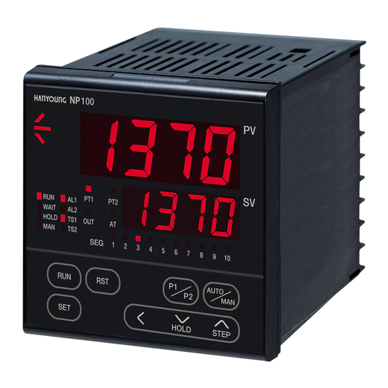
- Page 1 NP100 HANYOUNG Thank you for the purchase of product. Please read this manual carefully.
- Page 3 NP100 Before you use, read safety precautions carefully, and use this product properly. The precautions described in this manual contains important contents related with safety; therefore, please follow the instructions accordingly. The precautions are composed of DANGER, WARNING and CAUTION.
- Page 4 10. Do not use this product at any place with possible thermal accumulation due to direct sunlight or heat radiation. 11. Install this product at place under 2,000m in altitude. 12. Attach the bractets(2pcs) on the fixed halls and tighten with a screwdriver. Fixing torque is about 14.7 N cm (1.5 kg cm) 13.
- Page 5 NP100 Summary Program temperature controller is consisted of three types of modes: operation indicator mode, engineering mode, and program mode. Operation indicator mode is displayed when the power is on and it indicates process value and set value, process value and output volume, and remaining time of the corresponding segment when in operation.
- Page 6 Number Model Function Programmable Controller (96 X 96 mm) NP100- None Time signal 2 points Option RS 485/422 Time signal 2 points +RS 485/422 Caution Wiring Main power must be off before wiring Caution Operate after disconnecting the main power and confirming the...
- Page 7 NP100 Caution Measurement Input Wiring - When wiring the input line, cut off the controller and the external power. - Be careful with polarity and wire the input signal at some interval from power circuit and ground connection circuit. - Use shielded input cable when wiring and earth the shield 1 point.
- Page 8 Function description 6-1. The function of individual LED Function LED display display lamp Lights during the ascending section of the segment. display lamp Lights during the soak section of the segment. display lamp Lights during the descending section of the segment. PT1 display lamp Lights during the pattern 1.
- Page 9 NP100 6-2. Function of control key Caution - press the key firmly with your finger - Do not press the key with any sharpened thing. It could cause key malfunction Operate the current pattern number. Input the parameter setup value Use when moving the parameter Press 2.5 seconds or longer to alternate the operation indicator...
- Page 10 6-3. Function of 4 digits LED 1. Digital Formation 1Digit 2. Possible range of maximum indication using the button. 3. Rounding Up & Off of Digits Rounding Up When it becomes “9” in any digit besides the 4th digit (4D), it will be rounded up to the next digit when the button is pressed continuously.
- Page 11 NP100 Caution Preparation must be carried out in engineering mode when operating the controller. There are setup mode for input and output functions and setup mode for Power control function in engineering mode but must start with the setup of the (ON) input and output functions.
- Page 12 Caution Mode Setup Mode setup is recommended after completing the Program operation since the set value varies in accordance with the setup of the specific parameter. Each parameter may not be indicated in accordance with the selection of form, addendums, control type and varieties of the control system.
- Page 13 NP100 Caution Program mode is recommended after completing the engineering mode since the set value changes and initializes in accordance with the changes in specific engineering mode. Some modes are not represented in accordance with the forms, choices, and control type of the controller.
- Page 14 Model NP 100 program temperature controller is divided into operation indicator mode and program mode and this program mode is further divided into engineering group and program group. Operation indicator mode is displayed when the power is ON and it indicates process Operation value and set value, process value and volume of output, and remaining time of the Indicator Mode...
- Page 15 Burn-out OFF , UP ,DOWN 1) Selection of Input Type: NP100 Program Temperature Controller supports universal input and can be conveniently used by selecting and setting up the input signal symbol of the Input Type Range List. This list includes the application input sensor and input types in accordance with voltage among the total of 18 types of input such as 12 types of thermocouple input (13 types of range), 2 types of R.
- Page 16 8-1-2. Display Signal Item Setup range Initial value condition Setup below parameters. Output group ON / OFF, Output type SSR, SCR, Always Relay selection Relay REV : heating Heating / Cooling Always Heating DIR : cooling control selection 1~1000 sec. Heating cycle time 30 sec.
- Page 17 NP100 8-1-3. Communication Setup Group Caution! PC-LINK Communication / LADER Communication Wiring - Must disconnect the controller and the external power source when connecting to the communication terminal due to the danger of electric shock. - Connect the termination resistor (220 1/4W) at the end or master located at the both ends of the communication equipment.
- Page 18 Display Signal Item Setup range Initial value condition Retransmission Setup below items. setup group Retransmission Always PV, SV, MV(output volume), SPS output selection Max. T.C, R.T.D : FR-H~FR-L RET=PV T.C,RTD : FR-H Retransmission mV,V : SL-H~SL-L MV,SV mV, V : SL-H output (RET.H >...
- Page 19 NP100 Display Signal Setup range condition Initial value Item Alarm setup Setup below items. group OFF / 1~22 Alarm 1 selection Refer to “Alarm type and code” Option Alarm 2 selection (31, 32 page) Dead band of Alarm 1 Option 0.5 %...
- Page 20 8-1-6. Control Setup Group Display Setup range Signal Item Initial value condition Control setup Setup below items. group Except Fuzzy function OFF/ON ON / OFF selection HH.MM (00 Time unit selection HH.MM Always MM.SS (00 Wait zone setup OFF/0~max. range Always OFF / 0.01~99.59 Wait time setup...
- Page 21 NP100 8-1-7. PID Setup Group Display Signal Setup range Initial value Item condition PID setup group Setup below items. P.I.D Anti Reset wind up Auto / 50.0~200.0 % Auto control PID indication group OFF / P1Gr ~P4Gr Always P.I.D n. Proportion 0.1~999.9 %...
- Page 22 8-1-8. Auto Tuning Setup Group Signal Setup range Display condition Initial value Item Auto tuning Setup below items. Please select 1 at “ the AT operation setup group selectin” to run. Except STD:Standard AT Auto tuning type RUN& ON/OFF LOW:Low PV AT(*1) AT operation Except OFF/1~4...
- Page 23 NP100 After “finishing the setup of the engineering group, go into the program mode by pressing on “Group mode”. Also, on operation mode condition (initial mode when power is ON), engineering group will be indicated when pressing for 2.5 seconds, and program mode...
- Page 24 8-2-1. Setup Group for Program Repeat Frequency Setup group for program repeat frequency is indicated if the system is operated as follow when power is ON. 2.5 sec Power Display Signal Setup range Item Initial value condition Setup group for It sets up the repeat frequency and set up items.
- Page 25 1) Selection of Pattern Number : NP100 temperature controller can set up pattern 1, and pattern 2. Select “pattern 1” to operate in the setup item of pattern number selection. (Pattern refers to one setup program.) 2) Selection of segment number : It is designed to set up to 10 segments for each pattern.
- Page 26 3) Setup of Start Set Value : In the program temperature controller, start temperature value can be set up. It could either start from the current temperature in the beginning of the first operation of the system or can even start from the set value in the start set value.
- Page 27 NP100 9-1. Input Input channel number 1 channel Thermocouple, R.T.D(pt), Direct voltage Input type Thermocouple, R.T.D : changeable within range Input range Direct voltage : Variable max. voltage & min. voltage within range Sampling time 250 ms Below decimal point of measurement range...
- Page 28 9-2. Control output Contact capacity : 240 V AC 3 A, 30 V DC 3 A (resistive load) Contact : 1C Output operation : P.I.D control, ON / OFF Proportional cycle : 1 ~ 1000 sec. Relay Output limit : 0.0 ~ 100.0 % range, higher limit(OL-H) or lower limit(OL-L) contact output selectable (valid when AT) ON/OFF hysteresis : 0 ~ 100 %...
- Page 29 NP100 9-5. Communication Interface Standard EIA RS485 Communication address 31, 1~99 setting available Communication method 2 wire half duplex Synchronization Start-stop synchronous mode Communication sequence None Communication distance 1.2Km max. Communication speed 600, 1200, 2400, 4800, 9600 BPS Start bit...
- Page 30 9-9. Power Supply 100 - 240 V AC, 50 - 60 Hz Rated voltage 10 % of rated voltage Tolerable voltage regulation MAX 10 VA(6.0 W max) Power consumption 9-10. Insulation Resistance Primary terminal Secondary terminal MIN. 500 V DC 20 M MIN.
- Page 31 NP100 9-13. Function -100.0 ~ 100.0 % for measuring input range Bias Valid setting a correction value. Measuring According to setup of SL-H, SL-L of measuring range, Scaling Input scaling is available. Filter OFF, 1 ~ 120 sec. Pattern 2 Patterns...
- Page 32 9-14. Alarm Type 1) Output Name Code ON condition OFF condition High absolute alarm 1(11) ALM HYS PV ALM Low absolute alarm 2(12) PV ALM ALM+HYS High deviation alarm 3(13) DEV ALM ALM HYS Low deviation alarm 4(14) ALM+HYS 5(15) ALM HYS High deviation alarm(inverted) DEV ALM...
- Page 33 NP100 (Notice) : Display lamp will be ON when output OFF in inverted type. : Set point , : Mins Alarm set pooint : Alarm set point ) Hysteresis Code Alarm type Function High absolute alarm Low absolute alarm High deviation alarm...
- Page 34 FND display in English Alphabet Alphabet Number None...
- Page 35 NP100 Input type High limit range Low limit range High limit scale Low limit scale 8-1-1 Input setup group Output type Cycle time hysteresis Preset output Max. output Min. output 8-1-2 Output setup group Pattern ending 8-1-5 Alarm dead band...
- Page 36 #1381-3, Juan-dong, Nam-gu, Incheon, Korea TEL:(82-32) 876-4697 FAX:(82-32) 876-4696 http://www.hyelec.co.kr E-mail: mkt@hyelec.co.kr VERSION 1.0...
Need help?
Do you have a question about the NP100 and is the answer not in the manual?
Questions and answers