Table of Contents
Advertisement
Quick Links
Operating Manual
STX Advanced Series
CCD Cameras
SBIG Imaging Systems
A Division of Diffraction Limited.
59 Grenfell Crescent, Unit B, Ottawa, ON Canada, k2G 0G3
Tel: 613.225.2732 | Fax: 225.225.9688| E-mail: tpuckett@sbig.com |
www.sbig.com
© 2016 Diffraction Limited. All rights reserved. The SBIG logo are trademarks of Diffraction Limited,
All other trademarks, service marks and tradenames appearing in this brochure are the property of
their respective owners.
Advertisement
Table of Contents

Related Manuals for SBIG STX Series


Summary of Contents for SBIG STX Series
- Page 1 Tel: 613.225.2732 | Fax: 225.225.9688| E-mail: tpuckett@sbig.com | www.sbig.com © 2016 Diffraction Limited. All rights reserved. The SBIG logo are trademarks of Diffraction Limited, All other trademarks, service marks and tradenames appearing in this brochure are the property of their respective owners.
- Page 2 Consult the dealer or an experienced radio/TV technician for help. Shielded I/O cables must be used when operating this equipment. You are also warned, that any changes to this certified device will void your legal right to operate it. OPERATION Manual for STX Series Cameras Revision 1.3 Dec 2016 CAUTION: Never “hot plug”...
-
Page 3: Table Of Contents
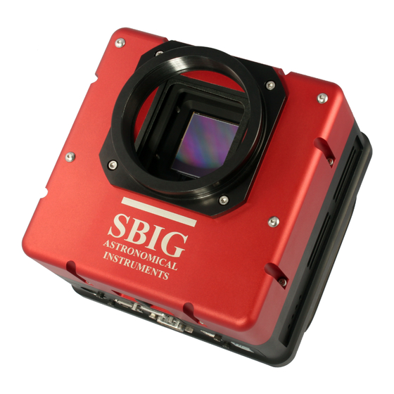
1.16. Camera Field of View .........................18 1.17. Focal Length, Resolution and Field of View................19 2.0. CAMERA SOFTWARE ............................20 2.1 Installing Software .........................20 Installing CCDOps ........................20 Installing the SBIG Drivers....................20 Linking the Drivers .......................21 2.2. Using the Camera..........................22 Establishing a Link with CCDOps ..................22 Camera Setup.........................22 Taking Sample Dark Frames....................22... - Page 4 9 microns. The sensor measures almost 37mm square. The built-in tracking CCD is a Kodak KAI-340S with 640 x 480 pixels at 7.4 microns. The STX series has superior cooling to -50 degrees C below ambient with air only. Water-cooling is also possible.
-
Page 5: Camera Hardware
It is always a good idea to check over your new camera to make sure that you have received all necessary parts and standard accessories. Each STX Series camera is packed in a deluxe custom carrying case. This case contains all the items necessary to operate your camera. -
Page 6: Standard Items
Due to the large size of some CCDs used in the STX series cameras, a 2” nosepiece is too small to use without vignetting the image. Rack handles are also attached to the camera body at the factory. -
Page 7: Optional Items
The STX Guider is directly compatible with the AO-X adaptive optics unit. AO-X The SBIG AO-X is a large aperture AO designed to be compatible with all STX and STXL series cameras, including the STX-16803, STXL-16200, STXL-11000 and STXL-6303. The AO-X requies minimal backfocus while offering a large 3″... -
Page 8: Parts And Assembly
Nikon and Canon Lens Adapters Adapter allows the use of Canon or Nikon 35mm camera lenses on Research Series cameras for wide field imaging. 1.3. Parts and Assembly The black anodized portion of the camera body contains the CCD chamber, electronics, desiccant plug, gas purge valve, heat exchanger, fan and a power supply for 12VDC operation in the field. -
Page 9: Connectors
1.4. Connectors [A] Tracking CCD Focus Adjustment The built-in tracking CCD is set at the factory to be par focal with the imaging CCD assuming a flat field. However, some optical designs produce enough curvature of field to cause star images to be out of focus at the location of the tracking CCD. In this case you may wish to adjust the focus of the tracking CCD. -
Page 10: [D] Scope Port
See Section 1.6 for more information. [E] I2C-AUX Port This port is for attachment of accessories: SBIG filter wheels, Adaptive Optics, etc. Accessories designed to use this port do not require separate power supplies or control cables running to the computer. -
Page 11: Attaching The Camera To A Telescope
The Remote Guiding Head is an opt ional accessory for all models of the STX Series cameras. When attached to the main camera body, the Remote Guiding Head can perform of the functions of the guiding CCD that is built into the camera. -
Page 12: Connecting Water Hoses
1.8. Connecting water hoses STX Series cameras are equipped with a heat exchanger that allows water circulation if conditions require additional coolin of the CCD. The cameras may be operated with or without water circulation. No special steps are necessary to use wate circulation other than connection of a water supply. -
Page 13: Opening The Front Cover - Regenerating The Desiccant Plug
Powered USB extenders. Powered extenders such as the Icron Ranger (www.icron.com) are also commonly available. These extenders require power at one end of the cable (either end) and will let you operate the camera (or any USB device) up to 100 meters from the computer. 1.10. -
Page 14: Gas Purging
1.11. Gas Purging Purging the CCD chamber with an inert gas such as Argon can provide a quick dry air chamber and cooling performance may be slightly improved. However, this procedure is generally unnecessary. The gas purge port is therefore included as a convenience, but not a necessity. You should only consider purging the chamber if it is absolutely necessary. -
Page 15: Opening The Back Cover - Changing The Fuse
1.13. Opening the Back Cover - Changing the Fuse STX cameras have a built-in voltage regulation that lets you run the camera directly from any unregulated 12VDC source such as car battery. The input to this supply is protected with a fuse located inside the rear of the camera. - Page 16 you must carefully pry this connector loose and lift the digital board away from the camera. Care should be taken not to pull too strongly on the digital board far from the connector as this could bend the board and cause cracks in the delicate traces. Once the digital board is removed locate the jumper pins just next to the row of five LEDs that show through holes in the side of the camera body.
-
Page 17: Camera Resolution
1.15. Camera Resolution Resolution comes in two flavors these days. In the commercial world of digital devices, the word resolution is often used synonymously with the number of pixels used in a device. You are used to seeing ads for scanners with a "resolution" of 2,000 x 3,000 pixels, etc. Computer monitors have various "resolution"... -
Page 18: Camera Field Of View
arcseconds per pixel. Also note that cameras with smaller pixels may be binned 2x2 or 3x3 to create larger pixels and expand the useful range of the camera. For example, an STX-16000 with 7.4 micron pixels can be binned 2x2 to give 14.8 micron pixels. The overall field of view of the CCD does not change however, and a camera with larger pixels and a larger field of view might be preferable if it will not be used on shorter focal length instruments. -
Page 19: Focal Length, Resolution And Field Of View
36.8 = 4,979 divided by 30 = 166 arcminutes. The table above shows the calculated field of view in arcminutes for each of the several large format CCDs at various focal lengths. Keep in mind however that when you vary the CCD field of view you are also varying the field of view for each pixel and are therefore also affecting the resolution of your system. -
Page 20: Camera Software
WINDOWS Installing the SBIG Drivers SBIG Cameras require Drivers to be installed in Windows or Mac before you can communicate with them. Our Driver Checker program downloads the latest Drivers from our website and Installs them on your computer. Follow the instructions below to install the SBIG Drivers for your camera: •... -
Page 21: Linking The Drivers
Select Install the software automatically then click Next. • Follow the onscreen instructions to complete linking the drivers to your camera. At this point you could open the Device Manager and verify that you should see an entry for the SBIG Camera. -
Page 22: Using The Camera
In order to control your Camera, CCDOps you must first establish a communications link with the camera as described below: • In the Windows Start menu navigate to the SBIG folder then select the CCDOps icon to launch CCDOps. • Under CCDOps’ Misc menu select the Graphics/Comm Setup command. -
Page 23: Further Investigations
IP address. Making the Autoguiding Connection Like all SBIG cameras, the STX has an Autoguider port that can be connected to your Telescope. Use the supplied 6-pin phone-jack based Autoguider Cable to connect the STX to your Telescope. -
Page 24: Third Party Software
Parallel and USB based cameras. It displays the images and allows saving them in SBIG and FITS formats. In addition you can open images saved in SBIG Format. We offer this as a starting point for the adventurous. -
Page 25: Appendix A - Adjustments And Maintenance
Appendix A – Adjustments and Maintenance This section describes the various adjustments and maintenance issues with the STX. Firmware Updates The STX was designed to allow updating its Firmware (internal software) in the field. Do not update your firmware unless instructed by support staff. Firmware Type Purpose Firmware for the embedded USB processor. -
Page 26: Cleaning The Ccd And The Window
Cleaning the CCD and the Window The design of SBIG cameras allows for cleaning of the CCD. The optical heads are not evacuated and are quite easy to open and clean. When opening the CCD chamber, one should be very careful not to damage the structures contained inside. To open the CCD Chamber, remove the six screws that hold the 5 inch front cover in place. -
Page 27: Appendix B - Capturing A Good Flat Field
Appendix B - Capturing a Good Flat Field This appendix describes how to take a simple flat field. A good flat field is essential for displaying features little brighter than the sky background. The flat field corrects for pixel non-uniformity, vignetting, dust spots (affectionately called dust doughnuts), and stray light variations. -
Page 28: Appendix C - Camera Specifications
64 Mb Firmware and Parameter storage External Ports Host Communications USB 20/1.x and 10/100 Mbs Ethernet Remote Guide Head Port Compatible with Remote Guider-340 Autoguider Port 4 Open Collector Outputs with Indicating LEDs Accessory Port Powered I C for SBIG CFW, AO, etc. -
Page 29: Appendix D - Connector And Cables
Appendix D – Connector and Cables Power Jack The Power Jack has the following pinouts: Function Shell Earth/Chassis Ground +12V, 10A 1,5,6 2,3,4 DC Return Scope Port The Scope Port is used for autoguiding your telescope and has the following pinouts: I2C/AUX Port The I2C/AUX Port is for connecting accessories to your STX and has the following pinouts: Function...
Need help?
Do you have a question about the STX Series and is the answer not in the manual?
Questions and answers