Table of Contents
Advertisement
Quick Links
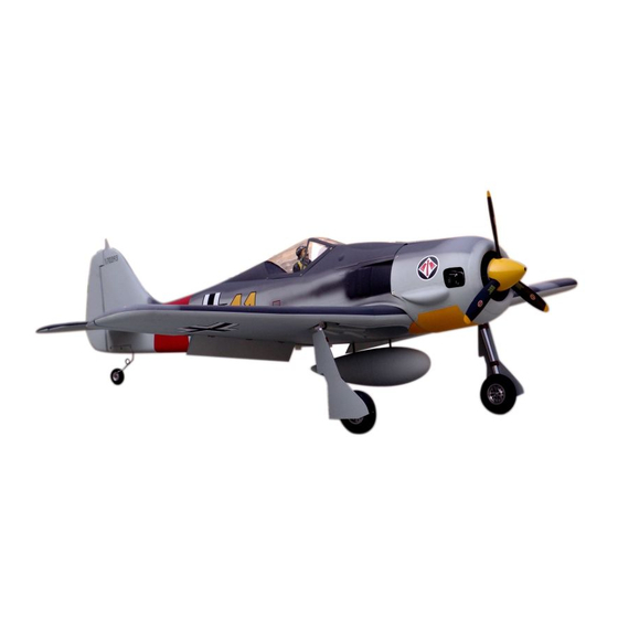
Focke-Wulf Fw 190
Specification:
Length
:1449 mm(57")
Wing Span
:1800 mm(70.9")
Wing Area
:56.1 sq. dm
6.04 sq. ft
Wing Loading :103.4 g/sq. dm
33.7 oz/sq. ft
Flying Weight :5.8 kg(12.8 lbs)
Radio
:6ch&8 servos
Engine
:108 2-cycle
120 4-cycle
SAFETY PRECAUTIONS
INSTRUCTION MANUAL
This R/C airplane is not a toy!
(The people under 18 years old is forbidden from flying this model)
First-time builders should seek advice from people having building
experience.If misused or abused,it can cause serious bodily injury
and damage to property.
Fly only in open areas and preferably at a dedicated R/C flying site.
We suggest having a qualified instructor carefully inspect your
airplane before its first flight.Please carefully read and follow all
instructions included with this airplane,your radio control system
and any other components purchased separately.
Advertisement
Table of Contents

Related Manuals for ESM Focke-Wulf Fw 190


Summary of Contents for ESM Focke-Wulf Fw 190
-
Page 1: Instruction Manual
Focke-Wulf Fw 190 Specification: Length :1449 mm(57") Wing Span :1800 mm(70.9") Wing Area :56.1 sq. dm 6.04 sq. ft Wing Loading :103.4 g/sq. dm 33.7 oz/sq. ft Flying Weight :5.8 kg(12.8 lbs) INSTRUCTION MANUAL Radio :6ch&8 servos Engine :108 2-cycle... - Page 2 (with 9 servos), 6 channel radio for aiplane is highly recommended for this model. : 4-cycle .120 " 3.5 in Spinner Pre-cover the covering with clean cloth! Warning Start at low setting. Increase the setting if Remove the covering with proper necessary.If it is too high,you may damage pressure to cut through only the covering itself.Otherwise, the film.
- Page 3 Assemble the aileron to main wing with instant type CA glue. Be careful Accessory list for the coming installation steps. to ensure the moving parts of the hinges are able to move freely. Clevis Retainer Rod (2x300mm) TP Screw (2.3x12mm) Screw (3x35mm) Servo tray(68.5x56.5x2mm) Wooden...
- Page 4 Secure the servo.Install the nylon control horn Keep some space about 1mm width between and connect the linkage. trailing edge and flap. Two wheel retract system TP Screw (2.3x12mm) Tailing 1.5mm edge Make sure to assemble retracts as instructed below. Rod (2x300mm) Aileron Screw (2x10mm)
- Page 5 Assemble the wheel and gear door to landing gear. Adjustment. Mount the gear door and the wheel to the retract. Install the nylon control horn and connect the linkage. Collar (5mm) Bushing (8X4mm) LockNut(4mm) Retainer Rod (2x300mm) Top view Collar (5mm) TP Screw (3x20mm) ELEVATOR TP Screw (2.6x14mm)
- Page 6 Epoxy the PVC part to the appropriate position in wing Drill holes at appropriate position in the wing According to the rib template drill holes to another carefully as below. for taking the air line and the servo line out. main wing.
- Page 7 Cut away the surplus parts of canopy and PVC parts Accessory list for the coming installation steps. Drill holes to relevant position in the fuselage. carefully along the shade line. Apply instant type CA glue to elevator and pin hinge. Canopy Pin hinge(24x24mm) TP Screw (2.3x8mm)
- Page 8 Be care to notice the distance between the wheel and Drill two holes at the stabilizer root base on rib template Set the U-style wire through the enlarge hole as below. Install the servo of swith. fuselage. and epexy the metal dowel in them. Wood dowel (4x30mm) Add a rubber ring to the clevis for insuring safety...
- Page 9 The sketch map when the tail landing gear be installed The sketch map of the linkage for the rudder Accessory list for the coming installation steps. Assembly of the stabilizer. to the fuselage. and the tail wheel. Make sure to glue securely. If not properly glued, a failure in flight may occur.
- Page 10 Drill holes to the relevant position in the tailing edge Assemble the accelerateor push rod to the engine. The side sketch map of the engine installation finished. Mount the fuel tank to the fuselage. and epoxy the rudder to them. Linkage Stopper Set Screw (3x4mm) 160 mm...
Need help?
Do you have a question about the Focke-Wulf Fw 190 and is the answer not in the manual?
Questions and answers