Advertisement
Quick Links
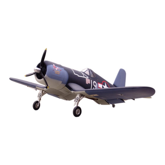
F - 4u Corsair (50cc)
Specification:
Length:
1735mm(68.3")
Wing span:
2160mm(85")
Wing area:
87.00sq.dm(9.39sq.ft)
Wing loading: 135.6g/sq.dm(44.5oz/sq.ft)
Flying weight: 11.8kg(26.0lbs)
Radio:
6ch & 10servos
Engine:
50cc gasoline engine
SAFETY PRECAUTIONS
INSTRUCTION MANUAL
This R/C airplane is not a toy!
(The people under 18 years old is forbidden from flying this model)
First-time builders should seek advice from people having building
experience.If misused or abused,it can cause serious bodily injury
and damage to property.
Fly only in open areas and preferably at a dedicated R/C flying site.
We suggest having a qualified instructor carefully inspect your
airplane before its first flight.Please carefully read and follow all
instructions included with this airplane,your radio control system
and any other components purchased separately.
Advertisement

Subscribe to Our Youtube Channel
Related Manuals for ESM F - 4u Corsair


Summary of Contents for ESM F - 4u Corsair
- Page 1 F - 4u Corsair (50cc) Specification: Length: 1735mm(68.3") Wing span: 2160mm(85") Wing area: 87.00sq.dm(9.39sq.ft) Wing loading: 135.6g/sq.dm(44.5oz/sq.ft) Flying weight: 11.8kg(26.0lbs) INSTRUCTION MANUAL Radio: 6ch & 10servos Engine: 50cc gasoline engine This R/C airplane is not a toy! (The people under 18 years old is forbidden from flying this model) First-time builders should seek advice from people having building experience.If misused or abused,it can cause serious bodily injury...
- Page 2 Gasoline tube Gasoline 6 channel radio for aiplane is highly recommended for this model. 50cc gas engine Optional parts: rubber wheel with metal hub. Spinner nut 22″X8-10 We strongly recommen you use the thread lock for all the screws when you build your model.
- Page 3 Assemble the aileron to main wing with instant type Two wheel retract system Accessory list for the coming installation steps. AB glue. Make sure to assemble retracts as instructed below. Clevis Clevis Collar (3mm) Rod (2x300mm) TP Screw (2.3x12mm) Servo tray(68.5x56.5x2mm) Ball joint Strut Wooden Block(20x20x8mm)
- Page 4 Secure the servo,assemble the servo to the relevant Adjustment. Adjustment. Drill holes in the flap and epoxy the pin hinges in them. position in the outer wing. TP Screw (2.3x12mm) Pin hinge(4.5x67mm) 1.5mm Side View AILERON 30mm Rod (2x300mm) 30mm FLAP Nut (3mm ) Screw (3x10mm)
- Page 5 Assemble the wheel mount to the thick wooden block According to the rib template drill holes and trim a slot in Drag one side of the fiberboard out from the slot in the center wing root until the length of the outer Install the wheel to the fixed landing gear.
- Page 6 According to the illustration,epoxy one side of the Trim the dummy engine cover and the canopy fiberboard in one flap and connect another flap Install the servo of flap to the servo tray. Assemble the cowl to the fuselage with TP screws. carefully along the shaded line.
- Page 7 Install the servo of switch in the fuselage. Install the switch and the throttle servo Epoxy the flaps to the center wing. Assemble the gear doors and the wheels to the retracts. Set screw (3x4mm) LockNut(4mm) Securely glue together. If coming off during flights, you 'll Bushing (8X4mm) lose control of your airplane which leads to accidents! Washer (2mm)
- Page 8 Trim the surplus section from the wheel door and make sure the retract system can retract into the wings Assemble the engine. Drill two holes to relevant position in the fuselage The front view of the engine install completion. accurately when the gear up. Wooden Block (2mm Ply) 120 mm 32mm...
- Page 9 The sketch map of the servo wires pass through the Set the U-style wire through the tail of fuselage as Assemble the stabilizer to fuselage and trim slot to Drill holes to relevant position in the tailing edge of frame in the fuselage. vertical fin and epoxy the rudder to it.
- Page 10 The sketch map of all the steel wires pass the Epoxy the elevator to the stabilizer. Assembly of the stabilizer. Put the frame in the rudder metal wire. former in the fuselage. Make sure to glue securely. Collar (3mm) Rudder servo If not properly glued, a failure in flight may occur.
Need help?
Do you have a question about the F - 4u Corsair and is the answer not in the manual?
Questions and answers