Advertisement
Two wheel retract system
Make sure to assemble retracts as instructed below.
3-way
Strut
pressure inlet
3-way
pressure inlet
Quick release connector
Pressure reduction inlet
Ø1.7mm
Please insure the sealing of the retract
system before flight .
Pleas notice the inner diameter for each
side of the pressure reduction inlet.
Switch
Strut( 90 )
2
Air line (3000mm)
Retainer
3-way pressure inlet
1
Air tank
Clevis
1
Air inlet
Rod (2X300mm)
Quick release connector
1
Pressure reduction inlet
TP Screw(2x14mm)
2
3-way
pressure inlet
Strut
Air inlet
Air tank
Quick release connector
Ø0.2mm
Sw i t ch
1
1
3
1
Air valve
Air valve
1
Pull out length of 8mm
The status when the
2
to make gear down
gear up
1
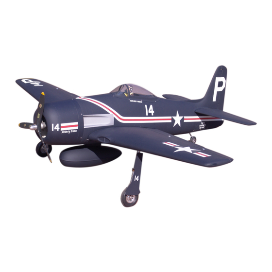
F8F Bearcat
Specification:
Length
:1346 mm(53")
Wing Span
:1860 mm(73.2")
Wing Area
:55.3 sq. dm
5.95 sq. ft
Wing Loading :117.5 g/sq. dm
38.5 oz/sq. ft
Flying Weight :6.5 kg(14.3 lbs)
Radio
:6ch&8 servos
Engine
:108 2-cycle
120 4-cycle
SAFETY PRECAUTIONS
INSTRUCTION MANUAL
This R/C airplane is not a toy!
(The people under 18 years old is forbidden from flying this model)
First-time builders should seek advice from people having building
experience.If misused or abused,it can cause serious bodily injury
and damage to property.
Fly only in open areas and preferably at a dedicated R/C flying site.
We suggest having a qualified instructor carefully inspect your
airplane before its first flight.Please carefully read and follow all
instructions included with this airplane,your radio control system
and any other components purchased separately.
Advertisement
Table of Contents

Related Manuals for ESM F8F Bearcat


Summary of Contents for ESM F8F Bearcat
-
Page 1: Safety Precautions
Two wheel retract system F8F Bearcat Make sure to assemble retracts as instructed below. 3-way pressure inlet 3-way Strut pressure inlet Strut Air inlet 3-way Air tank pressure inlet Quick release connector Quick release connector Pressure reduction inlet Ø0.2mm Sw i t ch Ø1.7mm... - Page 2 Assemble the main wheels as below. Adjustment. Collar (5mm) Collar (5mm) TP Screw (3x20mm) (with 8 servos), Side View TP Screw (2.6x14mm) Washer (3x6mm) RUDDER Wooden Block 20mm 6 channel radio for aiplane is highly recommended for this model. 20mm Wooden supporter Top view Epoxy the wheels to the wings steadily.
- Page 3 Cut away the surplus parts of canopy carefully Epoxy the bottom cover to the fuselage. Assemble the aileron to main wing with instant type CA glue.Be careful Accessory list for the coming installation steps. along the shade line. to ensure the moving parts of the hinges are able to move freely. Clevis Retainer Rod (2x300mm)
-
Page 4: Accessory List For The Coming Installation Steps
Secure the servo.Install the nylon control horn Keep some space about 1mm width between trailing Install the servo of the rudder. Accessory list for the coming installation steps. and connect the linkage. edge and flap. Washer(2x5mm) TP Screw (2.3x12mm) Screw (2x10mm) Canopy Ball joint Tailing... -
Page 5: Tp Screw (2.6X14Mm)
Assemble the accelerator push rod to the engine. Install the nylon control horn and connect the linkage. Mount the fuel tank to the fuselage. Assemble the wheel and the gear door to the retract. Bushing (8X4mm) Linkage Stopper Set Screw (3x4mm) Retainer Washer (2mm) Rod (2x300mm) - Page 6 According to the rib template drill holes in one wing and Drill a hole for assembling the gear cover. The side view of the engine install completion. Epoxy the wheel house to the wings carefully. epoxy wood dowel in them. TP Screw (2.3x8mm) 160 mm Rib template (2mm ply)
-
Page 7: Pin Hinge(24X24Mm)
The standard sketch map when the stabilizer and Epoxy a wooden block at appropriate position in fuselage, Assemble the rudder to the horizontal tail with instant type CA glue.Be Drill holes at relevant position in the fuselage. rudder install completion. and drill a hole in the centre. -
Page 8: Tp Screw (3X20Mm )
Accessory list for the coming installation steps. The sketch map when tail wheel assemble completion. Apply instant type CA glue to elevator and pin hinge. Set the U-style wire through the enlargd hole as below. Retainer Steel wire (0.5x3000mm) Pin hinge(24x24mm) Nose arm(3mm) Clevis Washer (3x6mm)
Need help?
Do you have a question about the F8F Bearcat and is the answer not in the manual?
Questions and answers